Advanced Ladder Logic Programming
See also: Variable Based Advanced Ladder
See also: Screen Development
See also: Product Applications
Topic Menu
Cscape Workspace
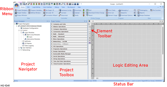
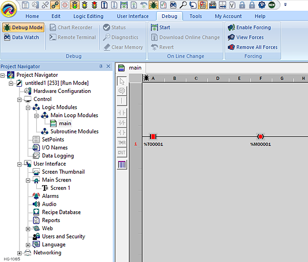
The below dialog shows the workspace windows used when editing an Advanced Ladder program. Individual component windows can be enabled/disabled by selecting them in the in the Home menu.
Note: Users may drop a program in the Logic Editing Area, however the dropping of program is restricted on Screen tab. The Screen tab has its own drop functionality which allows only graphic objects to be dropped.
See also: Shortcut Keys
Navigation Bar in Advanced Ladder
Quick buttons to navigate to various features in Cscape 10.
|
|
Advanced Ladder Cscape Icon |

|
Save File |

|
Hardware Configuration |

|
Connection Wizard |


|
Connect/Disconnect |

|
|

|
Run/Stop |
|
|
Do I/O Mode |


|
Download a Program to a Controller
Upload a Program from a Controller
|


|
|

|
Debugging Functions in Advanced Ladder |

|
|

|
Data Watch |


|
Find and Replace |

|
Project Navigator for Advanced Ladder |

|
Project Toolbox for Advanced Ladder |

|
Not available on Advanced Ladder |

|
Variable Based Advanced Ladder |


|
Cscape Registration and Log In |
Return to the Top: Advanced Ladder Logic Programming
Element Toolbar
Selector Tool 
The Selector is the default mode of the mouse pointer. Program elements may be highlighted for copying or deletion or dragged to a different location in the rung or program. It is possible to click and drag a selection area around multiple elements and rungs by starting in any area that does not contain a programming element. The selection may be copied, deleted, or moved. Returning control to the selector after using other functions or placing elements may be done by clicking the selector tool. Additionally, pressing the ESC key or right-clicking within the program and selecting “Cancel Selection” will accomplish the same thing. By default, control will not return to the selector tool automatically. However, this option may be changed in Cscape Editor Options.
Comment Tool 
The comment tool allows placement of a new comment.
-
Clicking on an empty row will place a new comment in that row.
-
Clicking on the first row of any Ladder Logic rung will insert a comment in that row after moving all logic there and below down one row.
-
It is also possible to right-click in the power rail next to an empty row and select “New Comment”.
Comments are edited by double-clicking within the row where the comment is placed.
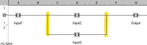
Branch Tool 
The vertical branch tool allows placement of parallel logic within the same rung, aka ‘OR’ logic. The tool acts as a toggle. The mouse icon indicates the placement toggle or eraser toggle accordingly.
-
A vertical branch may be placed if there is not currently one at the mouse location.
-
A vertical branch may be deleted if there is already a branch at the mouse location.
The vertical branches in this example are highlighted.
Normally-Open Contact 
This is a quick way to select and place a Normally-Open Contact. The mouse icon will carry the contact with it while in the logic area to show where it will be placed when the left mouse button is clicked. A contact that has already been placed can be toggled to the opposite type by
right-clicking on the contact and selecting ‘Toggle NC/NO’. Press ESC, click the Selector Tool, or right-click and select ‘Cancel Selection’ to return the mouse to normal.
Normally-Closed Contact 
This is a quick way to select and place a Normally-Closed Contact. The mouse icon will carry the contact with it while in the logic area to show where it will be placed when the left mouse button is clicked. A contact that has already been placed can be toggled to the opposite type by right-clicking on the contact and selecting ‘Toggle NC/NO’. Press ESC, click the Selector Tool, or right-click and select ‘Cancel Selection’ to return the mouse to normal.
Normally-Open Coil 
This is a quick way to select and place a Normally-Open Coil. The mouse icon will carry the contact with it while in the logic area to show where it will be placed when the left mouse button is clicked. A coil that has already been placed can be changed to a different coil type by right-clicking on the coil and selecting ‘Change Coil Type’ to select any other type available. Shortcut keys are also in effect once the placed coil is highlighted with a red square around it, such as Shift-S for Set and Shift-R for Reset, etc. Press ESC, click the Selector Tool, or right-click and select ‘Cancel Selection’ in order to return the mouse to normal.
Timer 
This is a quick way to select and place a Timer function. The mouse icon will carry the function with it while in the logic area to show where it will be placed when the left mouse button is clicked. The same function is used for all the different timers supported in Advanced Ladder Logic. Configuration within the function allows changes to allow for On-Delay, Off-Delay, Retentive, etc. See also: Timer in Advanced Ladder
Counter 
This is a quick way to select and place a Counter function. The mouse icon will carry the function with it while in the logic area to show where it will be placed when the left mouse button is clicked. The same function is used for all the different counters supported in Advanced Ladder Logic. Configuration within the function allows changes to allow for Up-Counter, Down-Counter, etc. See also: Timer in Advanced Ladder
Setpoint Table 
This is the place to access the Setpoint table. See also:Setpoints in Advanced Ladder
The Error List 
The Error List uses the following Syntax:
[BlockType and No.]: [Location – Co-ordinates of the error]: [Description]
-
[BlockType and No.]: Displays the type of block that has reported the error and the no. assigned to it in case of more than one block of same type.
-
[Location – Co-ordinates of the error]: The Row and Column location of the offending element.
-
[Description]: A short description of the problem
Return to the Top: Advanced Ladder Logic Programming
OCS Configuration
See also: Project Navigator for Advanced Ladder
Programming Overview
Steps to a new Cscape Program:
-
Configure Cscape to present the logic editor options required.
-
Start a new Project or a new Program file in the logic editor of choice.
-
Establish a connection to the controller if possible (not required). See Connection Wizard
-
Configure the controller and I/O with the Hardware Configuration. See Hardware Configuration
-
Save the new program.
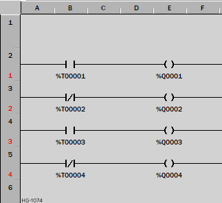
Ladder Logic: Ladder Logic is a programming language developed for use on a controller. It is based on a simulation of older "drum controllers" which provided a set of contacts to be "made" or "broken" as the position of a "rotor" changed. These contacts, when "flattened" into a single line, resemble the rungs of a ladder:
Other Considerations:
-
Configure program and controller security. See Security & Passwords .
-
Name I/O points, variables, etc. See I/O Names or Variable Based Advanced Ladder
-
Write programming for the controller. See Writing the Program in Advanced Ladder
-
Create screens if required. See Screen Development
-
Set up communications. See Networking and Communications
-
Set up datalogging and alarms. See Datalogging or Alarm Configuration (Graphical) for Canvas
New Project in Advanced Ladder
The PROJECT is a centralized location or container for the information about and concerned with an entire installation. When a project is opened, all necessary information is made available.
From Cscape 8.6 onwards, when a new or existing Cscape Project File is opened, a hidden folder will be created for each project inside the Cscape install folder. These folders will be internally named and are temporary hidden folders. The users must not store anything in these folders as they will be removed when the project(s) is (are) closed. To save or copy the programs that are part of project, or the project itself to a different location, use the Project Navigator or main menu. Whenever the user adds an existing copy to a project in project navigator, a copy will be made to the temporary folder allocated to that project. The original file will be untouched. Therefore, if a program is added to one or more projects in project navigator, changes done to the program in each project will modify that project’s local copy only. The original file or copy in other project(s) will not be affected.
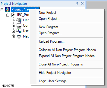
Right-click on Project Navigator or a Project Node to open the following menus:
New Program in Advanced Ladder
Below are the steps to create a new program:
Opening a New Program
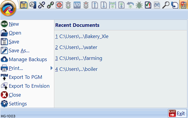
There are several different ways to start a new Cscape program.
-
Option 1: Create a new program through the Cscape Icon. Select New.
-
Option 2: Create a new program through keyboard shortcut - Ctrl+N.
-
Option 3: Create a new program through Project Navigator or a Project Node
Right-Click on Project Navigator or a Project Node to open the following menus:
Select New Program.
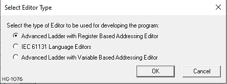
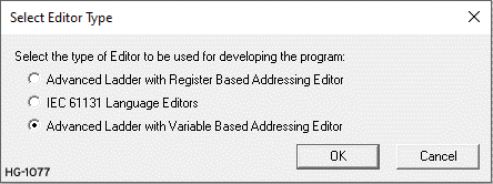
Selecting the Logic Editor Type
By default, newly installed Cscape software starts new programs in the Advanced Ladder with Register-Based Addressing editor and will not give further logic editor options for new programs. However, three different logic editors are available for Cscape programming:
Register-Based Advanced Ladder: The way Cscape started and always has been, register-based programming uses registers such as %R, %T, %M, etc. Each register may optionally be given a name to make references easier to remember, but it is not required. Ladder Logic programming is used, a graphical language based on electrical line diagrams. Advanced Ladder is geared specifically towards the Horner line of products and their features.
Variable-Based Advanced Ladder: Using the same Advanced Ladder editor as the Register-Based editor, variables replace the registers. Variable names are now required while register address references go mostly unused except when linking a variable to hardware such as I/O points or Function Keys.
Connecting to the Controller
This step is optional. The controller type and onboard I/O can be automatically configured if a connection is present. Configuration can also be done manually without the need for a connection if the controller type is known.
Common connections between Cscape and a controller are:
-
USB – Use a USB-A to MiniUSB cable to connect to the controller. Drivers must be installed correctly and fully (2-stage installation doesn’t always automatically take place).
-
Ethernet – Requires proper IP Address assignment on the controller and a connection to the same subnet, or a direct connection to a PC that is properly, manually configured.
-
Serial via MJ port – Using a USB-to-Serial convertor (unless a 9-pin serial port already exists) and the proper programming cable, connect between the PC’s USB port and the controller’s MJ port.
If a controller is available and connected, use the Connection Wizard to establish communications between Cscape and the controller. See Connection Wizard for more details.
Understanding Hardware Configuration
The first thing that should be done with any new Cscape program is to configure which controller and installed I/O is to be used via the Hardware Configuration. This will allow the Cscape software to present the proper options and configurations during the programming process, including I/O point types, features, screen size, etc.
Every Cscape program will have its own Hardware Configuration; the configuration is not automatically carried from one program to the next. Hardware Configuration may be done partially automatically if a connection to the controller is first established (see previous section). Manual configuration is also possible if no controller is available to which to connect. See also: Hardware Configuration
Saving the Program
There are several different ways to save a Cscape program.
-
Option 1: Save a program through the Cscape Icon Select the Cscape icon in the upper left corner, then click Save or Save As.
-
Option 2: Use the keyboard shortcut - Ctrl + S. Pressing Ctrl + S will bring up the dialog below to name the file if this is the first time the file is being saved. Otherwise, it will automatically save the file as the filename that has previously been specified.
-
Option 3: Use the Project Navigator. Right-click on the Untitled Program name and select Save Program As... and name the program.
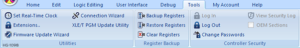
Setting the Security System
If desired or if required by company policy, Security Permissions can be set for both the Cscape file and the controller. From the Main Menu select Tools > Controller Security.
Note: Security measures are optional.
Save the program.
See also: Security & Passwords
See also: Project Navigator for Advanced Ladder
Return to the Top: Advanced Ladder Logic Programming
Writing the Program in Advanced Ladder
Define the I/O Points
Good programming practice insists that the programmer has a defined knowledge of the type and locations of the physical I/O points that must be read or written by the program. Although these can be defined at any time, it is good practice to define them before any code is written.
-
For register-based programming, the I/O points can be given a meaningful name that can be easily remembered.
-
For variable-based programming, register references are mostly not needed. However, the variables meant to be I/O points must be tagged to the corresponding register address of the I/O points. This is because all onboard I/O points are automatically addressed and cannot be changed except in some advanced cases. Knowing the automatic mapping is part of learning the Horner line of controllers.
-
For onboard I/O points, automatic addressing occurs as follows:
-
Digital Inputs start at %I1
-
Digital Outputs start at %Q1
-
Analog Inputs start at %AI1
Note: XL-Series Model 6 I/O, Analog Inputs start at %AI33
-
Analog Outputs start at %AQ1
-
Example 1 - If the 6th Digital Input is wired to a limit switch:
-
For register-based programming, %I6 can be assigned an I/O name such as “DIN_LimitSW”
-
For variable-based programming, a Boolean variable called “DIN_LimitSW” can be tagged to “I6”.
Example 2 - The first Analog Input point could be wired to a 4-20mA pressure transducer:
-
For register based programming, %AI1 can be assigned an I/O name such as “AIN_Pressure1_RAW”
-
For variable-based programming, an INT variable called ‘AIN_Pressure1_RAW’ can be tagged to “AI1”.
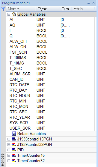
For Variable Based Advanced Ladder only: To open the Program Variables window, enable via Home menu > Program Variables
.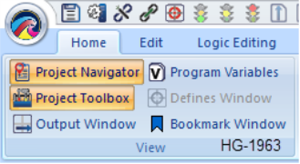
This opens the dockable Program Variables window. For convenience, the variables list includes some pre-defined variables mapped to the corresponding register address of the I/O points, Function keys, System Bits and System Registers. These variables names do not need to be used, the programmer can create and use an alternative variable mapped to any of these I/O points instead.
See Also: I/O Names
See Also: Variable Based Advanced Ladder
Placing Program Elements in Advanced Ladder

|
Cscape Rung Creation |
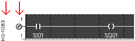
Advanced Ladder requires every rung to be started with an input contact, whether Normally Open or Normally Closed. Placing this contact in Column A will automatically link it to the left-hand power rail with a screw terminal icon, which must be in place for the program to compile. Placing a contact in a column other than Column A will not cause the automatic screw terminal, even if the contact is then dragged into Column A. This can be remedied by right-clicking in the white area to the left of Column A and selecting New Rung, regardless of which column the contact is placed.
Note: In cases where the rung needs to always execute, use a Normally Open contact assigned to “ALW_ON”, which is the %S7 system bit that is always on.
When using the Advanced Ladder editors, use the mouse to select the element to be placed. The mouse cursor is now a tool to place that element. Move the mouse to the position where the element is to be placed, and then click again. The selected element is placed into position. This is referred to as the Snap In.
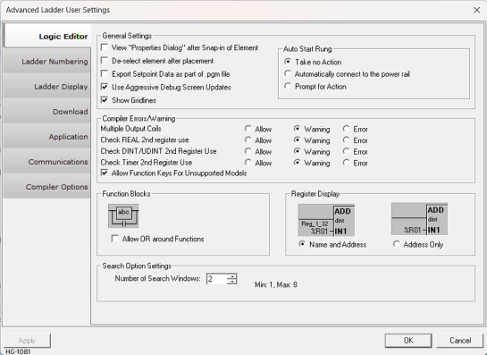
Users can access settings through 2 different paths:
-
Main menu > Left Top Cscape Symbol > User Settings
-
Main menu > Project Navigator > Right Click On Program > Logic User Setting
-
If the De-select element after placement option is checked, the cursor returns to normal and the element's tool becomes deselected. It is necessary to select another (same or different) element before trying to place another.
-
If the De-select element after placement option is unchecked, the cursor retains the element, and the selected element tool remains pressed. Press ‘ESC’, or right-click and select ‘Cancel Selection’, or click the mouse pointer icon in the quick-toolbar to deselect the element
-
If the View Properties dialog after snap-in of element option is checked, the I/O Properties dialog box immediately pops up to allow defining this element.
-
If the View Properties dialog after snap-in of element option is unchecked, nothing further happens. Configuration of the element requires a double-click to open the properties dialog.
Use of these features is a matter of personal preference. Some programmers prefer to enter all elements now, and then go back to edit their properties. Others prefer to completely define each element as it is placed.
Grid Lines
It can be helpful to enable Cscape 's Grid Lines for the Advanced Ladder editors. From the Main Menu select System > Settings > Grid Lines.
Inserting and Deleting Rungs and Lines
Normally, rungs are added one at a time, from the first rung to the last. From a practical standpoint, though, rungs are added on an as-needed basis. This means that rungs are often inserted between two existing rungs.
Moving or Copying Elements
To move existing rungs DOWN, thus opening space for insertion of a new rung, the following methods are available:
-
Right-click on the attachment screw icon associated with the rung to be moved. From the pop-up menu, select Insert 1 blank line. Multiple blank lines can also be inserted by selecting Insert Blank Line. The selected rung and all rungs below it are moved down.
-
Click and drag the attachment screw icon for the rung to be moved and drag it down. The rung and all rungs below it are dragged downwards. Empty space may also be closed by dragging it up. The rung may not be moved up past another rung.
-
To move a function, simply click and drag it. A prompt will appear if the new location will overwrite any other element or if there is any other conflict.
-
To move or copy a section of logic, move the mouse cursor somewhere where there is no logic element, then click and hold the LEFT mouse button while dragging a selection around the section to be moved/copied. Release the mouse button once the selection is complete. The selection can be dragged to another location or copied by right-clicking within the selection and selecting Copy or by pressing Ctrl+C.
-
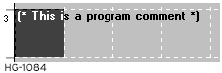
To select a comment, press the left mouse button on the left portion of the comment and drag the mouse until at least the first grid of the comment is selected (as shown below). Additional grids may be selected , but only a single grid on the left needs to be selected to select the entire comment.
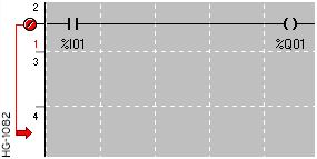
Dragging Rungs
Entire rungs can be moved up or down using drag and drop editing. To start moving a rung, press the left mouse button, on the start of rung screw. Drag the mouse up or down to the desired destination for the rung. Notice the screw of the rung being dragged turns red, and an arrow indicates the position where the rung is to be moved. Releasing the mouse button moves the rung to the new location.
Note: Moving a rung down past other rungs moves the other rungs. This dragging technique keeps the rung order and allows space to be opened to insert new rungs or comments.
Note: One can only move a rung up until it encounters another rung or comment. The arrow indicating the new location stops moving up with this condition exist.
Pasting Elements
To paste a section of logic that has been copied, right-click and select Paste or select Edit > Paste from the Main Menu or press Ctrl+V. The mouse cursor will turn into a crosshair. Click the crosshair where the top-left portion of the copied logic is to be placed. Make sure there is enough space beforehand. An alternate method of copying logic is to select it as noted above, then holding the Ctrl key, then clicking and dragging the selection with the mouse, thus dragging a copy of the selection instead of the selection itself.
To select an entire rung, double-click the left mouse button to the left of the power rail. The entire rung is covered with the darker selecting box as seen below.
-
To delete a rung, right-click on the rung's attachment screw icon, then select Delete Rung from the pop-up menu.
-
To delete multiple rungs, move the mouse cursor somewhere where there is no logic element (Be careful not to select lines that are NOT to be deleted), then click and hold the LEFT mouse button while dragging a selection around the section to be deleted. When the proper material is selected, press the <Delete> key.
-
To delete a single blank line, right-click in the Rule just to the left of the blank line. From the pop-up menu, select Delete Rung.
See also: Project Toolbox for Advanced Ladder
See also: User Settings for Advanced Ladder Overview
Error Check 
There are three (3) possible sources of errors in a Ladder Program:
-
Syntax Errors - Caused by poor entry or misuse of program elements. Example: Creating a rung with only a single Input Contact (-| |- , -|/|-) on the rung.
-
Logical Errors - Caused by asking the controller to do something it can't or using the wrong information. Example: Triggering a timer from %I1 when the user have used %I2.
-
Physical Errors - Caused by misunderstanding or misuse of the hardware, especially the physical I/O points.
The Error Check tool can take care of the syntactical errors. A list of errors is displayed in the Error List dialog. One can go directly to the line causing the error by double-clicking on the error listing line.
Note: The program is automatically checked for syntax errors before downloading.
Bookmark Feature
From Cscape 10.2 onwards, the Bookmark feature has been added in both Register-based and Variable-based Advanced Ladder Logics.
The Bookmark feature allows user to mark specific lines or sections of code for quick navigation and reference.
-
Bookmarks are saved in .csp file
-
Bookmarks can be downloaded to the device and uploaded back.
-
Moving of rungs, renaming of modules and deletion of modules are handled for bookmarks.
-
Moving rungs will update the bookmark line numbers stored
-
Renaming a module will update the stored module names in the bookmark list.
-
Deletion of a module will delete its respective bookmarks.
Add Bookmark
Note: Once bookmarked, a small blue color notch will be displayed in the left grid column.

Note:
-
Bookmarks can only be added for lines with a rung or comment. Empty lines cannot be bookmarked.
-
Subroutine and UDFB modules have start and end rungs so these cannot be bookmarked.
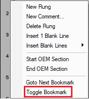
Two Ways to Add a Bookmark.
-
Select a rung/comment line and press CTRL + F2 together to toggle the bookmark.
-
From the left grid column bar, select the Toggle Bookmark option.
Navigating Through Bookmarks
Note: The bookmark navigation is in order of the creation of the bookmarks and only possible for one program at a time.
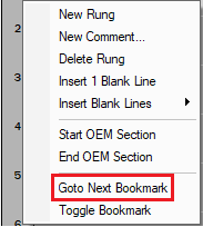
Two Ways to Navigate Through Bookmarks
-
Select a rung/comment line and press CTRL + F2 together to toggle the bookmark.
-
From the left grid column bar, select Goto Next Bookmark
.
The Bookmark Window
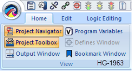
The Bookmark Window option is available in Home menu | View Section of the Ribbon Toolbar.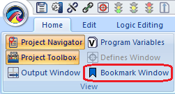
Result: Selecting Bookmark Window displays the Bookmark output window.
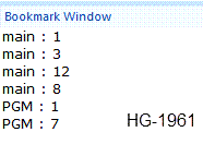
Bookmark Output Window
The Bookmark Output Window displays all of the bookmarks of the opened program or Bookmark Window and can be opened using "ALT + H + B" keyboard shortcuts.
Two Ways to Navigate the Bookmark Output Window
-
Double-clicking on the specific bookmark the user wants to navigate to.
-
Right-clicking a specific bookmark in the Bookmark Window and select Goto Bookmark option.
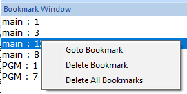
Delete Bookmark: Deletes the selected Bookmark from the program.
Delete All Bookmarks: Deletes all Bookmarks from the program.
Saving the Program
See Saving the Program for more details.
Downloading the Program to the OCS
See Download a Program to a Controller
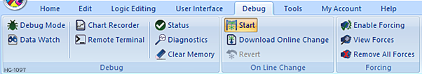
Debugging in Advanced Ladder
See also: Debugging Functions in Advanced Ladder
Debugging helps to find program errors.
Once the program has been successfully cleared of errors, download it to the associated controller. Place the controller in RUN mode, and then start the debugger:
-
From the Main Menu select Debug > Debug Mode/Monitor.
-
Use the right-click option at Debug > Monitor from the Program node in Project Navigator.
While in the debug mode, Cscape maintains a real-time connection to the associated controller. If Pass Through Connections are used, one can debug any controller through the network without being physically connected to the controller.
Return to the Top: Advanced Ladder Logic Programming
Advanced Ladder Menu Options 
Home
View
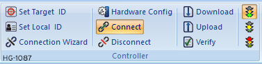
Controller
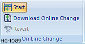
Online Change
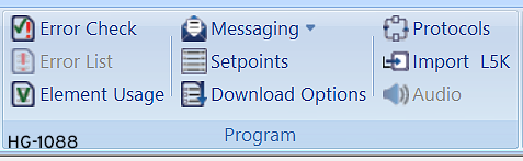
Program
-
Messaging
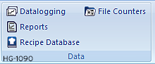
Data
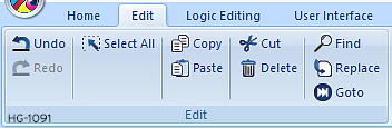
Edit
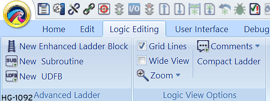
Logic Editing
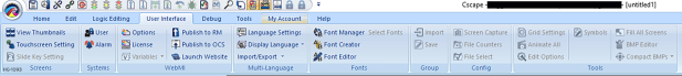
User Interface
Screens
-
Display Settings (Touchscreen Setting)
Systems
WebMI
Multi-Language
Fonts
Config
Tools
-
Grid Settings
-
Animate All Objects -Turns ON/OFF a constant toggle between the different conditions or states of screen objects.
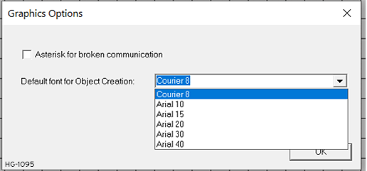
-
Edit Options - Allows for showing asterisks in Comm-linked Data Fields that are not currently active. Allows for a default font to be set for this Cscape program. Selecting Edit Options opens the Graphic Options dialog:
-
Symbols - The Symbol Library is a set of over 2000 graphical symbols used to display the operation and status of automated systems. The symbols are treated as bitmaps or animated bitmaps in the graphics editor.
-
Fill All Screens - Stretches graphics to fill the entire screen on all screens.
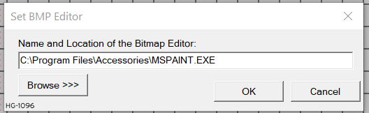
-
BMP Editor - Specify the location of the program used to “Edit Bitmap” from within the Bitmap and Animation objects. When the following dialog opens, select Browse>>> to select file. See also: Animated Picture/Graphic for Canvas or Picture/Graphic Object for Canvas
-
Compact Bitmaps - Allows for Bitmap graphics to be compressed to save graphic memory space. Option allows for just the current screen, all screens, or current project.
Debug
Tools
My Account
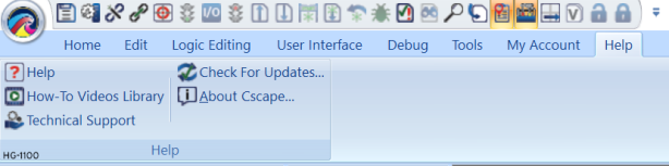
Help
Return to the Top: Advanced Ladder Logic Programming