I/O Names 
See also: Element Usage in Advanced Ladder
Topic Menu
I/O Names Overview
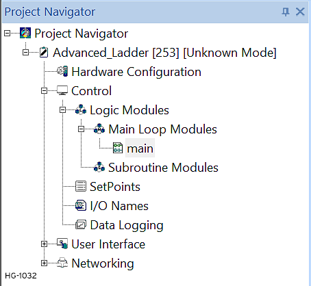
Home > Project Navigator > Control > I/O Names
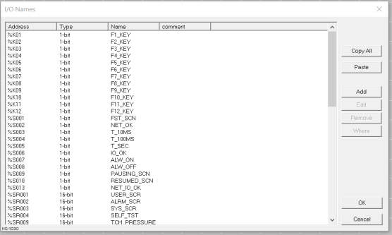
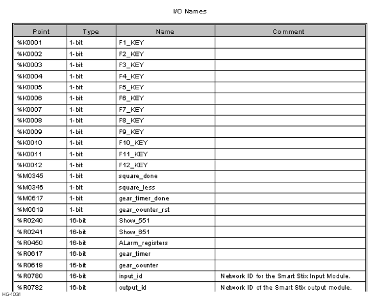
Selecting I/O Names opens the following dialog. This dialog allows one to name individual I/O points for easier reference later. NAMED I/O POINTS can be easier to understand and to recall their purpose, especially if reasonably descriptive names are used.
Add a New Point
Add a new point by clicking the ADD button. This brings up the Point Name Editor.
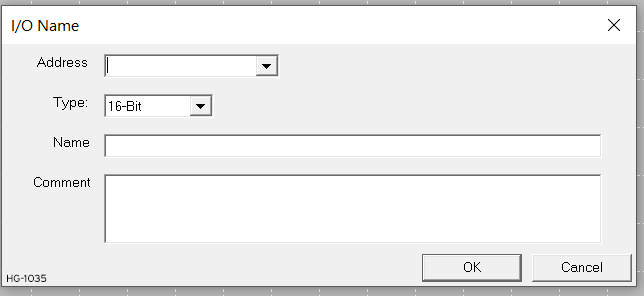
NAME - Enter the desired name for the I/O point in this box. If selecting a point that was already defined, the current name appears in this box. Type over or otherwise edit the name.
Note: There is a 255 character limit for I/O Point Names. Characters must be A-Z, a-z, 0-9, and '_' (underscore). The first letter must be A-Z, a-z, or '_' (underscore).
TYPE - This is a drop-down list that contains all available I/O Point types. Select one from the list.
When selecting a WORD register, supply the BIT OFFSET.
Upon completing the entry, click OK to save the entry and exit or click CANCEL to leave without saving the entry.
Edit an Existing Point
Edit an existing point in one of two ways:
-
Click on the desired point, and then click on the EDIT button.
-
Double-click on the point.
Copying I/O Names
I/O names can be copied to the Windows clipboard to transfer the I/O names within Cscape to an external application. The format used on the clipboard allows the I/O names to be pasted into applications such as Microsoft Word, Excel or other similar programs. The format for the copied data is:
Register <TAB> register size <TAB> name <CRLF>
For example: %R04 16 my_name
Pasting I/O Names
I/O names can be pasted from other Cscape documents or external applications like Microsoft Word or Excel. The I/O name data must be in the format shown in the copy section above.
Note: If the pasted data contains a name for a register that is currently defined in the Cscape I/O names table, the pasted data will overwrite the old name.
Return to the Top: I/O Names
Using I/O Comments 
I/O Comments allow additional text to be assigned to a register.
Editing
When editing I/O names using the Program > IO Names dialog, I/O comments can be entered in the text box labeled "Comment".
Displaying
Currently only contacts and coils display the /IO comments. Moving mouse cursor over a contact or coil and stopping will display a tool tip with the I/O comment text. This text will display for approximately 10 seconds or until the mouse is moved again.
Printing I/O Comments
When I/O names are printed I/O comments are now included in a multi-line format if required.
Return to the Top: I/O Names
The Concept of Named I/O
Cscape supports the concept of NAMED I/O. I/O points can be given alphanumeric NAMES, which become a tag or alias that can be used to locate or define the point elsewhere within Cscape.
To name an I/O point:
-
From the Main menu select Home > Program > I/O Names
-
Double click the IO name sub-node which can be found under control sub-node of the Program node in the Project Navigator
I/O Point Names needs to be as descriptive as possible within the limits of readability. 255 characters per name are allowed. Names such as left_limit_switch or drive_start are much more meaningful than %I15 or %Q03. Use of Named I/O makes remembering the location, type, or function of an I/O point easier to remember and makes ladder source code clearer, cleaner, and easier to understand. For example, I/O points are assigned by a Register Type and a Register Offset (address).
|
Register |
Function |
|
%K0001 |
Start Button |
|
%K0002 |
Stop Button |
|
%I0001 |
Left limit switch |
|
%I0002 |
Right Limit Switch |
|
%I0003 |
Motor is Running |
|
%Q0001 |
Motor Start |
|
%Q0002 |
Forward |
|
%Q0003 |
Reverse |
And the ladder code might look like:
Note: The following code fragment is for example only. This is not actual working code.
| %K0001 %Q0001
|---------] [----------------( )-----
|
| %I0001 %I0003 %Q0002
|---------] [-----] [--------( )----
|
|
| %I0002 %I0003 %Q0003
|---------] [-----] [--------( )----
|
|
But look what happens if Tag Names are assigned to the I/O:
|
Register |
Function |
Tag Name |
|
%K0001 |
Start Button |
USER_START |
|
%K0002 |
Stop Button |
USER_STOP |
|
%I0001 |
Left limit switch |
LEFT_LIMIT |
|
%I0002 |
Right Limit Switch |
RIGHT LIMIT |
|
%I0003 |
Motor is Running |
RUNNING |
|
%Q0001 |
Motor Start |
RUN |
|
%Q0002 |
Forward |
FORWARD |
|
%Q0003 |
Reverse |
REVERSE |
Note: The following code fragment is for example only. This is not actual working code.
| USER_START RUN
|---------] [---------------------( )-----
|
| LEFT_LIMIT RUNNING FORWARD
|---------] [-------] [-----------( )----
|
| LEFT_LIMIT RUNNING REVERSE
|---------] [-------] [-----------( )----
|
|
The Ladder source code is now almost in English. At the least, the function of each point is clearly defined without having to refer back to the list of assigned I/O points. This makes the code easier to decipher, especially to someone who might be unfamiliar with the code but still needs to come up to speed quickly.
Long I/O Names
See also: Using I/O Comments
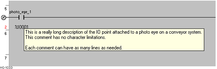
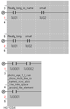
Long I/O names assigned to contacts or coils can extend into the next cell if it is empty. Notice the example below where %I01 has a long name that is fully displayed only if the cell next to the contact is empty.
Return to the Top: I/O Names
Define an I/O Point
See also: Element Usage in Advanced Ladder
The Most common is to first select an element from the Element Toolbar, Sticky Toolbar or Project Toolbox and place the element into the program, and then define the element in the Define Properties dialog. I/O points are either contacts (-| |- , -|/|-) or coils (-( )- ) . I/O Points can be either external (%I![]() Single-bit input registers. Typically, an external switch is connected to the registers., %Q, etc) or internal (%K, %T
Single-bit input registers. Typically, an external switch is connected to the registers., %Q, etc) or internal (%K, %T![]() Non-retentive single-bit registers., etc). I/O points are differentiated from each other by their TYPE and OFFSET: %K01, %QG05, etc. See also: Contacts and Coils in Advanced Ladder
Non-retentive single-bit registers., etc). I/O points are differentiated from each other by their TYPE and OFFSET: %K01, %QG05, etc. See also: Contacts and Coils in Advanced Ladder
To define an I/O point, specify the TYPE and OFFSET. The user can optionally specify a NAME to be used to access the point at other locations in the program. There are several ways to define (or redefine) an I/O point. The most common is to first select an element from the Element Toolbar, place the element into the Ladder Program, and then define the element in the Define Properties dialog.
Note: The Define Properties dialog can be opened by:
-
Double-clicking on the element
-
Right-clicking on the element automatically when the element is placed .
Use this dialog to define the I/O point:
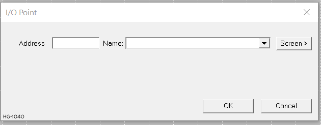
Required Properties
I/O Address - From the drop-down list, choose the desired controller register types for the I/O Point. At the right end of the Type, add the ADDRESS (also called OFFSET). Addresses range from '1' (one) to some maximum number as defined by the target controller.
Bits can be accessed from within WORD registers (%R, %AI![]() 16-bit input registers used to gather analog input data such as voltages, temperatures, and speed settings coming from an attached device., etc). For example, to access the fourth bit of Register R5, enter the Address as %R5.4.
16-bit input registers used to gather analog input data such as voltages, temperatures, and speed settings coming from an attached device., etc). For example, to access the fourth bit of Register R5, enter the Address as %R5.4.

All Addressing is "1 based"; that is, all address start with '1' (not zero '0')
Optional Properties
Name - This is a tag or alias assigned to this point. Names are used to make the use and location of I/O points easier (See:The Concept of Named I/O ).
Input or Output? - It is possible to assign an INPUT CONTACT (-| |- , -|/|-) to reference an OUTPUT COIL:
This could be used in this example:
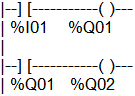
In Rung 1, %Q01 is the Output Coil responding to Input Contact %I01. In Rung 2, %Q01 references an Input Contact.
Display Screens
A coil (-( )- ) can be define as a Display (%D![]() Single-bit flags used to control or monitor display screen on units that have screens.) point. If this is the case, an additional button is placed on the Define I/O Point dialog. This button allows one to go directly to the Screen Editor to edit or modify the display produced by this point.
Single-bit flags used to control or monitor display screen on units that have screens.) point. If this is the case, an additional button is placed on the Define I/O Point dialog. This button allows one to go directly to the Screen Editor to edit or modify the display produced by this point.
Return to the Top: I/O Names
I/O Point and Memory Reference Addressing
See also: Element Usage in Advanced Ladder
Cscape uses the conventional method of addressing used by other controllers:
%[type][offset]
Where: % is a required character
[type] is a register type - R, I, Q, AQ, etc.
[offset] is the "address" of the register, 1, 5, 243, etc.
Resulting in memory references such as %R15, %AI02, %I01, etc.
Cscape also accepts the addressing format commonly used as a short cut in GE/Fanuc products.
[offset][type]
[offset] is the "address" of the register, 1, 5, 243, etc.
[type] is a register type - R, I, Q, AQ, etc.
For example 1I can be used to enter the address %I1.
When creating or using memory references, it is permissible in Cscape to leave off the % prefix unless otherwise noted. Memory references can be entered as R15, AI02, I1, etc. Cscape automatically inserts the %.
Usage of ".U" in registers
By entering %R1.U in the ladder blocks, cscape will consider the upper/higher byte value of the register. The following ladder blocks supports ".U" functionality:
-
Move Data
-
String Move
-
String Compare
-
String Length.
Bit-Mapped Addressing of 16-bit Registers
Cscape also allows individual bits within 16-bit registers to be accessed directly. For example, to access Bit 4 in Register %R5 --
-- Type in the address %R5.4 . Bit offset values range from 1 to 16.
If one attempts to associate a 16-bit register (R, AI, AQ, etc) with a bit-wise element, they are forced to use Bit Addressing to properly specify which bit of the word is to be used with the action.
When using a WORD register in functions such as Math Functions, the bit addressing is not required, and register offset may be specified as %R5.
Some functions that normally work on WORD data can be configured to work with "bit fields" in discrete memory (%I![]() Single-bit input registers. Typically, an external switch is connected to the registers., %Q
Single-bit input registers. Typically, an external switch is connected to the registers., %Q![]() Single-bit output registers. Typically, these bits are connected to an actuator, indicator light or other physical outputs., etc) by using bit addressing. In this case, however, the Bit Offset must lie on word boundaries, "1", "17", "33", etc.
Single-bit output registers. Typically, these bits are connected to an actuator, indicator light or other physical outputs., etc) by using bit addressing. In this case, however, the Bit Offset must lie on word boundaries, "1", "17", "33", etc.
Bit-Mapped Addressing of 32-bit Registers
Bit-mapped addressing of 32-bit registers is not allowed. Bit offset values range from 1 to 16.
In order to access all 32 bits in a double register it is necessary to address the upper word of the register separately. Storage is such that the lower word is stored in the first (base) register, and the upper word is stored in the next consecutive register.
For example. if the 32-bit binary 0000000000000001 0000000000000100 value (65540 decimal) is loaded into register %R43, %R43 contains 0000000000000100 and %R44 contains 0000000000000001. Therefore, to check Bit 17 of the DWORD![]() DWORD - [Data Type DWORD] - A string of 32 consecutive bits. DWORD values are used where the value of the data is not as important as the bit patterns (shifts and rotates). stored at %R43, one must check Bit 1 of %R44, addressed as %R44.1.
DWORD - [Data Type DWORD] - A string of 32 consecutive bits. DWORD values are used where the value of the data is not as important as the bit patterns (shifts and rotates). stored at %R43, one must check Bit 1 of %R44, addressed as %R44.1.
Numbering Base
In Cscape Advanced Ladder Logic, all offsets begin with 1 (one). 0 (zero) is not valid for register offset nor bit offset addressing.
Register offsets are thus in the range of 1 to X, where X is the maximum number of register in a particular model of controller. For example, if the selected controller has 2048 %R registers, they are addressed as %R01 through %R2048.
Bit Offsets are in the range of 1 to 16. Groups of Boolean![]() Boolean- [Data Type BOOL] - A single bit, binary value, or register/variable. Boolean points have only two possible values, 'TRUE' or 'FALSE'. registers can be accessed as a 16-bit register. In this case, though, the Bit offset must lie on a 16-bit boundary, 1, 17, 33, etc.
Boolean- [Data Type BOOL] - A single bit, binary value, or register/variable. Boolean points have only two possible values, 'TRUE' or 'FALSE'. registers can be accessed as a 16-bit register. In this case, though, the Bit offset must lie on a 16-bit boundary, 1, 17, 33, etc.
See Also: Controller Specifications
Edit Boxes
When configuring program elements, the Register Type and Offset are most often entered in an Edit Box. In this case the percent sign % is not needed. When configuring a program element, %R15 and R15 both refer to the same location.
When entering a Register Type and Offset into string values such as with the Math Equations element, the percent sign % must be used to differentiate a memory reference address from a named item.
Predefined I/O Points
See Also: System Register Tables
Certain I/O Points (memory references) have been predefined. These points are immediately available for use in the programs.
|
Point |
Name |
Function |
|
%S01 |
FST_SCN |
Indicates First Scan after Power-up or Stop-to-Run |
|
%S02 |
NET_OK |
Network is OK |
|
%S03 |
T_10MS |
10m pulse (ON for 5ms OFF for 5ms, repeat) |
|
%S04 |
T_100MS |
100ms pulse (ON for 50ms, OFF for 50 ms, repeat) |
|
%S05 |
T_1SEC |
1 second pulse (ON for 500ms, OFF for 50ms, repeat) |
|
%S06 |
IO_OK |
I/O is OK |
|
%S07 |
ALW_ON |
Always ON |
|
%S08 |
ALW_OFF |
Always OFF |
|
%S09 |
PAUSING_SCN |
Pause 'n Load soon |
|
%S10 |
RESUMED_SCN |
Pause 'n load done |
|
%S11 |
FORCE |
I/O being forced* |
|
%S12 |
FORCE_EN |
Forcing is enabled* |
|
%S13 |
NET_IO_OK |
Network I/O is OK |
|
%K01 |
F1_Key |
Function Key 1 image |
|
%K02 |
F2_Key |
Function Key 2 image |
|
%K03 |
F3_Key |
Function Key 3 image |
|
%K04 |
F4_Key |
Function Key 4 image |
|
%K05 |
F5_Key |
Function Key 5 image |
|
. |
||
|
. |
||
|
%K0x |
Fx_Key |
Function Key X image |
*See Forcing for more details.
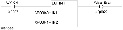
EXAMPLE #1 - Horner Advanced Ladder Logic requires every rung to start with a contact and it is not possible to simply start a rung with a function block that always needs to execute. The pre-defined ALW_ON system bit, aka %S7, may be used with a Normally Open contact for this purpose:
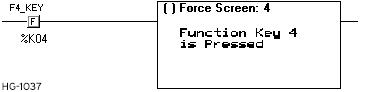
EXAMPLE #2 - The Function Keys are used to provide user-selected input to a program. For example, the following code displays a screen whenever Function Key 4 is pressed:
Return to the Top: I/O Names
Controller Register Types
See also: Controller Specifications
Note: For Register-Based Advanced Ladder Logic
Controllers offer a wide variety of Register Types for programming. In most cases, the controller treats register types as if they were memory locations. This is especially convenient for physical I/O, as they appear as just another register. Programming is simplified, as special instructions are not needed to differentiate between external I/O devices and internal memory storage locations.
The following is a list of register types available in the Horner APG OCS line. Note that all register types are not available in all OCS's, and all OCS's do not have the same number of registers of any specific type. Refer to the information that comes with the OCS for a complete list of registers available.
-
%AI Analog Input - 16-bit input registers used to gather analog input data such as voltages, temperatures, and speed settings coming from an attached device.
-
%AQ Analog Output - 16-bit output registers used to send analog information such a voltages, levels or speed settings to an attached device.
-
%AIG Global Analog Input - Specially defined 16-bit input registers that come from the network.
-
%AQG Global Analog Output - Specially defined 16-bit output registers that go to the network.
-
%D Display Bit - These are digital flags used to monitor or control the displaying of screens on a unit with a screen. Assigning a %D bit to an input contact allows monitoring for that screen to be active. Assigning a %D bit to an output coil allows switching to or forcing the corresponding screen number.
-
%I Digital Input - Single-bit input registers. Typically, an external switch is connected to the registers.
-
%IG Global Digital Input - Specially defined single-bit inputs that come from the network.
-
%K Key Bit - Single-bit flags used to give the programmer direct access to any front panel F-keys appearing on a unit.
-
%M Retentive Bit - Retentive
 Registers or variables are retentive if their data remains unchanged after a RUN/STOP sequence, or after a Power Down / Power Up sequence. single-bit
registers.
Registers or variables are retentive if their data remains unchanged after a RUN/STOP sequence, or after a Power Down / Power Up sequence. single-bit
registers. -
%Q Digital Output - Single-bit output registers. Typically, these bits are connected to an actuator
A device used to move or control a mechanism. Its purpose is to translate a control signal into a mechanical action. An example would be an electric motor., indicator light -
%QG Global Digital Output - Specially defined single-bit outputs that go to the network.
-
%S System Bit - Single-bit bit coils predefined for system use.
-
%SRSystem Register Tables - 16-bit registers predefined for system use.
Return to the Top: I/O Names