Forcing

See also: Debugging Functions in Advanced Ladder
See also: Debugging Functions in IEC
Topic Menu
Warning: Forcing I/O allows physical inputs to be overridden or physical outputs to be activated. Without full knowledge of your system this can cause personal injury or equipment damage.
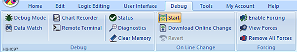
Enable Forcing 
Forcing must be enabled on the controller before forcing registers. Select the Debug menu, then go to the Forcing sub menu and select Enable Forcing.
Debug > Forcing > Enable Forcing
If items are being forced and Enable Forcing is turned OFF, the controller will no longer force the I/O but will retain the list of forced items. Re-enabling the forcing will resume forcing using the last set of forcing states. The forcing state (enabled or disabled) and forcing table are stored in battery backed memory on the controller and will be retained through a power cycle.
Remove Forcing 
Selecting the Remove All Forces from the Forcing menu will not disable forcing but will clear the list of registers being forced.
Debug > Forcing > Remove all Forces
To Disable Forcing, click on the enable forcing option again.
Debug > Forcing > Enable Forcing
Forcing a Contact or Coil
Once Forcing is enabled start debugging the ladder program that contains the registers to force. Currently only the %I![]() Single-bit input registers. Typically, an external switch is connected to the registers. and %Q registers can be forced.
Single-bit input registers. Typically, an external switch is connected to the registers. and %Q registers can be forced.
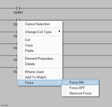
Right-click on the contact or coil that is to be forced and select the Force sub menu. Now select Force ON to force the register ON (1), Force OFF to force the register OFF (0), or Remove Force to stop forcing the register and allow normal ladder control of the register.
Note: Forcing is intended to simulate physical or network inputs and to stimulate physical or network outputs for testing purposes. When an output is forced ladder logic is still allowed to write and change the forced register. Once the ladder scan is complete the register is updated with its forced value, and the physical output is updated. For example, if %Q1 is forced ON, yet a coil turns %Q1 OFF, any contacts after the coil will act as if %Q1 is OFF. When the scan is complete %Q1 will be forced ON before the physical outputs are updated.
The following is a list of events completed during the scan loop:
- Read the physical and network inputs
- Override any forced inputs
- Execute the ladder logic
- Override any forced outputs
- Write the physical and network outputs
- Go back to item 1
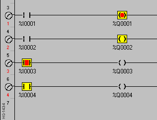
Display of Forced Registers
When a register is forced and the program is being debugged, the forced state is indicated by a black box filled with yellow around the contact or coil. Contacts or coils that are forced ON are filled with RED, while contacts or coils that are forced OFF are not filled.
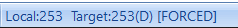
Indicators of Forcing
When one or more registers are being forced and forcing is enabled, the status bar will show [FORCED] after the target status. When forcing is not enabled OR no items are being forced, the status bar will show [no forces]. See also: Cscape Status Bar
-
When forcing is enabled %S12 will become active. When forcing is enabled and one or more registers are being forced %S11 will become active.
-
When %S11 is active the controller will flash the OK LED to indicate one or more registers are being overridden.
Viewing a List of Forced Items 
To view a list of the registers being forced select the Debug menu, then select the Forcing menu and then choose View Forces. This will display the dialog shown below.
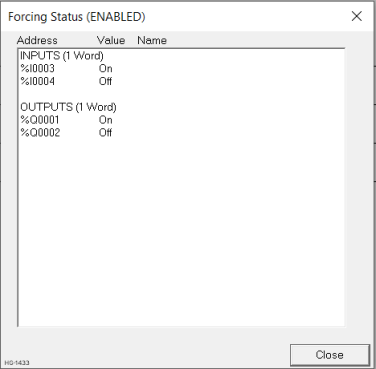
The title bar of this dialog will show (ENABLED) or (DISABLED) to indicate if forcing is enabled or disabled on the target controller. The forcing table is divided into two sections INPUTS and OUTPUTS. INPUTS indicate contacts that were forced while OUTPUTS indicate coils that are being forced. Under each of these sections is a list of registers and the current force state (ON or OFF) of the register.
Because forcing information is stored in battery backed RAM there is a limit to the number of contacts and coils that can be forced. After the title INPUTS or OUTPUTS there is a number of WORDS used in the forcing table, "(1 Word)". Every 16 consecutive register bits require 1 WORD![]() Word - [Data Type WORD] - A string of 16 consecutive bits. WORD values are used where the value of the data is not as important as the bit patterns (shifts and rotates). of forcing space. At the time of printing the controller limit was set to 42 WORDs of forcing allowing a combination of up to 672 contacts and coils to be forced. If the registers forced are not sequential this number can be lower. Cscape keeps track of this resource and will generate an error message if the forcing table becomes full.
Word - [Data Type WORD] - A string of 16 consecutive bits. WORD values are used where the value of the data is not as important as the bit patterns (shifts and rotates). of forcing space. At the time of printing the controller limit was set to 42 WORDs of forcing allowing a combination of up to 672 contacts and coils to be forced. If the registers forced are not sequential this number can be lower. Cscape keeps track of this resource and will generate an error message if the forcing table becomes full.
Return to the Top: Forcing