Contacts and Coils in Advanced Ladder
See also: Project Toolbox for Advanced Ladder
Topic Menu
Home > View > Project Toolbox > Contacts and Coils
The Contacts and Coils operations are the simplest Ladder Logic functions and consists of Contacts and Coils. These represent the parts of a relay, hence the full name “Relay Ladder Logic”, or RLL. A relay is one or more sets of electrical contacts that are either closed or opened when power is applied to an electromagnetic coil. The “Normal” state is considered the “Not Powered” state of the relay. All Contacts and Coils operations only have two states which are TRUE (1) or FALSE (0). Every Contacts and Coils operation is available via the Quick Toolbar. Both Contact types and the Normally Open Coil have a dedicated button on the Quick either directly with a button or indirectly by placing a similar function and then changing it as described in the following sections.
Contacts in Advanced Ladder
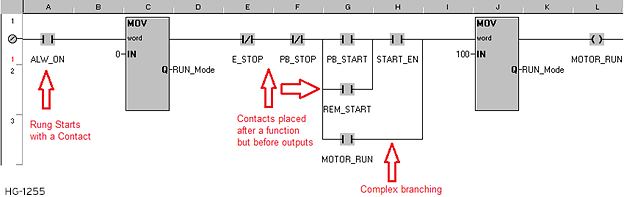
All Ladder Logic rungs in Horner Advanced Ladder Logic must start with a contact. It is not allowed to connect a function other than a contact to the left-hand power rail to start a rung. While Cscape will allow placement and connection in such a manner, a fault will occur upon error check or download and the program will not be allowed to download.
The Error Check tool can take care of the syntactical errors. A list of errors is displayed in the Error List dialog. One can go directly to the line causing the error by double-clicking on the error listing line.
Note: The program is automatically checked for syntax errors before downloading.
Note: There are three (3) possible sources of errors in a Ladder Program:
-
Syntax Errors - Caused by poor entry or misuse of program elements. Example: Creating a rung with only a single Input Contact (-| |- , -|/|-) on the rung.
-
Logical Errors - Caused by asking the controller to do something it can't or using the wrong information. Example: Triggering a timer from %I1 when the user have used %I2.
-
Physical Errors - Caused by misunderstanding or misuse of the hardware, especially the physical I/O points.
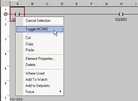
Contacts may be placed in series (AND Logic) and/or in parallel (OR Logic), by using vertical branches, to create complex paths for power flow. A rung may not end with a contact. It is possible in some cases for contacts to be placed after other functions but before coil outputs. It is possible to change the type of a contact that has already been placed. Select the contact (click so that a red square appears around the contact position), then right-click the contact and select “Toggle NC/NO”. This saves the steps of deleting a contact, then placing and addressing a new one.
Normally Open Contact 
The Normally Open Contact acts as an input condition that, when the associated variable/register is FALSE, is Open. The variable/register may be linked directly to a digital input or may be acted upon with a coil addressed to the same variable/register elsewhere in the program logic. When that variable/register becomes TRUE, the contact closes and power flow through the contact is allowed. In Debug mode, the CLOSED state will display within the contact symbol as a red highlight.
A shortcut for selecting a Normally Open contact to place is the F2 key. The Normally Open Contact is also available as a button on the Quick Toolbar. Right-click on a contact that has already been placed to toggle it between Normally Closed and Normally Open types.
In Register Based Advanced Ladder Logic:

In Variable Based Advanced Ladder Logic:

Normally Closed Contact 
The Normally Closed Contact acts as an input condition that, when the associated variable/register is FALSE, is Closed. The variable/register may be linked directly to a digital input or may be acted upon with a coil addressed to the same variable/register elsewhere in the program logic. When that variable/register becomes TRUE, the contact opens and power flow through the contact is no longer allowed. In Debug mode, the CLOSED state will display within the contact symbol as a red highlight.
A shortcut for selecting a Normally Closed contact to place is the F3 key. The Normally Closed Contact is also available as a button on the Quick Toolbar. Right-click on a contact that has already been placed to toggle it between Normally Closed and Normally Open types.
In Register Based Advanced Ladder Logic:

In Variable Based Advanced Ladder Logic:

Contacts Example
Return to the Top: Contacts and Coils in Advanced Ladder
Coils in Advanced Ladder
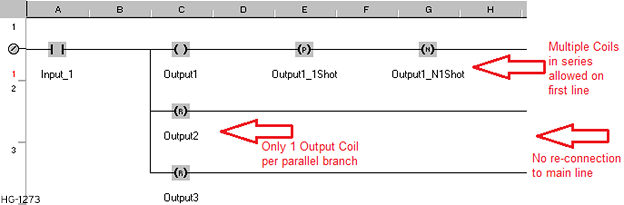
Coils act as a BOOLEAN![]() Boolean- [Data Type BOOL] - A single bit, binary value, or register/variable. Boolean points have only two possible values, 'TRUE' or 'FALSE'. output/result of a rung of Ladder Logic. A rung may not be started with a coil. If a coil is used, it is almost always required to be the last thing on the rung along with other coils. Coils are not necessary to complete a rung of Ladder Logic if some other function with a result (more than just power flow) is in place. Those functions are usually, but not always, indicated with a parameter shown on the right side of the function block. Multiple output coils may be used on a single rung. Though Ladder Logic is based on electrical diagrams, Cscape allows output coils placed in series to power multiple outputs. Multiple outputs may also be placed in parallel, which is how it would correctly be done electrically but this will take more visual space in the program.
Boolean- [Data Type BOOL] - A single bit, binary value, or register/variable. Boolean points have only two possible values, 'TRUE' or 'FALSE'. output/result of a rung of Ladder Logic. A rung may not be started with a coil. If a coil is used, it is almost always required to be the last thing on the rung along with other coils. Coils are not necessary to complete a rung of Ladder Logic if some other function with a result (more than just power flow) is in place. Those functions are usually, but not always, indicated with a parameter shown on the right side of the function block. Multiple output coils may be used on a single rung. Though Ladder Logic is based on electrical diagrams, Cscape allows output coils placed in series to power multiple outputs. Multiple outputs may also be placed in parallel, which is how it would correctly be done electrically but this will take more visual space in the program.
Note: Multiple outputs in series on anything other than the main line are not allowed and will cause an error.
Note: When using multiple output coils in parallel using the vertical Branch Tool, only create a branch to the left of the outputs. Do not reconnect the branch to the main line on the right side of the outputs.
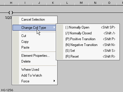
It is possible to change the type of a coil that has already been placed. Select the coil (click so that a red square appears around the coil position), then right-click the coil, select “Change Coil Type”, and select one of the available types. This saves the steps of deleting a coil, then placing and addressing a new one of the correct type and is especially useful since the Quick Toolbar only has one type of coil.
Normally Open Coil 
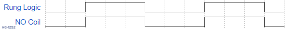
For Normally Open Coils, if all input conditions are TRUE, no functions have faulted out, and power flow has reached the coil at the end of the rung, it becomes TRUE. Should any condition or function no longer allow power flow to reach the output, the coil will actively become FALSE. The coil variable/register may be addressed directly to a digital output or to some intermediate, internal variable for use elsewhere in program logic. In Debug mode, the TRUE state will display within the contact symbol as a red highlight. A shortcut for selecting a Normally Open coil to place is the F9 key.
The Normally Open Coil is also available as a button on the Quick Toolbar. To change any coil that has already been placed in logic, select and right-click to change the coil type. Select any coil that has already been placed and press Shift-<spacebar> to change it to Normally Open. Multiple Normally Open coils addressed to the same variable/register may cause unwanted operation due to how the scan of the OCS works. If multiple coils are used in this way, the state of the coil used latest in the program logic will win out over all others during the output phase of the scan.
In Register Based Advanced Ladder Logic:

In Variable Based Advanced Ladder Logic:

Normally Closed Coil 
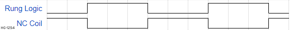
For Normally Closed Coils, if all input conditions are TRUE, no functions have faulted out, and power flow has reached the coil at the end of the rung, it becomes FALSE. Should any condition or function no longer allow power flow to reach the output, the coil will actively become TRUE. This is the opposite of a Normally Open Coil.
Note: It is not necessarily common practice to use Normally Closed Coils. The same operations can usually be accomplished in other, more intuitive fashions.
The coil variable/register may be addressed directly to a digital output or to some intermediate, internal variable for use elsewhere in program logic. In Debug mode, the TRUE state will display within the contact symbol as a red highlight. To change any coil that has already been placed in logic, select and right-click to change the coil type. Select any coil that has already been placed and press Shift-/ to change it to Normally Closed. Multiple Normally Closed coils addressed to the same variable/register may cause unwanted operation due to how the scan of the OCS works. If multiple coils are used in this way, the state of the coil used latest in the program logic will win out over all others during the output phase of the scan.
In Register Based Advanced Ladder Logic:

In Variable Based Advanced Ladder Logic:

Positive Transition Coil 
For Positive Transition Coils, aka (Rising-Edge) One-Shots or P-Coils, if all input conditions are TRUE, no functions have faulted out, and power flow has reached the coil at the end of the rung, it becomes TRUE for only a single scan of the OCS. Once the scan returns to this location in the program logic, the output will become FALSE, regardless of the state of the rung leading up to the coil. Some portion of the rung leading up to the Positive Transition Coil must make the power flow to the coil FALSE, then the rung become TRUE again for the Positive Transition Coil to once again become TRUE for one scan only. The Positive Transition Coil should always be addressed to some intermediate, internal variable for use elsewhere in program logic. Addressing it to a physical output would only result in the output being active for a couple of milliseconds, if at all. In Debug mode, the TRUE state will likely never display due to the single scan the output is on and the much slower nature of Debug mode.
A shortcut for placing a Positive Transition coil is to press F9 to select a coil, click to place it in the program, then press Shift-P to change the coil type to Positive Transition. To change any coil that has already been placed in logic, select and right-click to change the coil type or use the Shift-P shortcut on a selected coil.
Multiple Positive Transition Coils addressed to the same variable/register should not be used. Positive Transition Coils should not be placed in Subroutines or any other logic that would not be scanned on every scan of the OCS.
In Register Advanced Ladder Logic:
![]()
In Variable Based Advanced Ladder Logic:
![]()
![]()
Negative Transition Coil 
For Negative Transition Coils, aka (Falling-Edge) One-Shots or N-Coils, all input conditions must become TRUE in order for power flow to reach the output. However, the output will not become active until those conditions are again FALSE, at which point the Negative Transition Coil will become TRUE for only a single scan of the OCS. Once the scan returns to this location in the program logic, the output will become FALSE. The logic in the rung leading up to the coil must become TRUE again, then FALSE again for the Negative Transition Coil to once again become TRUE for one scan only. The Negative Transition Coil should always be addressed to some intermediate, internal variable for use elsewhere in program logic. Addressing it to a physical output would only result in the output being active for a couple of milliseconds, if at all. In Debug mode, the TRUE state will likely never display due to the single scan the output is on and the much slower nature of Debug mode.
A shortcut for placing a Negative Transition coil is to press F9 to select a coil, click to place it in the program, then press Shift-N to change the coil type to Negative Transition. To change any coil that has already been placed in logic, select and right-click to change the coil type or use the Shift-N shortcut on a selected coil.
Multiple Negative Transition Coils addressed to the same variable/register should not be used. Positive Transition Coils should not be placed in Subroutines or any other logic that would not be scanned on every scan of the OCS.
In Register Based Advanced Ladder Logic:
![]()
In Variable Based Advanced Ladder Logic
![]()
![]()
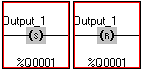
Set and Reset Coil 

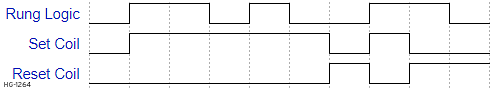
For Set Coils, aka Latches, all input conditions must become TRUE for power flow to reach the output, at which point the output becomes TRUE. The output will stay TRUE, regardless of the state of the logic in front of it. A Reset Coil, addressed to the same variable/register as the Set Coil, must be activated elsewhere in program logic for the output to become FALSE. Set and Reset Coils are addressed directly to an output or to some intermediate, internal variable for use elsewhere in program logic. In Debug mode, a Set Coil will be highlighted red if the associated variable/register is TRUE (Set), while a Reset Coil will be highlighted red if the associated variable/register is FALSE (Reset).
A shortcut for placing a Set Coil is to press F9 to select a coil, click to place it in the program, then press Shift-S to change the coil type to Set. Shift-R would change the type to Reset. To change any coil that has already been placed in logic, select and right-click to change the coil type or use the Shift-S or Shift-R shortcuts on a selected coil.
Multiple Set and Reset Coils addressed to the same variable/register may be used. When using Set and Reset coils… whether one of each, or multiples of one, or multiples of each… the last one scanned as part of the program wins out during the output phase of the scan. Between one instance and the next in program logic, the variable/address will carry the state of one coil until it is overwritten by another.
In Register Based Advanced Ladder Logic:
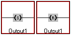
In Variable Based Advanced Ladder Logic:
Coils Example
Return to the Top: Contacts and Coils in Advanced Ladder