Timer in Advanced Ladder 
See also: Counters in Advanced Ladder
See also: Project Toolbox for Advanced Ladder
Topic Menu

|
Timer & Counter Setup |
Home > View > Project Toolbox > Timer/Counter Operations
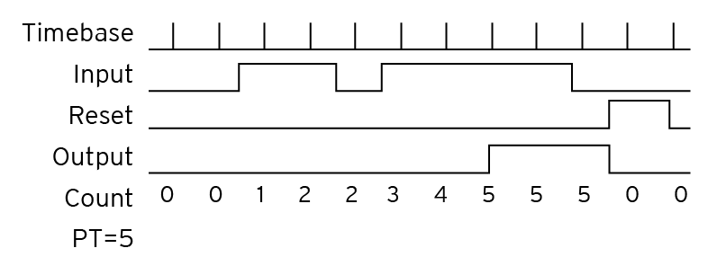
A timer is a PLC instruction measuring the amount of time elapsed following an event. Timer instructions come in two basic types: on-delay timers and off-delay timers. Both “on-delay” and “off-delay” timer instructions have single inputs triggering the timed function. The timer starts on a rising pulse of IN input. It stops when the Count up time (CT) is equal to programmed time (PT). A falling pulse of IN input resets the timer to 0. The output signal is set to TRUE when programmed time is elapsed, and reset to FALSE when the input command falls.
The timebase is user definable in 1mS, 10mS, 100mS and 1sec "ticks". When input IN goes high the counting proceeds based on the timebase block used.

Timer Configuration
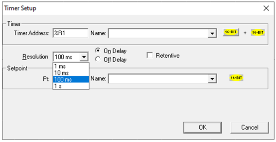
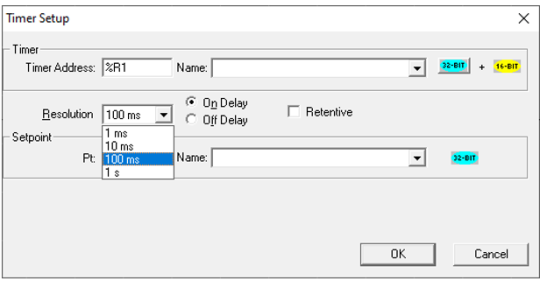
Note: Use the button marked 16 Bit/32 Bit to toggle the timer accumulator size. The default shown is 16-bit timer selection in YELLOW color and on clicking (toggling) this button the 32-bit timer is selected, the button color for which turns to AQUA. The button can be toggled again to go back to the previous accumulator size.
Timer Address - Type in the register to be used by this timer.
-
Each timer requires two (2) consecutive addresses if a 16-bit timer is selected.
-
Each timer requires three (3) consecutive addresses if a 32-bit timer is selected.
PT (Setpoint) - This is the timeout period expressed in timebase units.
-
For example, if the resolution (timebase value) is 100 milliseconds and the timeout value is "20", the timeout period is 2000 milliseconds or 2 seconds. This entry can also use a Register reference. If a register reference is entered then Each timer requires just one (1) address if a 16-bit timer is selected and, Each timer requires two (2) consecutive addresses if a 32-bit timer is selected. For example, if %R45 is entered in the box for PT, then the timer uses %R45 & %R46 if it is a 32-bit timer.
Resolution - This is the timebase value. Use the drop-down list to select one from 1 milliseconds, 10 milliseconds, 100 milliseconds or 1 second.
Register Usage - Each 16-bit Timer requires two (2) consecutive 16-bit registers (%R). They are arranged like so:
|
%Rx& |
Accumulator |
|
%Rx+1 |
Power |
Enabled |
Reserved |
|
|
**Bit 16 |
*Bit 15 |
Bit 14-1 |
* Bit 15 is not enabled during Timer OFF (TOF). Bit 15 also indicates power to the rung.
**Bit 16 indicates power flow through the timer function.
Each 32-bit Timer requires three (3) consecutive 16-bit registers (%R). They are arranged like so:
|
%Rx and %Rx+1& |
Accumulator |
|
%Rx+2 |
Power |
Enabled |
Reserved |
|
|
**Bit 16 |
*Bit 15 |
Bit 14-1 |
* Bit 15 is not enabled during Timer OFF (TOF). Bit 15 also indicates power to the rung.
**Bit 16 indicates power flow through the timer function.
Procedure
To configure the element, double click it, and then select the proper values from the configuration dialog box.
Timer 16-bit:
Timer 32-bit:
Power Flow
When power is supplied to the TON the output becomes inactive and the TON counts up to the preset value at a rate determined by the configured timebase. When the internal accumulator reaches the Preset Value, the output becomes active and counting stops. When power is removed from the element, the TON resets to zero.
When power is applied to the TOF Timer, the output immediately becomes active. When power is removed from the TOF the output stays active, and the TOF counts up to the preset value at a rate determined by the configured timebase. When the internal accumulator reaches the Preset Value, the output becomes inactive and counting stops. When power is supplied to the element, the TOF resets to zero.

Return to the Top: Timer in Advanced Ladder
On Delay Timer
With ON-delay operation, the timer receives an input and then an output signal is output by switching the Timer contacts after a set time delay. This name is used because there is a delay between when the input signal is received (i.e., turns ON) and when the output signal is output.
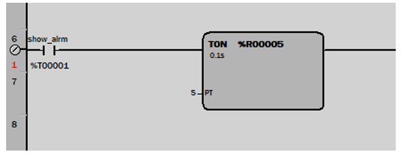
Note: Only the On Delay Timer is retentive (when power flow is removed from the element -it does not clear the elapsed time).
When power is supplied to the TON the output becomes inactive and the TON counts up to the preset value at a rate determined by the configured timebase. When the internal accumulator reaches the Preset Value, the output becomes active and counting stops. When power is removed from the element, the TON resets to zero.
The timebase is user definable in 1mS, 10mS, 100mS or 1S "ticks". When power is applied to the element, counting proceeds using this timebase.
Return to the Top: Timer in Advanced Ladder
Retentive On Delay Timer
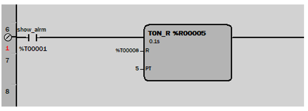
A Retentive On Delay Timer is a special case of the "standard" On Delay Timer, but differs from the standard timer in that the Retentive Timer does not reset when the input is brought inactive (off). The Retentive Timer requires that a reset signal be applied to the element in order for the timer to be reset.
Note: Resetting the Retentive Timer requires the use of a contact under software control of the controller.
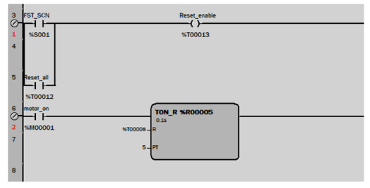
Since the Retentive Timer is retentive, any value appearing in registers assigned to the element can be invalid immediately after a download. One approach is to reset the timer in combination with the First Scan bit:
Return to the Top: Timer in Advanced Ladder
OFF Delay Timer
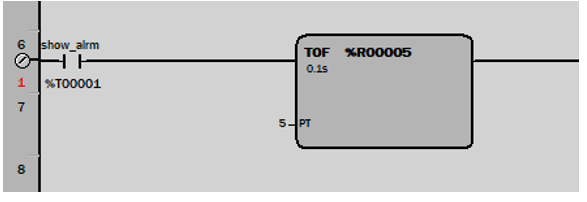
Off-delay timers (also known as delay-on-release, delay-on-break, or delay-on-energization timers) are ready to accept the trigger when the input voltage is applied. An output is energized by applying the trigger, which must be removed for the time delay to start.
Note: Only the On Delay Timer may be retentive (when power flow is removed from the element it does not clear the elapsed time).
When power is applied to the TOF Timer, the output immediately becomes active. When power is removed from the TOF the output stays active, and the TOF counts up to the preset value at a rate determined by the configured timebase. When the internal accumulator reaches the Preset Value, the output becomes inactive and counting stops.When power is supplied to the element, the TOF resets to zero.
The timebase is user definable in 1mS, 10mS, 100mS or 1S "ticks". When power is applied to the element, counting proceeds at this timebase.
Return to the Top: Timer in Advanced Ladder