Ethernet Configuration Overview
See also: Get Started with Cscape
Topic Menu
Downloadable Industrial Ethernet Protocols
Built-In (Resident) Industrial Protocols

|
Ethernet IP Communications |
|
|
OCS as Ethernet IP I/O Adapter |
|
|
Comparing Ethernet IP, Modbus TCP & Ethernet Global Data |
Return to the Top: Ethernet Configuration Overview
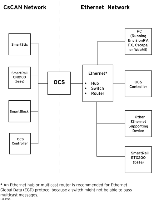
Ethernet Network Wiring
Return to the Top: Ethernet Configuration Overview
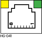
Installation
|
Green LED indicates link - when illuminated, data communication is available. Orange LED indicates activity - when flashing, data is in transmission. |
Note: Not all models use Green and Orange LED lights. Also, if a light is illumination (not flashing) this indicates that data communication. If a light is flashing, this indicates data is in transmission.
Network Administrator Installation Notes
When connecting an OCS to a local network, the following information is provided to the Network Administrator, as an aid in configuring Ethernet hubs, routers, switches, gateways, and servers.
UDP and TCP Ports
Each protocol supported by the OCS (except ICMP) uses one or more UDP![]() UDP - User Datagram Protocol - An alternative communications protocol to Transmission Control Protocol (TCP) used primarily for establishing low-latency and loss-tolerating connections between applications on the internet. and/or TCP
UDP - User Datagram Protocol - An alternative communications protocol to Transmission Control Protocol (TCP) used primarily for establishing low-latency and loss-tolerating connections between applications on the internet. and/or TCP![]() TCP - Transmission Control Protocol - A standard that defines how to establish and maintain a network conversation through which application programs can exchange data. Ports as the destination port for all messaging, as shown in table below. Required port usage for the supported protocols should be considered when configuring Ethernet routers and gateways.
TCP - Transmission Control Protocol - A standard that defines how to establish and maintain a network conversation through which application programs can exchange data. Ports as the destination port for all messaging, as shown in table below. Required port usage for the supported protocols should be considered when configuring Ethernet routers and gateways.
Note: Any port can be used as the source port.
| Ethernet Protocol UDP and TCP Port Usage | ||||
|---|---|---|---|---|
| Ethernet Protocol | UDP Port | TCP Port | ||
| Hexadecimal |
Decimal | Hexadecimal | Decimal | |
| EGD | 4746 | 18246 | ||
| STRP | 4745 | 18245 | ||
| Modbus | 01F6 | 502 | ||
| CsCAN over Ethernet | 4845 | 18501 | ||
| Ethernet / IP | 08AE | 2222 | AF12 | 44818 |
| FTP | 0014 and 0015 | 20 and 21 | ||
| HTTP (Standard and WebMI) | 0050 | 80 | ||
| HTTPS (WebMI only) | 01BB | 443 | ||
| SMTP | 0035 | 53 | 0019 | 25 |
| ICMP (Ping) | N/A | N/A | ||
| ASCII over TCP/IP | N/A | User Configurable | ||
Note: SMTP TCP port is user configurable, but in Home > Program > Messaging > Email feature if user selects 'Obtain SMTP Server IP Address from DNS Server' then UDP connection will be used to obtain Server IP, in such case UDP port 53 (Decimal) will be used.
Internet Connectivity
Since the OCS uses a standard TCP/IP![]() TCP/IP – Transmission Control Protocol / Internet Protocol - A transport layer protocol and a network layer protocol developed by the Department of Defense. This is a commonly used combination for communication within networks and across internetwork. protocol stack (powered by NetX and ThreadX), it can communicate beyond the local network, and on the internet, for all protocols except EGD. To do so, the OCS must be configured with the IP Address of a network gateway server, which allows communication outside the local network. See Default Gateway configuration under Step 5 of Section 3.1 in this manual for details.
TCP/IP – Transmission Control Protocol / Internet Protocol - A transport layer protocol and a network layer protocol developed by the Department of Defense. This is a commonly used combination for communication within networks and across internetwork. protocol stack (powered by NetX and ThreadX), it can communicate beyond the local network, and on the internet, for all protocols except EGD. To do so, the OCS must be configured with the IP Address of a network gateway server, which allows communication outside the local network. See Default Gateway configuration under Step 5 of Section 3.1 in this manual for details.
Note: As network complexity increases, due to Ethernet hubs, routers, switches, gateways, and the internet, the worst-case network delay increases. In many cases, the client software must be configured to account for this time lag. For example, Cscape’s Timeout can be adjusted, refer to [CsCAN over Ethernet ].
Important: Wireless Network Considerations
When using wireless equipment with industrial networks, make sure the system is designed and installed by personnel that have been trained to use wireless networks in industrial environments. Site surveys, selection of equipment, and installation can be critical in network performance.
In general, the 802.11b-based equipment is not a good choice in industrial environments. The frequencies and modulation techniques used in the “b” standard are very susceptible to multi-path interference in industrial environments (large metal objects, dense walls and floors, etc.) The 802.11a and 802.11g are less susceptible to this interference.
Using UDP![]() UDP - User Datagram Protocol - An alternative communications protocol to Transmission Control Protocol (TCP) used primarily for establishing low-latency and loss-tolerating connections between applications on the internet. based protocols, such as Ethernet Global Data (EGD), must be carefully considered when using wireless networks. Wireless networks are more likely to lose or damage communication packets. Many UDP based protocols, including EGD, do not detect and retransmit lost or damaged packets and depend on periodic data transmissions to compensate for this lost data. If your system requires a UDP protocol with a wireless network, make sure it is designed such that random periods without refreshed data do not adversely affect the operation of your system.
UDP - User Datagram Protocol - An alternative communications protocol to Transmission Control Protocol (TCP) used primarily for establishing low-latency and loss-tolerating connections between applications on the internet. based protocols, such as Ethernet Global Data (EGD), must be carefully considered when using wireless networks. Wireless networks are more likely to lose or damage communication packets. Many UDP based protocols, including EGD, do not detect and retransmit lost or damaged packets and depend on periodic data transmissions to compensate for this lost data. If your system requires a UDP protocol with a wireless network, make sure it is designed such that random periods without refreshed data do not adversely affect the operation of your system.
Depending on the architecture of the wireless network and the protocols used, wireless networks often produce collisions and extra data packets that are not experienced when using a traditional wire and switch-based network. The extra collisions and traffic coupled with the typically lower bandwidth![]() The range of frequencies over which a system is designed to operate. The bandwidth is expressed in Hertz between the highest and lowest frequencies. and higher latency of wireless networks can cause degradation in performance.
The range of frequencies over which a system is designed to operate. The bandwidth is expressed in Hertz between the highest and lowest frequencies. and higher latency of wireless networks can cause degradation in performance.
Return to the Top: Ethernet Configuration Overview
Ethernet Configuration 

Note: The following configuration is required for all applications regardless of the protocols used. Additional configuration procedures must be performed for each protocol used as described in the configuration sections of the next several chapters.
To configure the OCS, use Cscape programming software to perform the following steps:
-
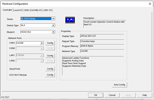
On the main Cscape screen, in the Program group, Hardware Configure .
-
Select OCS and OCS Model: click on the drop-down boxes for Series and Device Type and select the desired OCS model.
-
Click the Config button to the right of LAN1 for LAN 1 or LAN2 for LAN2, revealing the OCS Configuration dialog.
Note: Screen shot shows a typical Hardware Configuration dialog for OCS Models.
-
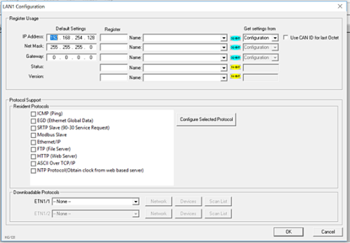
Configure the OCS parameters as follows using figure above as a reference.
Return to the Top: Ethernet Configuration Overview
Ethernet Register Usage
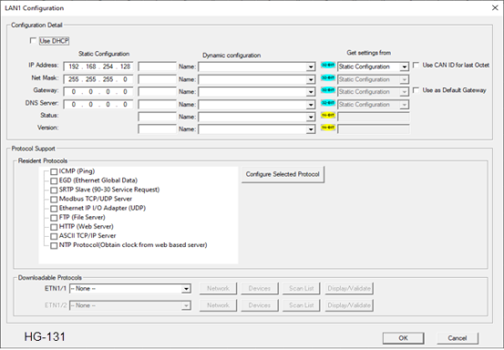
IP Address![]() IP Address - Internet Protocol - This is the address of a device on an Ethernet or Wi-Fi network. Horner controllers currently use IPv4 standards with addresses consisting of 4 numbers, or octets, separated by decimal points.: Enter the static IP Address for the OCS being configured.
IP Address - Internet Protocol - This is the address of a device on an Ethernet or Wi-Fi network. Horner controllers currently use IPv4 standards with addresses consisting of 4 numbers, or octets, separated by decimal points.: Enter the static IP Address for the OCS being configured.
Note: IP Addresses are entered as four numbers, each ranging from 0 to 255. These four numbers are called octets and they are always separated by decimal points.
Net Mask: Enter the Net Mask (sometimes called Subnet Mask) being used by all nodes on the local network. Typical local networks use Class C IP Addresses, in which case the low octet (rightmost number) is used to uniquely identify each node on the local network. In this case, the default Net Mask value of 255.255.255.0 should be used.
Gateway: Enter the IP Address of a Gateway Server on the local network that allows for communication outside of the local network. To prevent the OCS from communicating outside the local network, set the Default Gateway IP Address to 0.0.0.0 (the default setting).
Status Register: Enter an OCS Register reference (such as %R100) to indicate which 16-bit OCS register will have the Ethernet Status word written to it. The table shows how this register value is formatted and explains the meaning of each bit in the Status Word.
-
Version Register: Enter an OCS Register reference (such as %R101) to indicate which 16-bit OCS register will have the Ethernet Firmware Version written to it. The value stored in the Version Register is: (Ethernet Firmware Version * 100). For example, for Ethernet Firmware Version 4.30, the Version register will contain 430. For controllers with built-in Ethernet hardware, this Firmware Version is only changed when the Firmware for the OCS is updated
-
For the Status and Version registers (if configured), the Direction settings are always Read Only
-
Use CAN ID for last Octet: The Use CAN ID for last Octet checkbox does not affect Net Mask, Gateway, Status or Version configuration. If the checkbox is checked then it behaves as follows:
-
If the IP Address Direction combo box is Read / Write, the Use CAN ID for last Octet checkbox will be unchecked and grayed.
-
If the IP Address Direction combo box is empty or Read Only, the Use CAN ID for last Octet checkbox will be ungrayed and can then be unchecked or checked.
-
If the Use CAN ID for last Octet checkbox is checked, the unit’s 8-bit CAN Network ID replaces the last (rightmost) octet of the Default IP Address, and the combined result will be the unit’s IP Address. In this case, if the IP Address Register edit box contains a valid OCS register, the indicated register will be loaded with the combined IP Address.
-
OCS IP Address IP Address - Internet Protocol - This is the address of a device on an Ethernet or Wi-Fi network. Horner controllers currently use IPv4 standards with addresses consisting of 4 numbers, or octets, separated by decimal points.
The OCS obtains its IP Address in one of three different ways, depending on how the Use CAN ID for last Octet & IP Address direction checkboxes are configured, as described in the following three sections.
Static IP Address with CAN ID
In this mode, the OCS’s IP Address comes from a combination of the IP Address parameter and the OCS CAN Network ID. The most significant (leftmost) three octets of the IP Address come from the IP Address parameter. The least significant (rightmost) octet of the IP Address is taken from the OCS CAN Network ID. In this case the OCS writes the adjusted IP Address to the 32-bit OCS register indicated by the IP Address Register parameter.
Note: Every time a Hardware Configuration is successfully downloaded to an OCS with an OCS, the static IP Address, Net Mask and Default Gateway parameters are stored in non-volatile memory. In the event of a future unsuccessful I/O configuration download, the OCS will communicate using these 3 stored parameters. This is done to minimize potential loss of communication, which would require direct on-site intervention to correct.
Ethernet Configuration - IP Parameters
For primary operation, the IP address, Net Mask, and Gateway should be set in the LAN Config of the Cscape Hardware Configuration. There are options to get IP parameters from the LAN Config or to get parameters from registers. It is possible to set the Ethernet IP parameters from the OCS System Menu, but only as a temporary measure. The following points on IP parameter configuration should be considered.
-
IP Parameters in Non-Volatile RAM: The IP parameters of the Cscape LAN Config are written to non-volatile RAM on power down. IP parameter settings made in the System Menu are not written to non-volatile RAM. Any IP parameters settings made in the system menu will be lost after cycling power to the unit. It will revert to the last downloaded Cscape LAN Config that was loaded into non-volatile RAM at power down.
-
“Cscape LAN Config”/“Get Settings from” Static Configuration: When ‘Get settings from’ is set to Static Configuration, the IP parameters specified under ‘Default Settings’ is used after downloading to the controller. The IP parameters are represented in System Menu / Set Networks and can be edited. However, any edits made from System Menu / Set Networks is not retained through a power cycle. After power cycle, the unit reverts to the last downloaded Cscape LAN Config that was loaded into non-volatile RAM at power down.
-
“Cscape LAN Config”/“Get Settings from” Dynamic Configuration: When ‘Get settings from’ is set to Dynamic Configuration, the IP parameters are retrieved from the OCS registers assigned in LAN Config. Configured registers must be populated with the desired IP parameters.
-
The IP parameters are represented in System Menu/Set Networks.
-
The IP parameters cannot be edited from System Menu/Set Networks while the unit is in run mode.
-
The IP parameters always follow the values in the registers unless the OCS unit is placed in idle mode.
-
Then the IP parameters can be edited in System Menu/Set Networks. When the OCS is placed back into run mode, it reverts to the registers for IP parameters.
Return to the Top: Ethernet Configuration Overview
Use as Default Gateway
From Cscape 10.2 SP1 onwards, Default Gateway option has been implemented for XLPrime and Canvas Series (Supported from firmware ver 17.40 onwards for XLPrime and Canvas Series).
If a Default Gateway was configured on multiple interfaces (LAN1, LAN2, and Wi-Fi Client mode) at the same time, all interfaces tried to use a common routing path. This resulted in gateway conflicts, where only one interface (LAN1 or LAN2) maintained proper communication and the others failed to communicate. To eliminate routing conflicts and ensure stable network communication, “Use as Default Gateway” option has been implemented.
The system now manages gateway configuration efficiently by allowing only one active default gateway at a time.
Notes:
-
When the Default Gateway option is not explicitly enabled, the system automatically uses the LAN1 port as the default gateway interface.
-
“Use ad Default Gateway” checkbox is available in the LAN1, LAN2, and Wi-Fi Client mode configuration windows to allow gateway selection.
-
Once the Default Gateway option is enabled in any one interface configuration, the checkbox will automatically be disabled in the remaining configuration windows to ensure that only a single default gateway is active at a time.
Return to the Top: Ethernet Configuration Overview