Modbus TCP/IP Client
See also: Ethernet Configuration Overview
Topic Menu
Modbus TCP/IP Client Overview

|
Using Modbus TCP for OCS to OCS Communication |
Note: Each controller family has its own Modbus Mapping table. See the User Manual for an OCS to view a specific controller's Modbus table. Refer to the Documentation Search on the Horner website.
Modbus TCP/IP![]() TCP/IP – Transmission Control Protocol / Internet Protocol - A transport layer protocol and a network layer protocol developed by the Department of Defense. This is a commonly used combination for communication within networks and across internetwork. is a variant of the Modbus family of simple, vendor-neutral communication protocols. It is intended for supervision and control of automation equipment. Specifically, it covers the use of Modbus messaging in an ‘Intranet’ or ‘Internet’ environment using the TCP/IP protocols. The most common use of this protocol is for Ethernet attachment of PLC’s, I/O modules, and ‘gateways’ to other simple field buses or I/O networks.
TCP/IP – Transmission Control Protocol / Internet Protocol - A transport layer protocol and a network layer protocol developed by the Department of Defense. This is a commonly used combination for communication within networks and across internetwork. is a variant of the Modbus family of simple, vendor-neutral communication protocols. It is intended for supervision and control of automation equipment. Specifically, it covers the use of Modbus messaging in an ‘Intranet’ or ‘Internet’ environment using the TCP/IP protocols. The most common use of this protocol is for Ethernet attachment of PLC’s, I/O modules, and ‘gateways’ to other simple field buses or I/O networks.
Note: This is a Downloadable Industrial Protocol.
Modbus TCP![]() TCP - Transmission Control Protocol - A standard that defines how to establish and maintain a network conversation through which application programs can exchange data. is a Client/Server protocol, which allows a remote Modbus TCP Client to request services from a Modbus TCP Server. In this context, the OCS acts as a Modbus TCP Server, which responds to requests from one or more Modbus Clients. All Modbus requests that contain the OCS’s IP Address are serviced. The client needs to be configured with the OCS’s IP Address, and most clients also require the server unit number. Since each Ethernet module must have its own unique IP Address, the server unit number is not relevant and is discarded by the Ethernet module. To access OCS registers, a Modbus TCP Client must be configured with the appropriate register type and offset.
TCP - Transmission Control Protocol - A standard that defines how to establish and maintain a network conversation through which application programs can exchange data. is a Client/Server protocol, which allows a remote Modbus TCP Client to request services from a Modbus TCP Server. In this context, the OCS acts as a Modbus TCP Server, which responds to requests from one or more Modbus Clients. All Modbus requests that contain the OCS’s IP Address are serviced. The client needs to be configured with the OCS’s IP Address, and most clients also require the server unit number. Since each Ethernet module must have its own unique IP Address, the server unit number is not relevant and is discarded by the Ethernet module. To access OCS registers, a Modbus TCP Client must be configured with the appropriate register type and offset.
This is usually accomplished with one of two methods:
- Use either Traditional Modbus References or Expanded Modbus References, in which the high digit represents the register type and the lower digits represent the register offset (starting with register 1 for each type). Since only four Modbus register types (0, 1, 3, and 4) can be represented in this manner, the OCS’s Modbus implementation packs several OCS register types into each Modbus register type. Starting addresses of each OCS register type are shown in the Traditional Modbus Reference and Expanded Modbus Reference columns.
- The second method requires the Modbus TCP Client to be configured with a specific Modbus Command and Offset. The supported Modbus commands and the associated offsets are also illustrated in the tables below.
Return to the Top: Modbus TCP/IP Client
Configuring Modbus Client Device
The following are the steps for configuring Modbus Client with Cscape.
-
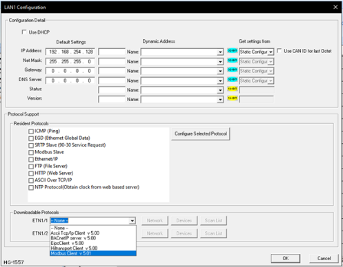
Open Home > Controller > Hardware Configuration (select a series and device type).
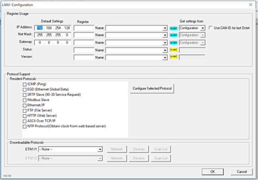
-
Select Config button next to LAN1/LAN2 . Downloadable Protocols and perform the following configurations: Select Modbus Client from the Downloadable Protocols/ETN1/1 drop-down list. Then click on the Network button. This will open the Network Config (Modbus Client) dialog.
Return to the Top: Modbus TCP/IP Client
Network Config (Modbus Client)
Home > Controller > Hardware Configuration > Downloadable Protocols > Modbus Client
Select Network button.
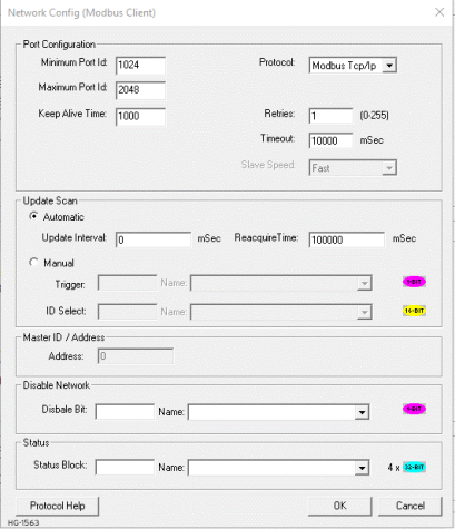
Network parameters and status registers can be configured in the Network Config dialog.
-
Configure minimum and maximum value for port ID’s as 1024 and 4096 respectively.
-
Configure the update Scan type as automatic or manual according to process requirements.
-
Configure the (optional) network status register.
-
Configure the (optional) disable network bit.
Return to the Top: Modbus TCP/IP Client
Device List (Modbus Client)
Home > Controller > Hardware Configuration > Downloadable Protocols > Modbus Client
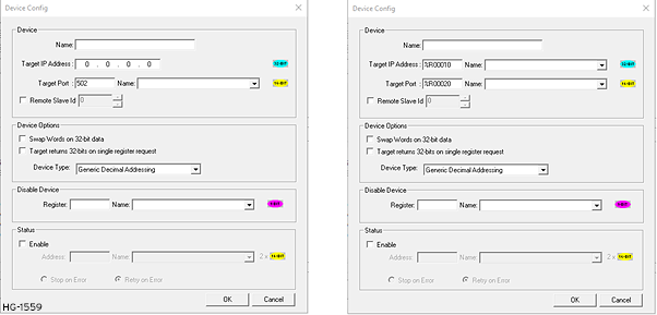
Select Devices button. The Devices button allows configuration of the Server device (max 64) as follows:
Select a device:
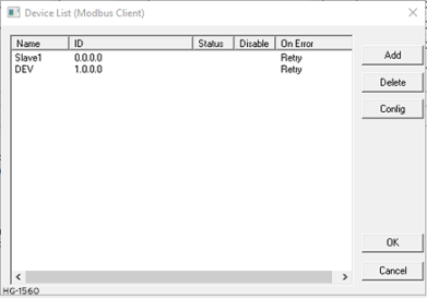
-
Configure server device name, IP address (either direct or through registers) and port ID (either direct or through registers). Configuring IP address or port ID through registers allows user to modify IP address or port ID during runtime.
Note: User should change the controller mode to Idle and then to Run after modifying port ID during runtime.
-
Select the address mode (refer to the Configuring Modbus Client Device ) required when talking to this device.
-
If option for Swap Words on 32-bit Data is checked, the high and low 16-bit values of 32-bit Data are swapped when transferred between the target and OCS.
-
Disable Device - From Cscape 9.90 SP3 and firmware 15.40 onwards, disable device feature has been added in protocol device configuration. This option is used to disable a particular slave configured in the network. Single bit register has to be configured to use this function.Setting the bit high disables the slave and OCS will not send any TCP packets only to this slave until the bit is high. Setting the bit low enables the communication with the slave again.
-
Device status registers can be optionally enabled and used to determine the current state of communications.
-
Select Stop on Error as per process requirement (located in the Status box at the bottom).
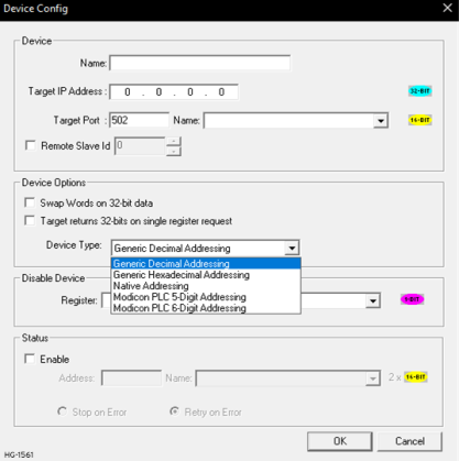
Device Type: Modbus TcpIpClient.Dll supports the following addressing modes:
-
Generic Decimal Addressing
-
Generic Hexadecimal
 A base-16 numbering system which uses the symbols 0, 1, 2, 3, 4, 5, 6, 7, 8, 9, A, B, C, D, E, F for numeral. Addressing
 -
Native Addressing
-
Modicon PLC 5-Digit Addressing
-
Modicon PLC 6-Digit Addressing
Generic Decimal Addressing
The first option is Generic Decimal Addressing. Use this when the connected device uses an addressing mode which does not correspond to a Modicon PLC, and offsets in the documentation for the target device are given in decimal.
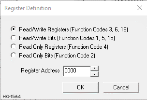
Addresses are entered in the following form:
<Data Type> <Decimal number>
Data type takes one of the following values:
RWR : (Read/Write Registers) Uses Modbus function codes 3, 6, 16
RWB : (Read/Write Bits) Uses Modbus function codes 1, 5, 15
ROR : (Read Only Registers) Uses Modbus function code 4
ROB : (Read Only Bits) Uses Modbus function code 2
The decimal number gives the offset of the target data in the selected data type.
Generic Hexadecimal A base-16 numbering system which uses the symbols 0, 1, 2, 3, 4, 5, 6, 7, 8, 9, A, B, C, D, E, F for numeral. Addressing
Use this when the connected device uses an addressing mode which does not correspond to a modicon PLC, and offsets in the documentation for the target device are given in hexadecimal.
Addresses are entering the in the following form:
<Data Type> <Decimal number>
Data type takes one of the following values:
RWR : (Read/Write Registers) Uses Modbus function codes 3, 6, 16
RWB : (Read/Write Bits) Uses Modbus function codes 1, 5, 15
ROR : (Read Only Registers) Uses Modbus function code 4
ROB : (Read Only Bits) Uses Modbus function code 2
The hexadecimal number gives the offset of the target data in the selected data type.
Native Addressing
Use this when the connected device is an OCS unit running Modbus TCP / IP host.
Addresses are entered as standard OCS addresses.
-
Modicon PLC 5-Digit Addressing - Use this when the connected device uses an addressing mode which corresponds to a reduced memory map modicon PLC.
-
Modicon PLC 6-Digit Addressing - Use this when the connected device uses an addressing mod which corresponds to an extended memory map modicon PLC.
Return to the Top: Modbus TCP/IP Client
Scan List
Home > Controller > Hardware Configuration > Downloadable Protocols > Modbus Client
Select Scan List![]() A list of communications to carry out to one or more devices. Normally, the Master or Client device will execute this scan list, which is directed at Slave or Server devices. Scan List items may be Polled or Triggered. button. The Scan List button opens the Scan List (Modbus Client) dialog.
A list of communications to carry out to one or more devices. Normally, the Master or Client device will execute this scan list, which is directed at Slave or Server devices. Scan List items may be Polled or Triggered. button. The Scan List button opens the Scan List (Modbus Client) dialog.
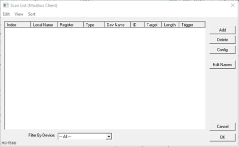
To transfer data between the OCS and remote target, a Scan List must be created that defines each transaction. Each mapping entry (transaction) contains the source and destination registers, the number of consecutive registers transferred, the direction of the transfer and trigger for transfer (optional). Maximum number of entries is 512.
Note: Order of the Scan List is the order in which the transaction occurs.
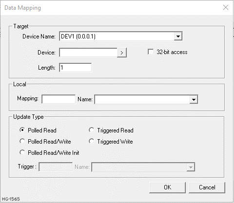
Scan List: Click ADD button to open the Data Mapping![]() Data mapping is the process of mapping data fields from a source file to their related target fields. dialog for adding new entry to the Scan List. Configure the following:
Data mapping is the process of mapping data fields from a source file to their related target fields. dialog for adding new entry to the Scan List. Configure the following:
| Data Mapping Fields | |
|---|---|
| Device Name |
Select the target device from the drop-down list. Only those device entries previously created from the Device Config menu are available. |
| Device |
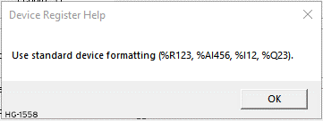
Specify the target device’s register to be mapped according to the selected addressing mode. See also: Configuring Modbus Client Device |
| 32-Bit Access |
Allows two local (OCS) 16-bit registers to be treated as a single 32-bit value. For example, if the value in either 16-bit register is modified, both registers are written to the device. |
| Length |
Specify the number of consecutive device registers to Read/Write. Maximum length is 32. |
| Local Mapping |
Specify the local (OCS) register that is the source or destination for transfer of the data. |
| Local Name |
(Optional) Enter/Select name for the Local Register. |
| Update Type |
This field specifies the direction and triggers the transfer of data between the OCS and target device. Select Update Type as per the system requirements. |
Refer to Modbus TCP/UDP server configuration (Modbus TCP Server Protocol (hornerautomation.com))
Connections
a. Media and Cabling
| Cable Specification |
Shielded and non-shielded twisted-pair 10/100Base-T cables with RJ45 connectors |
| Maximum Length Between 2 Stations |
100 meters (323 feet) |
b. Ethernet Connections
The Ethernet connector, Channel 1, is an RJ45, 10/100Base-T connector. The pin-out for the connector is shown below:
| Pin | Pin Name |
| 1 |
Tx+ |
| 2 |
Tx- |
| 3 | Rx+ |
| 4 | not used by 10/100 Base-T |
| 5 | not used by 10/100 Base-T |
| 6 | Rx- |
| 7 | not used by 10/100 Base-T |
| 8 | not used by 10/100 Base-T |

Network Communication Errors
In order to access the Network statistics, user must assign the “Network status register” in network configuration. The table below gives the details of statistics.
| Number | Statistics | Location | Description |
| 1 |
Update interval exceeded count |
%Rx |
This register explains number of times that the actual transaction scan time to complete all transactions exceeded specified update interval. Generally used as an indicator that an excessive number of triggered transfers or failed communication retries are occurring that is lengthening the expected transaction scan time. If the Update interval is set to zero (update as fast as possible), this 32-bit register alternately specifies the actual transaction scan time in mSec resolution. |
| 2 |
No response count |
%R(x+2) | This register explains number of times that a device(s) did not respond to a transaction. This includes ALL failed transaction, not just those after the retry count is exceeded |
| 3 | Corrupt response count | %R(x+4) | This register explains number of times that a device(s) returned an invalid or failed response to a transaction. This includes ALL failed Transaction, not just those after the retry count is exceeded |
| 4 | Valid response count | %R(X+6) | This register explains total number of valid responses |
NOTE:
1. %Rx: 32-bit network status register configured in Network configuration. For example: %R500(501).
2. When slave device ip is configured as 0.0.0.0, valid response count will increase. Reason being 0.0.0.0 is the loopback IP address also referred as the localhost. This address is used to establish an IP connection to the same device (similar to 127.0.0.1). Also Good response will be seen when Modbus server and client (Downloadable protocol) is configured in the same device.
| Error | Error Number | Description |
| ENET_LINK |
40 |
Ethernet Link is down |
| NODE_OFFLINEe |
45 |
Node is offline |
| INVALID_BLOCK | -203 | Invalid size for data type |
| NO_RESPONSE_FROM_PLC | -204 | Timeout while waiting for remote node response. (Device is connected to Slave node but not responding to Modbus queries) |
| INVALID_RESPONSE_FROM_PLC | -205 | Corrupted response from remote node |
| INVALID_INITIALIZATION | -207 | Internal Error - Unable to open port |
Return to the Top: Modbus TCP/IP Client