ASCII over TCP IP Protocol
See also: Ethernet Configuration Overview
Topic Menu
ASCII over TCP IP Protocol
This is the simplest communication protocol for text. It transmits only ASCII![]() ASCII - American Standard Code for Information Interchange - ASCII-coded characters are single-byte values in the range of 0 (zero) to 127. Codes in the range 128 to 255 are not defined by the ASCII standard, but rather by the equipment manufacturer.characters and uses ASCII
ASCII - American Standard Code for Information Interchange - ASCII-coded characters are single-byte values in the range of 0 (zero) to 127. Codes in the range 128 to 255 are not defined by the ASCII standard, but rather by the equipment manufacturer.characters and uses ASCII![]() ASCII - American Standard Code for Information Interchange - ASCII-coded characters are single-byte values in the range of 0 (zero) to 127. Codes in the range 128 to 255 are not defined by the ASCII standard, but rather by the equipment manufacturer.control codes. This downloadable protocol is in client mode and connects to specified server
ASCII - American Standard Code for Information Interchange - ASCII-coded characters are single-byte values in the range of 0 (zero) to 127. Codes in the range 128 to 255 are not defined by the ASCII standard, but rather by the equipment manufacturer.control codes. This downloadable protocol is in client mode and connects to specified server
ASCII Configuration
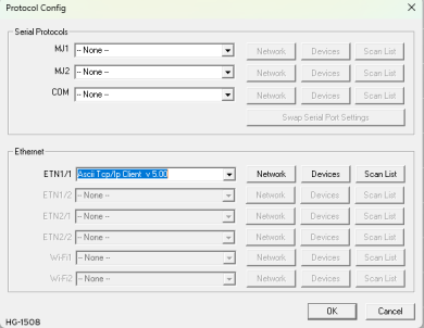
To configure controller for the ASCII TCP IP protocol, select the Protocol Configuration from the Programs menu in Cscape configurator. Select the appropriate protocol type. To make sure that the Software is able to configure the equipment for the correct protocol, ensure the AsciiTcpIpClient.dll file is in the Ethernet Protocols directory of the current working/opened configurator.
Network Configuration
After selecting the desired protocol, click on Network button which opens Network Config window as shown:
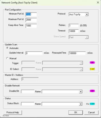
Configure the network parameters as shown above & click on Ok.
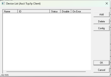
Device Configuration
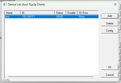
After network configuration, select "Devices" which opens up Device List window as shown:
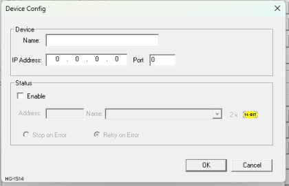
Clicking on theAdd button opens up the following dialog. Configure destination (Server) IP and port address as shown below & click on Ok.
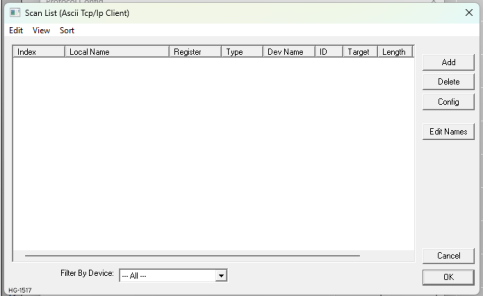
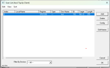
Scan List
Click on Scan List button to configure the scan list.
Clicking on the Add button opens up the data mapping window. Configure the fields as shown below & click on Ok.
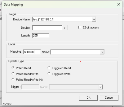
The count (Length) entered here is maximum data count which protocol needs to receive.
Features
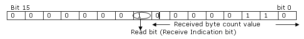
Receive (Read) Packet
User can configure protocol in Triggered read or polled read mode to receive data from server. Received byte count value is stored in first configured register and ‘Receive indication Bit’ will be set for indication purpose. Received ASCII characters will be Stored from Second Register onwards.
Example: If 6 ASCII characters are received then the content of the first register will be 0x0106 (in Hex).
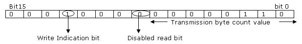
Send (Write) Packet
User can configure protocol in Triggered write mode to send data to the server. The lower byte of first register contains number of ASCII character to be send to server , write indication bit is to be set and Receive (read) indication bit is to be reset. ASCII character to be sent will be stored in Second register onwards.
Example: If 6 ASCII characters need to be send then content of the first register will be 0x1006 (in Hex).
Note: Following features are not supported:
- Termination Character: Due to design constraint terminating character in this protocol is not supported.
- Polled Read and Write Mode: Due to design constraint Polled Read and Write mode of data exchange is not supported. Currently the protocol switches to Write mode only when positive response is received for Read operation and vice versa.
- Status Register
Port Initializing
40
Invalid Size
-203
No Response from PLC
-204
Return to the Top: ASCII over TCP IP Protocol