Ethernet/IP Protocol
See also: Ethernet Configuration Overview
Topic Menu
Ethernet/IP Protocol

|
Ethernet IP Communications |

|
OCS as Ethernet IP I/O Adapter |

|
Comparing Ethernet IP, Modbus TCP & Ethernet Global Data |
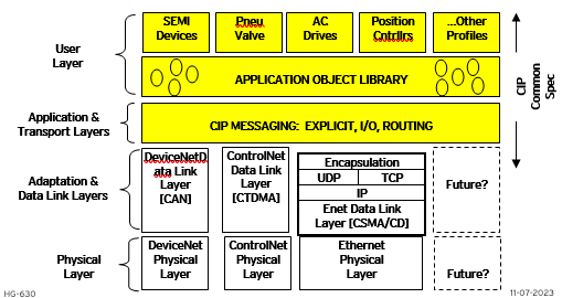
Ethernet/IP protocol is ODVA’s Common Industrial Protocol (CIP) over Ethernet. The figure below illustrates the protocol layers. Ethernet/IP starts at the Ethernet Physical Layer, and moves up through the IP, TCP![]() TCP - Transmission Control Protocol - A standard that defines how to establish and maintain a network conversation through which application programs can exchange data./UDP
TCP - Transmission Control Protocol - A standard that defines how to establish and maintain a network conversation through which application programs can exchange data./UDP![]() UDP - User Datagram Protocol - An alternative communications protocol to Transmission Control Protocol (TCP) used primarily for establishing low-latency and loss-tolerating connections between applications on the internet., and Encapsulation Layers. It is beyond the scope of this supplement to discuss the specifics of the Ethernet/IP protocol. See the Ethernet/IP specification at https://www.odva.org/ for more details of the Ethernet/IP protocol.
UDP - User Datagram Protocol - An alternative communications protocol to Transmission Control Protocol (TCP) used primarily for establishing low-latency and loss-tolerating connections between applications on the internet., and Encapsulation Layers. It is beyond the scope of this supplement to discuss the specifics of the Ethernet/IP protocol. See the Ethernet/IP specification at https://www.odva.org/ for more details of the Ethernet/IP protocol.
Note: This is a Built-In (Resident) Industrial Protocol.
The OCS provides Ethernet/IP server capability, and implements the following CIP objects:
| Identity | > |
Instance #1 |
| Connection Manager | > | Instance #1 |
| Message Router | > | Instance #1 |
| Assembly | > | Instance #100 (0x64) for Consumed Data |
| Assembly | > | Instance #100 (0x65) for Produced Data |
| TCP/IP | > | Instance #1 |
| Ethernet Link | > | Instance #1 |
The OCS has an Unconnected Message Manager (UCMM), which forwards the following services on to the addressed object:
-
Forward Open (Connection Manager object service)
-
Forward Close (Connection Manager object service)
-
Get Attribute Single
-
Set Attribute Single
It will forward the above services on to the addressed object, however the addressed object may or may not support the service. The OCS supports Class 3 connections for explicit messaging, and Class 1 connections for I/O (Implicit) messaging. The OCS can be configured to produce and consume 0 bytes of data up to 256 bytes of data. The TCP connections used for Ethernet/IP have an inactivity timeout of 60 seconds. In the event of an inactivity timeout, the TCP connection will automatically close.
Return to the Top: Ethernet/IP Protocol
Ethernet/IP Configuration
If Ethernet/IP protocol will be used in the application, Ethernet/IP configuration must be performed, in addition to the general Ethernet LAN1 Configuration previously described in Chapter 3. To configure Ethernet/IP protocol, use Cscape Programming Software to perform the following five steps:
-
Open the Ethernet LAN1 Configuration dialog (Home > Hardware Configuration > LAN1/Config).
-
Enable Ethernet/IP by checking the Ethernet IP checkbox.
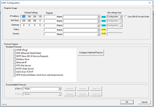
-
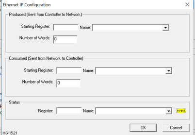
Click on the Configure Selected Protocol button next to the Ethernet/IP checkbox to open the Ethernet IP Configuration dialog.
-
Set the location and size of Produced and Consumed data.
-
Also, set the location of the 16-bit Ethernet/IP Status word.
Return to the Top: Ethernet/IP Protocol
Ethernet/IP Operation
After configuring the OCS, it is ready to respond to Ethernet/IP requests. The OCS handles unconnected requests anytime.
To exchange I/O data with the OCS, a class 1 connection pair must be established. The connection pair consists of a class 1 originator-to-target connection and a class 1 target-to-originator connection, both of which should be set for point-to-point Transport Type. The data sizes must match the OCS’s configured Consumed and Produced data sizes, respectively. The application path should be set as follows:
-
The originator-to-target connection point should be set to 100 (0x64), which stands for the assembly class (4), instance 100 (0x64).
-
The target-to-originator connection point should be set to 101 (0x65), which stands for the assembly class (4), instance 101 (0x65).
There is NO configuration assembly instance. All the class 1 connection pair setup data is transmitted through a forward open service to the connection manager. Once the class 1 connection pair is established, I/O data is exchanged to/from the OCS through these connections. The Consumed data (data coming from the scanner) and Produced data (data going to the scanner) are available at the locations within the OCS register map as configured.
The TCP connections used for all encapsulated messages and explicit messages have an inactivity timeout of 60 seconds. If the TCP connections are required to stay open, a NOP encapsulated command can be used at a periodic rate to keep the TCP connection open.
When the OCS is not is RUN mode, Produced data is all zeros, and Consumed data is not written to the configured registers within the OCS. When the OCS is in RUN mode, the configured Produced OCS registers are read and sent as Produced data, while Consumed data is received and written to the configured Consumed OCS registers.
The Status word provides Ethernet/IP connection status. The upper byte of the word contains the Class 3 (Explicit) connection count and the lower byte contains the Class 1 (IO) connection count.
Note: When the Status word indicates no connections, the Consumed OCS registers contain old data.
Return to the Top: Ethernet/IP Protocol