ASCII over TCP/IP
See also: Ethernet Configuration Overview
Topic Menu
ASCII over TCP/IP Overview
This protocol is designed to send and receive ASCII![]() ASCII - American Standard Code for Information Interchange - ASCII-coded characters are single-byte values in the range of 0 (zero) to 127. Codes in the range 128 to 255 are not defined by the ASCII standard, but rather by the equipment manufacturer. data over Ethernet port of the controllers. Controller acts as a server while using this protocol.
ASCII - American Standard Code for Information Interchange - ASCII-coded characters are single-byte values in the range of 0 (zero) to 127. Codes in the range 128 to 255 are not defined by the ASCII standard, but rather by the equipment manufacturer. data over Ethernet port of the controllers. Controller acts as a server while using this protocol.
Minimum version requirements for ASCII over TCP/IP:
-
Firmware 12.6 or later
-
Cscape 9 or later
ASCII Configuration
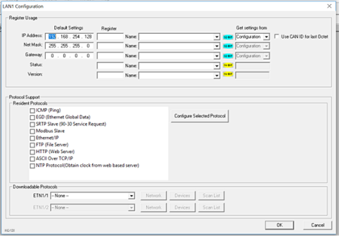
Step 1: Open CSCAPE and click on Home > Controller > Hardware Configuration (select a series and device type) > LAN1/Config button. In LAN1 configuration window set up IP address, Net mask, Gateway, and select ASCII over TCP/IP checkbox and the click on Configure Selected Protocol as shown below:
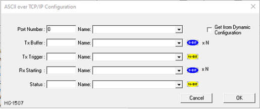
Step 2: In ASCII over TCP/IP![]() TCP/IP – Transmission Control Protocol / Internet Protocol - A transport layer protocol and a network layer protocol developed by the Department of Defense. This is a commonly used combination for communication within networks and across internetwork. Configuration window configure Port Number, register for start address of Transmit data, register for start address for Receive data, Transmission Trigger Register and Status Address. Port Number can be provided directly or by using register address. For port number entry using register user has to select Get from Dynamic Configuration option.
TCP/IP – Transmission Control Protocol / Internet Protocol - A transport layer protocol and a network layer protocol developed by the Department of Defense. This is a commonly used combination for communication within networks and across internetwork. Configuration window configure Port Number, register for start address of Transmit data, register for start address for Receive data, Transmission Trigger Register and Status Address. Port Number can be provided directly or by using register address. For port number entry using register user has to select Get from Dynamic Configuration option.
LAN1 > ASCII over TCP/IP > Configure Selected Protocol
Return to the Top: ASCII over TCP/IP
Sending ASCII Character to the Client
In above configuration dialog %R800 and %R100 registers are configured for sending data. %R800 is start of transmit data and should contain data in following format.
Note: Maximum 2K ASCII characters can be sent in a single request.
%R100 is Transmit Trigger register used to start the transmission process. Setting R100 data to ‘1’ will initiate transmission process and on successful transmission firmware will reset the R100 data to ‘0’.
Return to the Top: ASCII over TCP/IP
Receiving ASCII Characters from the Client
In above configuration dialog %R500 register is used for receiving data. The receive data register format will be as below.
Note: Maximum 2K ASCII characters can be received in a single request.
Status Information
%R700 register is used for to display status information. Details of Status Register as below.
Return to the Top: ASCII over TCP/IP