Ethernet Global Data Protocol (EGD)
See also: Ethernet Configuration Overview
Topic Menu

|
Hands-on with Ethernet Global Data Protocol |
|
|
Ethernet IP Communications |

|
OCS as Ethernet IP I/O Adapter |

|
Comparing Ethernet IP, Modbus TCP & Ethernet Global Data |
Note: This is a Built-In (Resident) Industrial Protocol.
Ethernet Global Data (EGD) protocol is a GE Fanuc Automation protocol, which is designed for simple, efficient data exchanges between peer devices on a network. EGD protocol communicates using the UDP![]() UDP - User Datagram Protocol - An alternative communications protocol to Transmission Control Protocol (TCP) used primarily for establishing low-latency and loss-tolerating connections between applications on the internet. transport layer. Although this method of data transfer is very efficient, it has no specific way to detect and recover lost data packets. However, since all EGD data transfers are periodic, lost data packets will be repeated when their user-configured time periods expire.
UDP - User Datagram Protocol - An alternative communications protocol to Transmission Control Protocol (TCP) used primarily for establishing low-latency and loss-tolerating connections between applications on the internet. transport layer. Although this method of data transfer is very efficient, it has no specific way to detect and recover lost data packets. However, since all EGD data transfers are periodic, lost data packets will be repeated when their user-configured time periods expire.
Caution: EGD protocol is not intended for one-time event notification or for applications with critical data, which cannot withstand being delayed as described above.
Each device on an EGD network can be configured as a Producer, as a Consumer, or both.
-
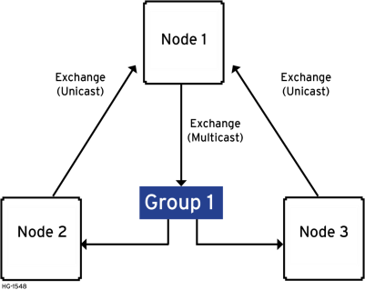
A Producer is a device that transmits Exchanges (blocks of data) to one or more Consumers. A Producer can transmit Exchanges directly to a specific Consumer, by sending them to the Consumer’s IP Address. (This is Unicast IP Addressing.) A Producer can also transmit Exchanges to a Group of Consumers, by sending them to a Group ID. (This is Multicast IP Addressing.) SeeEGD Unicast and Multicast IP Addressing for more details regarding Unicast and Multicast IP Addressing.
-
A Consumer is a device that receives Exchanges from one or more Producers. An OCS supports up to 127 concurrent Exchanges, each of which can be either a Producer or a Consumer of data.
EGD Terminology
Before configuring an OCS for EGD protocol, it is essential that the application programmer understand the key EGD terms.
| EGD Terminology | |
|---|---|
| Term | Definition |
| Exchange |
A block of data sent by a Producer and received by one or more Consumers |
| Exchange Number |
A number (1 to 16,383), which along with the IP Address of the Producer, is used to uniquely identify an Exchange on an EGD network |
| Producer | An EGD network device configured to transmit one or more Exchanges |
| Consumer | An EGD network device configured to receive one or more Exchanges |
| Produced Exchange | A block of data that a Producer sends to a Consumer or to a Group of Consumers |
| Consumed Exchange | A block of data that a Consumer or Group of Consumers receives from a Producer |
| Group |
One or more Consumers that are configured to receive Exchanges, which have been sent by a Producer to a specific Group ID |
| Group ID | A number (1 to 32), which is used to identify a Group of Consumers |
| Production Period | A value (in milliseconds) that specifies how often a Produced Exchange is transmitted to the network |
| Update Timeout |
A value (in milliseconds) that specifies how long a Consumer will wait to receive an Exchange, before considering it late. Note: In general, a Consumed Exchange’s Update Timeout is normally set to at least twice the corresponding Produced Exchange’s Production Period, plus 10ms. |
| Unicast |
Peer-to-peer communication in which data is sent to a SINGLE device at a specific IP Address. |
| Multicast |
Peer-to-peer communication in which data is sent to a GROUP IP Address, and all devices in that group will receive the data. |
Return to the Top: Ethernet Global Data Protocol (EGD)
EGD Configuration
If EGD protocol will be used in the application, EGD Configuration must be performed, in addition to the general OCS Configuration previously described in Ethernet Configuration Overview. To configure EGD protocol, use Cscape Programming Software to perform the following six steps:
Step 1: Open the OCS Configuration dialog: Home > Hardware Configuration > Config (LAN1 or LAN2).
Home > Hardware Configuration > LAN1 Configuration
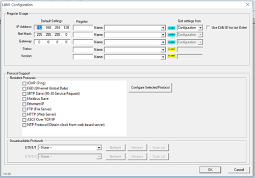
Step 2: Enable EGD by checking the EGD (Ethernet Global Data) checkbox in the LAN1 (or LAN2) Configuration dialog.
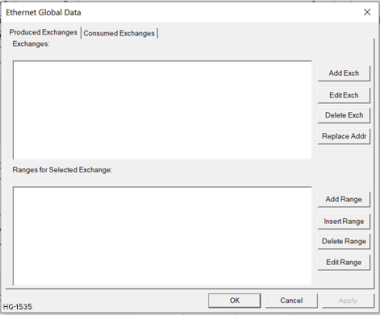
Step 3: Click on the Configure Selected Protocol button after selecting EGD (Ethernet Global Data) to open the Ethernet Global Data dialog.
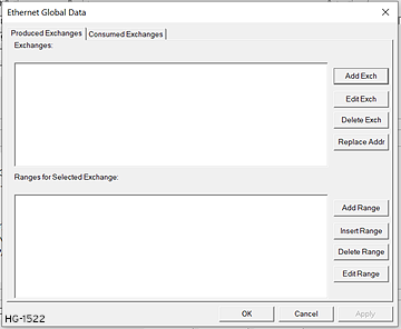
Note: The Ethernet Global Data dialog allows EGD Produced and Consumed Exchanges to be configured. To configure Produced Exchanges, select the Produced Exchanges tab; to configure Consumed Exchanges, select the Consumed Exchanges tab. Refer to image below.
Step 4: Follow the steps in EGD Produced Exchange Configuration to configure Produced Exchanges, as necessary for the application.
Step 5: Follow the steps in EGD Consumed Exchange Configuration to configure Consumed Exchanges, as necessary for the application.
Step 6: Click OK to accept the new EGD Configuration.
Return to the Top: Ethernet Global Data Protocol (EGD)
EGD Produced Exchange Configuration
| Produced Exchange Unicast & Multicast | |
|---|---|
| Unicast | To configure a unicast communication, use the IP address of the other device. |
| Multicast | To configure a multicast communication, use a Group Number. |
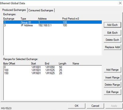
To configure EGD Produced Exchanges, open the Ethernet Global Data Configuration dialog as described in EGD Configuration , and select the Produced Exchanges tab, where:
-
In the upper window, one or more Produced Exchanges can be created.
-
In the lower window, I/O Blocks can be defined for each Produced Exchange.
When creating a Produced Exchange, the application programmer selects an Exchange Number for it, determines whether the Exchange will be sent to a specific Consumer or to a Group of Consumers, chooses which Consumer or Group of Consumers will receive the Exchange, and sets how often the Exchange will be sent to the EGD network.
When defining I/O Blocks for a Produced Exchange, the application programmer selects what type and how much information will be associated with the Exchange. For Produced Exchanges, there are two types of I/O Blocks to choose from: Data and Status. Refer to table below:
When defining Data Blocks for a Produced Exchange, the maximum total OCS register data the Exchange can send to the EGD network is 1400 bytes. This means that up to a total of 700 16-bit registers (%R![]() Retentive 16-bit registers., %AI
Retentive 16-bit registers., %AI![]() 16-bit input registers used to gather analog input data such as voltages, temperatures, and speed settings coming from an attached device., AQ, etc.), or 11,200 1-bit registers (%M, %T
16-bit input registers used to gather analog input data such as voltages, temperatures, and speed settings coming from an attached device., AQ, etc.), or 11,200 1-bit registers (%M, %T![]() Non-retentive single-bit registers., %I
Non-retentive single-bit registers., %I![]() Single-bit input registers. Typically, an external switch is connected to the registers., %Q, etc.), or a combination thereof can be defined for a Produced Exchange. NOTE: The OCS allows a total of up to 256 Data Blocks to be defined for all Produced Exchanges combined. This means that if 127 Produced Exchanges are configured, each can have an average of about 2 Data Blocks defined.
Single-bit input registers. Typically, an external switch is connected to the registers., %Q, etc.), or a combination thereof can be defined for a Produced Exchange. NOTE: The OCS allows a total of up to 256 Data Blocks to be defined for all Produced Exchanges combined. This means that if 127 Produced Exchanges are configured, each can have an average of about 2 Data Blocks defined.
When a Status Block is defined for a Produced Exchange, exactly 2 bytes of register data are written with the Produced Exchange’s Status Word. See EGD Status Words for general information regarding EGD Status Words, and EGD Produced Exchange Status Words for specific information regarding EGD Produced Exchange Status Words.
Note: The OCS maintains just one 16-bit status word for each Produced Exchange. For this reason, there is never any need to define more than one Status Block for a given Produced Exchange.
Return to the Top: Ethernet Global Data Protocol (EGD)
Creating EGD Produced Exchanges: Unicast & Multicast
To create unicast or multicast EGD Produced Exchanges, perform the following six steps:
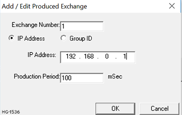
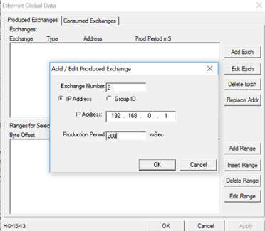
Step 1a: To configure a Unicast communication: After checking the EGD (Ethernet Global Data Protocol box in the LAN Configuration dialog, click on the Add Exch button to open the Add / Edit Produced Exchange dialog. Select the destination Address and enter information.
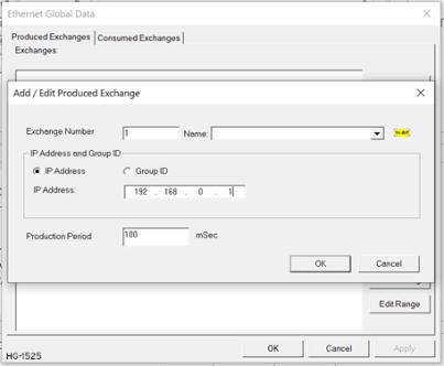
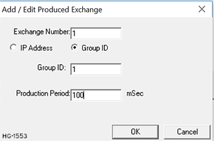
Step 1b:To configure a MULTICAST communication: After checking the EGD (Ethernet Global Data Protocol box in the LAN Configuration dialog, click on the Add Exch button to open the Add / Edit Produced Exchange dialog. Refer to EGD Produced Exchange Configuration . Select and assign Group ID.
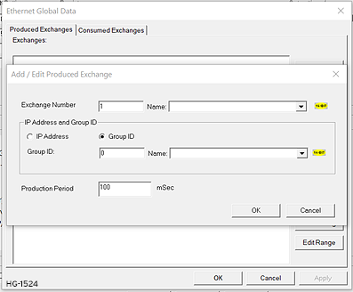
Step 2: Configure the Produced Exchange parameters as follows:
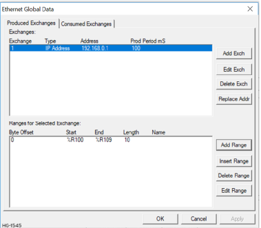
Step 3: Click OK to accept the new Produced Exchange configuration, which will be now be displayed in the upper window of the Ethernet Global Data dialog. Refer to EGD Configuration .
Step 4: To add another Produced Exchange to the list, click on the Add Exch button again.
Step 5: To edit or delete a Produced Exchange, highlight it in the upper window of the Ethernet Global Data Configuration dialog, and then click on the Edit Exch button or the Delete Exch button.
Step 6: To quickly change the IP Address in multiple Produced Exchanges, click on the Replace Addr button. This will open a dialog to allow the user to search and replace the IP Address parameter, in all Produced Exchanges simultaneously.
Return to the Top: Ethernet Global Data Protocol (EGD)
Defining EGD Produced Exchange I/O Blocks
After creating a Produced Exchange, one or more I/O Blocks should be defined for it. An I/O Block specifies what type and how much information will be associated with the Produced Exchange. To define I/O Blocks for a Produced Exchange, perform the following six steps:
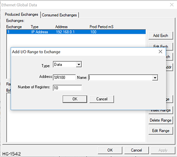
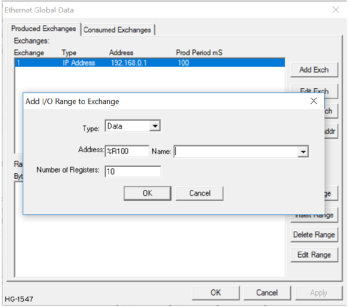
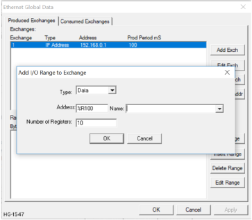
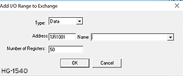
Step 1: In the upper window of the Ethernet Global Data dialog, refer to EGD Configuration , highlight one of the Produced Exchanges, and then click the Add Range button to open the Add I/O Range to Exchange dialog.
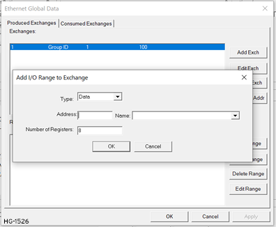
Step 2: Configure the I/O Block parameters as follows:
Step 3 Click OK to accept the Produced Exchange’s new I/O Block, which will be now be displayed in the lower window of the Ethernet Global Data Configuration dialog. Refer to EGD Produced Exchange Configuration .
Note: The OCS registers, specified in Data Block definitions, are sent to the EGD network in top-to-bottom order, as they appear in the lower window of the Ethernet Global Data Configuration dialog.
Step 4: To add another I/O Block, click the Add Range button again and repeat steps 2 and 3. The new I/O Block will appear at the end of the list.
Step 5: To insert an I/O Block into the middle of the list, highlight one of the I/O Block items in the list and then click on the Insert Range button. In this case, the new I/O Block will be inserted just before the highlighted I/O Block.
Step 6: To edit or delete an I/O Block in the list, highlight it and then click on the Edit Range or Delete Range button.
Return to the Top: Ethernet Global Data Protocol (EGD)
EGD Consumed Exchange Configuration
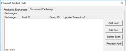
To configure EGD Consumed Exchanges, open the Ethernet Global Data Configuration dialog, and select the Consumed Exchanges tab.
-
In the upper window, one or more Consumed Exchanges can be created).
-
In the lower window, I/O Blocks can be defined for each Consumed Exchange.
When creating a Consumed Exchange, the application programmer selects an Exchange Number for it, determines whether to receive the Exchange as a single Consumer or as a member of a Group of Consumers, chooses which Producer to receive the Exchange from, and sets how often to expect the Exchange to be received.
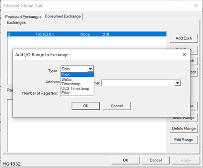
When defining I/O Blocks for a Consumed Exchange, the application programmer selects what type and how much information will be associated with the Exchange. For Consumed Exchanges, there are five types of I/O Blocks to choose from: Data, Status, Timestamp, OCS Timestamp, and Filler. The table shows these I/O Block Types along with their definitions:
| Consumed Exchange I/O Block Type Definitions | |
|---|---|
| Type | Definition |
| Data Block |
Block of consecutive OCS registers to be written with received data. When defining Data Blocks for a Consumed Exchange, the maximum total OCS register data the Exchange can receive from the EGD network is 1400 bytes. This means that up to a total of 700 16-bit registers (%R Note: The OCS allows a total of up to 256 Data Blocks to be defined for all Consumed Exchanges combined. This means that if 127 Consumed Exchanges are configured, each can have an average of about 2 Data Blocks defined. |
| Status Block |
16-bit OCS register to be written with the Consumed Exchange’s status word. When a Status Block is defined for a Consumed Exchange, exactly 2 bytes of register data are written with the Consumed Exchange’s Status Word. See also: EGD Status Words or EGD Consumed Exchange Status Words. |
| Timestamp Block |
Exactly 8 bytes of register data will be written with two 32-bit binary time stamp values, containing the numbers of seconds and nanoseconds since January 1, 1970. Note: The binary Timestamp Block is rarely used, and there is never any need to define more than one Status Block or OCS Timestamp Block for a given Consumed Exchange. |
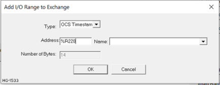
| OCS Timestamp Block |
Exactly 14 bytes of register data will be written with a 7-word OCS-format time stamp, consisting of second, minute, hour, day, month, year, and millisecond words. This OCS Timestamp can be displayed on the OCS screen, can be loaded into the OCS time-of-day clock, and can be more easily processed by ladder logic. |
| Filler Block |
Specifies a block of received data to ignore (skips unwanted data). |
Creating EGD Consumed Exchanges
To create EGD Consumed Exchanges, perform the following six steps:
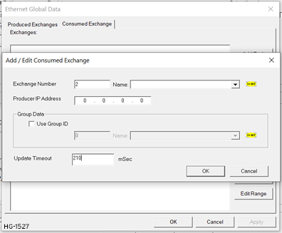
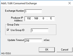
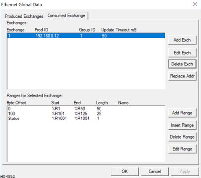
Step 1: In the Ethernet Global Data Configuration dialog, click on the Add Exch button to open the Add / Edit Consumed Exchange dialog. Refer to image below.
Step 2: Configure the Consumed Exchange parameters as follows:
Step 3: Click OK to accept the new Consumed Exchange configuration, which will be now be displayed in the upper window of the Ethernet Global Data Configuration dialog.
Step 4: To add another Consumed Exchange to the list, click on the Add Exch button again.
Step 5: To edit or delete a Consumed Exchange, highlight it in the upper window of the Ethernet Global Data Configuration dialog, and then click on the Edit Exch or Delete Exch button. Refer to EGD Configuration .
Step 6: To quickly change the Producer IP Address in multiple Consumed Exchanges, click on the Replace Addr button. This will open a dialog to allow the user to search and replace the Producer IP Address parameter, in all Consumed Exchanges simultaneously.
Return to the Top: Ethernet Global Data Protocol (EGD)
Defining EGD Consumed Exchanged I/O Blocks
After Creating EGD Consumed Exchanges, one or more I/O Blocks should be defined for it. An I/O Block specifies what type and how much information will be associated with the Consumed Exchange. To define I/O Blocks for a Consumed Exchange, perform the following six steps:
Step 1: In the upper window of the Ethernet Global Data Configuration dialog, highlight one of the Consumed Exchanges, and then click the Add Range button to open the Add I/O Range to Exchange dialog.
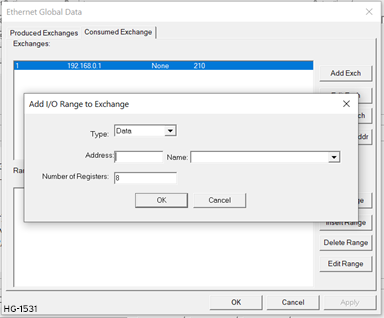
Step 2: Configure the I/O Block parameters as follows:
Step 3: Click OK to accept the Consumed Exchange’s new I/O Block, which will be now be displayed in the lower window of the Ethernet Global Data dialog.
Note: The OCS registers, specified in Data Block definitions, are filled with received data in top-to-bottom order, as they appear in the lower window of the Ethernet Global Data dialog. In this respect, Filler Blocks are placeholders for Data Blocks and can be thought of as Data Blocks whose received data bytes are discarded.
Step 4: To add another I/O Block, click on the Add Range button again and repeat steps 2 and 3. The new I/O Block will appear at the end of the list.
Step 5: To insert an I/O Block into the middle of the list, highlight one of the I/O Block items in the list and then click on the Insert Range button. In this case, the new I/O Block will be inserted just before the highlighted I/O Block.
Step 6: To edit or delete an I/O Block in the list, highlight it and then click on the Edit Range or Delete Range button.
Return to the Top: Ethernet Global Data Protocol (EGD)
Adding an OCS Time Stamp Block Configuration
In EGD protocol, a time stamp is sent with every Produced Exchange, indicating when the Producer sampled the data being sent. For a Consumer of the Exchange to get this information into an OCS register, define an OCS Timestamp Block for the Consumed Exchange. Perform the following 2 steps:
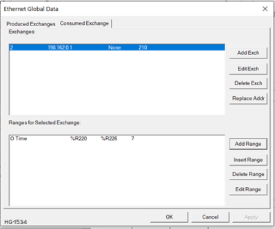
Step 1: In the EGD Configuration dialog, select the Consumed Exchanges tab.
Step 2: Make sure an exchange is highlighted in the upper and click on the Add Range button, to define an OCS Timestamp Block for Consumed Exchange. Then fill in the parameters, as shown in below, and click OK.
Return to the Top: Ethernet Global Data Protocol (EGD)
Filler Block Configuration
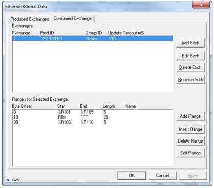
Sometimes a Consumer does not need all of the data sent by a Producer in an Exchange. In this case, the Consumed Exchange’s Data Block should be defined to receive fewer registers than will be sent by the Producer of the Exchange. However, if the partial data needed by the Consumer is not at the beginning of the data received in an Exchange, there must be some way to skip (ignore) the extra data. For this reason, the Ethernet Module supports Filler Blocks for Consumed Exchanges.
A Filler Block is used to skip unwanted data sent by the Producer. For example, if the Producer sends 40 data bytes in an Exchange, and the Consumer only needs the first and last 10 bytes, a Filler Block would be defined, in the appropriate slot in the list, to skip the middle 20 bytes of data.
Filler Produced Exchange Example: Controller A (IP 192.168.0.1)
Filler Consumed Exchange Example: Controller B (IP 192.168.0.2)
Note: The filler is used to skip the middle 20 bytes of Exchange 1.
Return to the Top: Ethernet Global Data Protocol (EGD)
EGD Unicast and Multicast IP Addressing
When using Ethernet Global Data (EGD) protocol for peer-to-peer communication, there are two methods for sending data: (1) send to a single device or (2) send to a group of devices. Refer to EGD Terminology
-
Unicast - When sending to a single device (method 1), EGD protocol uses Unicast IP Addressing. This means that the IP header’s 32-bit Destination IP Address will contain the intended recipient’s unique IP Address.
-
Multicast - When sending to a group of devices (method 2), EGD protocol uses Multicast IP Addressing. This means that the IP header’s 32-bit Destination IP Address will contain one of the 32 Multicast IP Addresses, refer to table.
| EGD Multicast IP Addressing | |
|---|---|
| Group ID | Multicast IP Address |
| 1 |
224.0.7.1 |
| 2 | 224.0.7.2 |
|
- - - |
- - - |
| 32 | 224.0.7.32 |
Ethernet Switches normally do not support Multicast IP Addressing, while Ethernet Hubs do support Multicast IP Addressing. Some Ethernet Routers, known as Multicast Routers, do support Multicast IP Addressing, by using Internet Group Management Protocol (IGMP).
Note: For those customers wanting to use Multicast Routers to connect EGD devices, the OCS automatically handles IGMP communication with Multicast Routers.
EGD Status Words
EGD Status Words allow an Ethernet Global Data user to obtain the operating status of each EGD Exchange. The set of EGD Status Word values, implemented in the OCS, is a subset of the ones used in GE Fanuc EGD devices. This is because the OCS does not support dynamically defined (at run time) EGD Exchanges.
Note: Both Produced and Consumed Exchange Status Words are written to local OCS registers. This is the only case where a Produced Exchange can be configured to write to a local register.
The Status Word for a Produced Exchange is updated each time the Exchange’s Production Period expires. The Status Word for a Consumed Exchange is updated when new data arrives for consumption or when the Exchange’s Update Timeout expires. In normal operation, each EGD Exchange’s Status Word will always be 1 (OK), implying that new data was successfully Produced or Consumed. If the application needs to be notified when a data transfer has occurred on a given Exchange, the ladder program should clear the Exchange’s Status Word register to 0 (IDLE) each time a non-zero event is detected.
EGD Produced Exchange Status Words
The Status Word for an EGD Produced Exchange can take on the following values:
EGD Consumed Exchange Status Words
The Status Word for an EGD Consumed Exchange can take on the following values:
Return to the Top: Ethernet Global Data Protocol (EGD)
OCS IP Address IP Address - Internet Protocol - This is the address of a device on an Ethernet or Wi-Fi network. Horner controllers currently use IPv4 standards with addresses consisting of 4 numbers, or octets, separated by decimal points. Table
-
If the new Ethernet configuration specifies “Get Settings From:” make sure the IP Address parameter matches Cscape’s Target IP Address.
-
If the new Ethernet configuration specifies “Get Settings From:” CAN ID, make sure the IP Address, which will be built from the combination of the IP Address parameter and the OCS/RCS CAN Network ID, matches Cscape’s Target IP Address.
-
If the new Ethernet configuration specifies “Get Settings From:” OCS Register, make sure the OCS register indicated by the IP Addr Register parameter contains an IP Address, and that it matches Cscape’s Target IP Address.
Note: If necessary, use Cscape’s Data Watch tool to set the OCS register to the correct IP Address before downloading. Refer to the Help file in Cscape for more information on Data Watch.
Return to the Top: Ethernet Global Data Protocol (EGD)
Example 1: Unicast Exchange
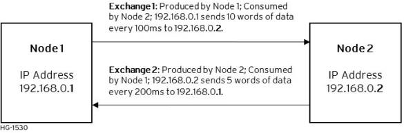
EGD Example 1 - Configuration of Node 1
To configure Node 1 for EGD Example 1, as shown above, perform the following six steps:
Step 1: To configure EGD Exchanges, open the Ethernet Global Data Configuration dialog in EGD Configuration .
In this example Node 1 will have a Static IP address (refer to OCS IP Address Table), and the %R1, %R2, and %R3 registers will be used to report the Ethernet Module’s status, firmware version, and IP address.
Note: Since an IP Address is 32-bits long, Node 1’s IP Address (192.168.0.1) will actually be written into %R3 and %R4.
Ethernet Module Configuration - Node 1

Step 2: Click on LAN1 next to the EGD (Ethernet Global Data) checkbox to open the Ethernet Global Data dialog. Click on Add Exch in the Produced Exchanges dialog.
Creating Produced Exchange – Node 1
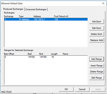
Step 3: Click on Add Range button, in the EGD Configuration dialog, to define a Data Block for Produced Exchange 1. Then fill in the parameters as shown below. Then click OK.
In this example, Node 1 will use Exchange 1 to transmit 10 words of data taken from %R100 through %R109.
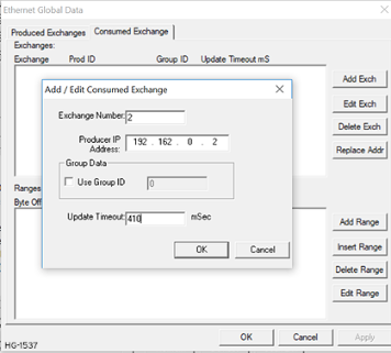
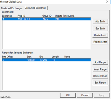
Step 4: To configure Exchange 2 as Consumed Exchange for Node 1, select the Consumed Exchanges tab in the Ethernet Global Data dialog. Click on the Add Exch button to create a Consumed Exchange. Then fill in the parameters as shown.
Note: This is a unicast. Node 1 will be the only Consumer to receive Exchange 2 from Node 2 and will NOT be a member of a Group of Consumers. Also, the Update Timeout is set to 410ms, which means Node 1 will expect to receive Exchange 2 from Node 2 at least every 410ms. [This is twice the time, plus 10ms.]
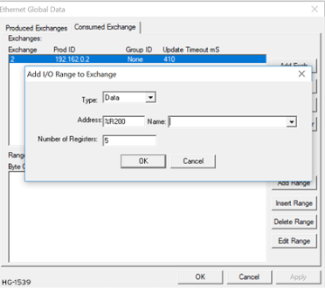
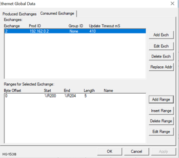
Step 5: Click on the Add Range button in the EGD Configuration dialog to define a Data Block for Consumed Exchange 2. Then fill in the parameters as shown below and click OK. In this example, Node 1 will use Exchange 2 to receive 5 data words in %R200 through %R204.
At this point, the Consumed Exchanges tab in the EGD Configuration dialog should be as shown
Step 6: Node 1 configuration is now complete. Click OK, save the program using an appropriate filename, such as EGD Node 1.csp, and then continue with [Node 2 Configuration].
Return to the Top: Ethernet Global Data Protocol (EGD)
EGD Example 1 - Configuration of Node 2
To configure Node 2 for EGD Example 1, perform the following steps:
Step 1: On the main Cscape screen, select New on the File menu to start a new user program. To configure EGD Exchanges, open the Ethernet Global Data Configuration dialog as described in EGD Configuration . In this example, Node 2 will have a Static IP Address, and the %R1, %R2, and %R3 registers will be used to report the Ethernet Module’s status, firmware version, and IP Address.
Note: Since an IP address is 32-bits long, Node 2’s IP Address (192.168.0.2) will actually be written into %R3 and %R4. Node 2 will transmit Exchange 2 to a specific Consumer (Node 1) because this is a unicast communication, instead of to a group of Consumer (multicast). The Production Period is set to 200, which will cause Node 2 to transmit Exchange 2 every 200ms.
Step 3: Click on the Add Range button in the EGD Configuration dialog to define a Data Block for Produced Exchange 2. Then fill in the parameters as shown below and click OK. In this example, Node 2 will use Exchange 2 to transmit 5 words of data taken from %R100 through %R104.
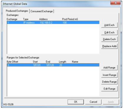
At this point, the Produced Exchanges tab in the EGD Configuration dialog should be as shown in the figure below.
Step 4: Now that Exchange 2 has been configured as a Produced Exchange for Node 2, it is time to configure Exchange 1 as a Consumed Exchange for Node 2. To do this, first select the Consumed Exchanges tab and click on the Add Exch button to create a Consumed Exchange.
Then fill in the parameters, as shown below and click OK. In this example, Node 2 will be the ONLY consumer to receive Exchange 1 from Node 1 and will NOT be a member of a Group of Consumers. Also, the Update Timeout is set to 210, which means that Node 2 will expect to receive Exchange 1 from Node 1 at least every 210ms.
Note: This is twice the time, plus 10ms that Node 1 was configured to transmit Exchange 1, recommended in EGD Terminology Table.

Step 5: Click on the Add Range button, in the EGD Configuration dialog to define a Data Block for Consumed Exchange 1. Then fill in the parameters as shown below and click OK. In this example, Node 2 will use Exchange 1 to receive 10 data words from %R200 through %R209.
Click OK so that dialog matches the one below.
Step 6: Node 2 configuration is now complete. Click OK and save the user program using an appropriate filename, such as EGD Node 2.csp, and then start EGD communication between Node 1 and Node 2.
Return to the Top: Ethernet Global Data Protocol (EGD)
EGD Example 1 - Starting EGD Communication Between Node 1 & Node 2
Now that both Node 1 and Node 2 have been configured for Example 1, start them communicating following these steps:
Step 1: Open the saved Node 1 user program (EGD Node 1.csp) and download it to Node 1.
Step 2: Open the saved Node 2 user program (EGD Node 2.csp) and download it to Node 2.
Step 3: Connect both Node 1 and Node 2 to an Ethernet network and put them both in RUN mode.
At this point, Node 1 and Node 2 should be exchanging EGD data as follows:
-
Every 100ms, Node 1 will read its %R100 through %R109 registers and send them via Exchange 1 to be received by Node 2’s %R200 through %R209 registers.
-
Every 100ms, Node 2 will read its %R100 through %R104 registers and send them via Exchange 2 to be received by Node 1 into Node 1’s %R200 through %R204 registers.
Return to the Top: Ethernet Global Data Protocol (EGD)
Example 2 - Multicast Exchange
EGD Example - Configuring Node 1
The following are the production and consumption range details:
| EGD Example Specifications | |||||
|---|---|---|---|---|---|
| Node 1 – Production Node | |||||
| Exchange #1: Production Details | Exchange #1: Produced Range Details | ||||
| Byte Offset | Start | Length | |||
| Exchange Number | #1 | 0 | %R1001 | 50 | |
| Produced to | Group 1 | 100 | %R1501 | 25 | |
| Production Period | 100ms | 150 | %R1601 | 25 | |
| Node 2 - Consumption Node | |||||
| Exchange Number | #1 | Type | Byte Offset | Start | Length |
| Producer IP | 192.168.0.1 | Data | 0 | %R1 | 50 |
| Group Data ID | 1 | Data | 100 | %R101 | 25 |
| Update Timeout | 210ms | Status | n/a | %R1001 | n/a |
| Node 3 - Consumption Node | |||||
| Exchange Number | #1 | Type | Byte Offset | Start | Length |
| Producer IP | 192.168.0.1 | Data | 0 | %R1 | 50 |
| Group Data ID | 1 | Data | 100 | %R101 | 25 |
| Update Timeout | 210ms | Status | n/a | %R1001 | n/a |
Multicast Configuration Node 1
To configure Node 1 for the EGD Example, perform the following steps:
Step 1: On the main Cscape screen, select the Cscape Icon to start new user program. Then open the OCS configuration dialog by selecting the following in Cscape: Home > Controller > Hardware Configuration, then select Device and Model number. Select EGD checkbox > Configure Selected Protocol. Refer to image below.
Step 2: Once the Configure Selected Protocol button is selected, the Ethernet Global Data dialog is displayed. Two options are available: Produced Exchanges and Consumed Exchanges.
Step 3: Select Add Exch to create a produced exchange, and then select Group ID and add appropriate group number. Click OK.
Note: To create Multicast communication, use Group ID and not IP Address.
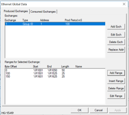
Step 4: The Produced Exchange has been created. Select Exchange 1, then click on the Add Range button to define a Data Block for Produced Exchange 1. Then fill in the parameters and click OK.
Continue adding the rest of the produced range details.
| Exchange #1: Produced Range Details | ||
|---|---|---|
| Byte Offset | Start | Length |
| 0 | %R1001 | 50 |
| 100 | %R1501 | 25 |
| 150 | %R1601 | 25 |
At this point, the Produced Exchanges tab in the EGD Configuration dialog should be as shown in the figure below.
Step 6: Node 1 configuration is now complete. Click OK, save the program using an appropriate filename such as EX_2 Node 1.csp, and then continue with Node 2 configuration.
Note: This is a multicast. Node 1 will produce exchanges to GROUP 1 which in turn will send exchanges to all nodes that are assigned to Group 1.
Return to the Top: Ethernet Global Data Protocol (EGD)
Multicast EGD Example - Configuring Node 2
Step 1: On the main Cscape screen, select the Cscape Icon to start new user program. Then open the OCS configuration dialog by selecting the following in Cscape: Home >Controller > Hardware Configuration, then select Device and Model number. Select EGD checkbox > Configure Selected Protocol. Refer to Multicast Configuration Node 1.
Step 2: Once Exchange 1 has been configured as a Produced Exchange for Node 1, configure Exchange 1 as a Consumed Exchange for Node 2. To do this, first select the Consumed Exchanges tab and click on the Add Exch button to create a Consumed Exchange.
Then fill in the parameters, as shown below, and click OK.
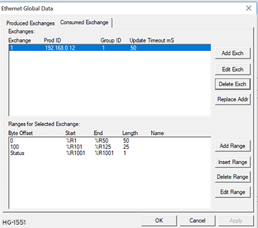
Step 3: Once a Consumed Exchange has been made and highlighted, click on the Add Range button, in the EGD Configuration dialog, to define a Data Block for Consumed Exchange 1. Then fill in the parameters, as shown in below, and click OK.

Continue adding the rest of the produced range details for Node 2.
| Exchange #1: Consumed Range Details | ||
|---|---|---|
| Byte Offset | Start | Length |
| 0 | %R1 | 50 |
| 100 | %R101 | 25 |
| n/a | %R1001 | n/a |
At this point, the Consumed Exchanges tab in the EGD Configuration dialog should be as shown in the figure below.
Step 4: Node 2 configuration is now complete. Click OK, save the program using an appropriate filename such as EX_2 Node 2.csp, and then continue with Node 3 configuration.
Return to the Top: Ethernet Global Data Protocol (EGD)
Multicast EGD Example - Configuring Node 3
Step 1: On the main Cscape screen, select the Cscape Icon to start new user program. Then open the OCS configuration dialog by selecting the following in Cscape: Home >Controller > Hardware Configuration, then select Device and Model number. Select EGD checkbox > Configure Selected Protocol. Refer to Multicast Configuration Node 1.
| Exchange #1: Consumed Range Details | ||
|---|---|---|
| Byte Offset | Start | Length |
| 0 | %R1 | 50 |
| 100 | %R101 | 25 |
| n/a | %R1001 | n/a |
Step 2: Repeat steps from Node 2. Open Then fill in the parameters, as shown below, and click OK.
Then fill in the parameters, as shown below, and click OK.
Step 3: Once a Consumed Exchange has been made and highlighted, click on the Add Range button, in the EGD Configuration dialog, to define a Data Block for Consumed Exchange 1. Then fill in the parameters, as shown in below, and click OK.
Step 4: Node 1 configuration is now complete. Click OK, save the program using an appropriate filename such as EX_2 Node 2.csp, and then continue with Node 3 configuration.
EGD Example 2 - Starting Multicast EGD Communication
-
Open the saved Node 1 user program (Node 1.csp) and download it to Node 1.
-
Open the saved Node 2 user program (Node 2.csp) and download it to Node 2.
-
Open the saved Node 3 user program (Node 3.csp) and download it to Node 3.
Connect both Node 1, Node 2, and Node 3 to an Ethernet network and put them both in RUN mode.
Return to the Top: Ethernet Global Data Protocol (EGD)