Logic Modules in IEC 
See also: IEC 61131 Language Editor Programming
See also: Enhanced IEC 61131 Guide
Topic Menu
IEC Languages
There are five IEC languages available:
Recommended for backwards-compatibility of existing code only: While all products support the IEC languages, some products optionally allow the use of Enhanced IEC functionality as a licensed feature. The use of this editor is automatic if the licensing is in place and the option to allow it is selected. See also: Enhanced IEC 61131 Guide
Logic Modules for IEC
Logic Modules can be accessed two ways:
-
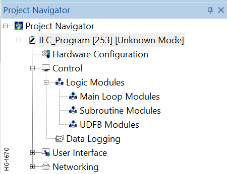
Option 1: Through the Project Navigator: Ensure the Project Navigator is open:Home > View > Project Navigator
-
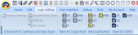
Option Two: Through the Menu Ribbon in the Logic Editing tab.
Logic Modules - To better organize the application programs, the logic can be divided into multiple modules. These modules can be main loop or subroutines modules as per the requirement of the application.
Main Loop Modules - These blocks are executed once on each scan of the PLC in the order in which they are defined.
Subroutine Loop Modules - These blocks are callable from all the other block types. Subroutine modules can have private and local variables which will be allocated single storage. Hence calling the block from two different places will operate on the same private and local variables.
UDFB Modules - These blocks are callable from all the other block types. UDFB modules can have private and local variables which will be allocated with unique storage. Hence calling the blocks from two different places will operate on different private and local variables
Note: UDFB Modules are only available in Variable-Based Advanced Ladder and in IEC editor programs.
Datalogging - The Data Log utility is designed to allow any controller with a Removable Media port to periodically log register values to removable media (microSD or CompactFlash). The register data is stored in .CSV (comma separated value) format, which is compatible with 3rd party PC applications, such as Microsoft Excel. See also: Datalogging
Return to the Top: Logic Modules in IEC
Creating a New Logic Block 

|
Structured Text Logic Block |
")
|
Ladder Diagram (LD) Logic Block |
")
|
Instruction List Logic Block |
")
|
Function Block Diagram (FBD) Logic Block |

|
Sequential Function Chart (SFC) Logic Block |
To select a new Main Loop Modules, open the Control Node in the Project Navigator > Main Loop Modules [Right-Click] > New Logic Block > IEC language. (See IEC Languages)
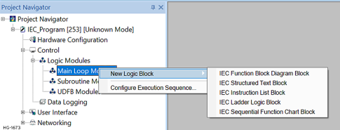
These blocks are executed once on each scan of the PLC in the order in which they are defined. The user can configure the compilation sequence of multiple blocks in main loop modules area of an IEC Program by accessing the IEC Modules Compilation Sequence Configuration dialog. See: Configure Execution Sequence . The programming language for main loop modules can be selected using right-click on the Main Loop Modules node under Logic Modules from the program node of the Project Navigator.
The programming language can also be selected by using the Logic Editing > IEC 61131 > IEC Function Block Diagram Block.
Note: Selecting a different icon in this section selects different IEC programming language.

Note: SFC programs may only be created as Logic Blocks.
Import Logic Module
To import a Logic Module, right-click on the Logic Modules Node and select Import Logic Module.
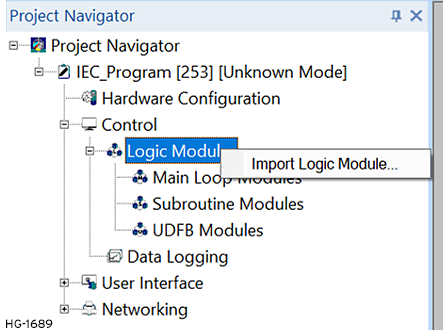
This will open a window to allow the user to select desired file.
Return to the Top: Logic Modules in IEC
Logic Block Right-Click Options
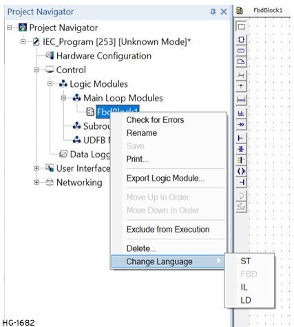
Check for Errors: Manually check a program for errors.
Rename: Allows Block to be renamed.
Save: Saves the Block
Print: Prints the Block
Export Logic Module: Exports the Block
Move Up in Order: Moves the selected module one step up the execution order.
Move Down in Order: Moves the selected module one step down the execution order.
Exclude from Compilation: Excludes the selected module from being compiled / executed during runtime.
Delete: Any Block that is not required can also be deleted from the Logic Module by right-clicking on the block and select Delete.
Change Language: Change to another IEC Language.
Note: The same options are available for a right-click on the Subroutine Module and the UDFB Module
Configure Execution Sequence
Configure Compilation Sequence can be accessed either by right-clicking on the Main Loop Modules or right-clicking on individual modules:
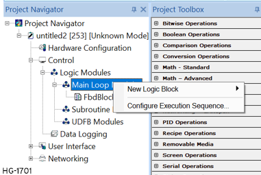
Selecting Configure Execution Sequence opens the following screen:
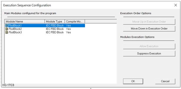
The user can change the compilation order of the programs by using either Move Up in compile order or Move Down in Compile order buttons.
-
Move Up in Compile Order: Moves the selected program one step up the compilation order.
-
Move Down in Compile Order: Moves the selected program one step down the compilation order.
Note: SFC block compilation order cannot be changed, and they always remain last in the compilation order. But the compilation order of multiple SFC blocks can be changed within themselves.
The user can also include/exclude a logic module in the main loop modules section from compilation sequence by using Allow Execution/Suppress Execution options.
This option can be selected either through IEC Modules Compilation Sequence Configuration window, see above, or by right-clicking on any modules. See below:
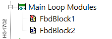
Any Module which is excluded from Compilation will have a RED mark indicated on the module as shown below:
Return to the Top: Logic Modules in IEC
Subroutine Modules 


|
Structured Text Subroutine Logic Block |

|
Ladder Diagram (LD) Subroutine Logic Block |

|
Instruction List Subroutine Logic Block |

|
Function Block Diagram (FBD) Subroutine Logic Block |
These blocks are callable from all the other block types. Subroutine modules can have private and local variables which will be allocated single storage. Hence calling the block from two different places will operate on the same private and local variables.
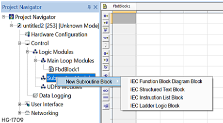
Subroutine Modules can be created through the Logic Editing Menu or the Project Navigator.

When a subroutine module is created, the same gets listed in the project toolbox under group 'Project'. These modules can then be dragged and dropped as other function blocks.
Subroutine Right-Click Options
After creating a new Subroutine Module, the right-click options are the same as the Main Loop Module, see Logic Block Right-Click Options
Return to the Top: Logic Modules in IEC
UDFB Modules 


|
Structured Text UDFB Logic Block |

|
Ladder Diagram (LD) UDFB Logic Block |

|
Instruction List UDFB Logic Block |

|
Function Block Diagram (FBD) UDFB Logic Block |
These blocks are callable from all the other block types. UDFB modules can have private and local variables which will be allocated with unique storage. Hence calling the blocks from two different places will operate on different private and local variables.
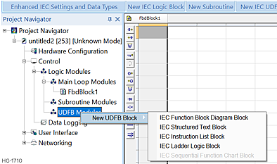
UDFB Modules can be created through the Logic Editing Menu or the Project Navigator.

UDFB Right-Click Options
When a UDFB module is created, the same gets listed in the project toolbox under group 'Project'. These modules can then be dragged and dropped as other function blocks.
After creating a new UDFB Module, the right-click options are the same as the Main Loop Module, see Logic Block Right-Click Options
Return to the Top: Logic Modules in IEC
Debugging UDFB Logic Modules
For this to be operational, the user needs to select "Support Array of structures" in Editor options.
For Example: In the below UDFB block, values 10 and 20 are given as inputs, in order to debug this block, right-click on the block and select "Open UDFB".
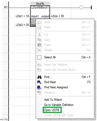
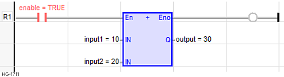
This opens the UDFB module as shown below for debugging:
Return to the Top: Logic Modules in IEC