Sequential Function Chart (SFC) 
See also: IEC 61131 Language Editor Programming
See also: Project Toolbox for IEC
Topic Menu

|
Getting Started with IEC 6-1131 Sequential Function Block in Cscape |
SFC Overview
The SFC language is a state diagram. Graphical steps are used to represent stable states, and transitions describe the conditions and events that lead to a change of state. Using SFC highly simplifies the programming of sequential operations as it saves a lot of variables and tests just for maintaining the program context.
NOTE: The user should not use SFC as a decision diagram. Using a step as a point of decision and transitions as conditions in an algorithm should never appear in a SFC chart. Using SFC as a decision language leads to poor performance and complicated charts. ST should be preferred when programming a decision algorithm that has no sense in terms of "program state".
SFC Toolbar
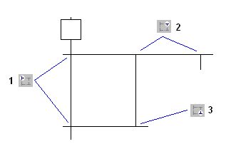
The vertical toolbar on the left side of the editor contains buttons for inserting items in the chart. Items are always inserted before the selected item. The chart is automatically re-arranged when a new item is inserted.

|
Initial Step[I] - Insert an initial step |

|
Step[S] - Insert a Step |
|
|
Transition[T] - Insert a transition |
|
|
Set Timer on transition - Set a timer to a transition |

|
Jump[J] - Insert a jump to a step |

|
Divergence[X] - Insert the main (left side) corner of a divergence or convergence |

|
Divergence[D] - Insert a divergence corner |

|
Convergence[C] - Insert a convergence corner |

|
Macro[M] - Insert a macro-step |

|
Macro Body[B] - Insert the body of a macro-step |

|
Swap Item Style(Space) - Swap between possible overview:
|

|
Step Selection - Switch between Initial Step or a Step. This is available for Steps only |

|
Renumber - Assigned number in order. |

|
Edit Reference - New Reference can be assigned |
Use the following keyboard commands when an item is selected:
ENTER: Edit the level 2 of a step or transition
Ctrl+ENTER: Change the number of a step, transition or jump
SPACE BAR on the main corner (on the left) of a divergence or convergence to set double/single horizontal line style.
Return to the Top: Sequential Function Chart (SFC)
Initial Steps in SFC 
Initial steps represent the initial situation of the chart when the program is started. There must be at least one initial step in each SFC chart. An initial step is marked with a double line as shown below:
SFC Steps 
A step represents a stable state. It is drawn as a square box in the SFC chart. Each must step of a program is identified by a unique number. At run time, a step can be either active or inactive according to the state of the program. NOTE: To change the number of a step, transition or jump, select it and hit Ctrl+ENTER keys. All actions linked to the steps are executed according to the activity of the step.
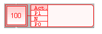
Inactive Step
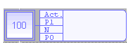
Active Step
In conditions and actions of the SFC program, the user can test the step activity by specifying its name ("GS" plus the step number) followed by ".X".
For example: GS100.Xis TRUE if step 100 is active (expression has the BOOL![]() Boolean- [Data Type BOOL] - A single bit, binary value, or register/variable. Boolean points have only two possible values, 'TRUE' or 'FALSE'. data type)
Boolean- [Data Type BOOL] - A single bit, binary value, or register/variable. Boolean points have only two possible values, 'TRUE' or 'FALSE'. data type)
The user can also test the activity time of a step, by specifying the step name followed by ".T". It is the time elapsed since the activation of the step. When the step is deactivated, this time remains unchanged. It will be reset to 0 on the next step activation.
For example: GS100.T is the time elapsed since step 100 was activated (expression has the TIME data type)
Return to the Top: Sequential Function Chart (SFC)
SFC Transitions 
Transitions represent a condition that changes the program activity from a step to another. NOTE: To change the number of a step, transition or jump, select it and hit Ctrl+ENTER keys.
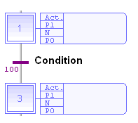
The transition is marked by a small horizontal line that crosses a link drawn between the two steps:
-
Each transition is identified by a unique number in the SFC program.
-
Each transition must be completed with a Boolean
 Boolean- [Data Type BOOL] - A single bit, binary value, or register/variable. Boolean points have only two possible values, 'TRUE' or 'FALSE'. condition that indicates if the transition can be crossed. The condition is a BOOL expression.
 -
In order to simplify the chart and reduce the number of drawn links, the user can specify the activity flag of a step (GSnnn.X) in the condition of the transition.
Transitions define the dynamic behavior of the SFC chart, according to the following rules:
-
A transition in crossed if:
-
its condition is TRUE
-
and if all steps linked to the top of the transition (before) are active
-
-
When a transition is crossed:
-
all steps linked to the top of the transition (before) are de-activated
-
all steps linked to the bottom of the transition (after) are activated
-
Condition of an SFC Transition
Each SFC transitions must have a Boolean condition that indicates if the transition can be crossed. The condition is a Boolean expression that can be programmed either in ST or LD language.
![]()
The following conditions can be attributed to a Transition:
![]() Transition[T] - Insert a transition
Transition[T] - Insert a transition
![]() Set Timer on transition - Set a timer to a transition
Set Timer on transition - Set a timer to a transition
-
A Timed Transition will execute the next Step after the time has elapsed.
-
In ST language, enter a Boolean expression. In can be a complex expression including function calls and parenthesis. For example:
-
bForce AND (bAlarm OR min (iLevel, 1) <> 1)
-
In LD language, the condition is represented by a single rung. The coil at the end of the rung represents the transition and should have no symbol attached. For example:
![]()
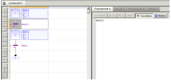
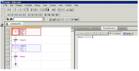
Entering the Condition of a Transition in SFC
The condition and notes attached to a transition (level 2) are entered in a separate window. To open the level 2 editing window of a step or transition, double click on its symbol in the chart, or select it and hit ENTER. See also: Condition of an SFC Transition and Entering Notes for Steps and Transitions in SFC
The level 2 editing window proposes 2 views for entering different types of level 2 information:
-
condition programmed in ST/IL text or LD
-
text notes
Use the tab buttons in the level 2 editing window for selecting a view:
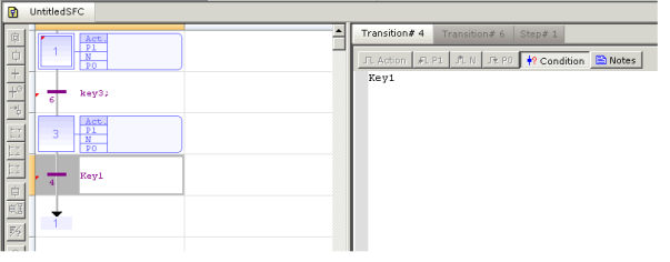
The languages that can be used to edit the conditions for a step or transition can be modified if that condition supports multiple languages. The description Condition will be available only for Transitions. The descriptions are displayed in the box next to each step and transition. Transition Condition: ST/LD Languages are allowed
The default setting of language used to edit conditions of a step or transition is set to ST Language. In order to change the type of language for a step, the user can select it from the Edit menu. NOTE: The language can be changed for a condition only if the condition contents are empty. When editing the condition , use the "Edit / Set Language" menu command to select the programming language. This command is not available if the condition is not empty. FBD cannot be used to program a condition.
Return to the Top: Sequential Function Chart (SFC)
Jump to an SFC step 
Jump symbols can be used in SFC charts to represent a link from a transition to a step without actually drawing it. The jump is represented by an arrow identified with the number of the target step. NOTE: To change the number of a step, transition or jump, select it and hit Ctrl+ENTER keys.
The user cannot insert a jump to a transition as it may lead to a non explicit convergence of parallel branches (several steps leading to the same transition) and generally leads to mistakes due to a bad understanding of the chart.
SFC Divergences
It is possible to link a step to several transitions and thus create a divergence. The divergence is represented by a horizontal line. Transitions after the divergence represent several possible changes in the situation of the program. All conditions are considered as exclusive, according to a "left to right" priority order. It means that a transition is considered as FALSE if at least one of the transitions connected to the same divergence on its left side is TRUE.
Below is an example:
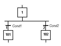
Transition 1 is crossed if: Step 1 is active and Cond1 is TRUE
Transition 2 is crossed if: Step 1 is active and Cond2 is TRUE and Cond1 is FALSE
Drawing SFC Divergences
When using the SFC editor, the user just needs to place items in the grid. The editor calculates and draws lines automatically to link steps, transitions and jumps placed in the chart. The same method is used for drawing divergences: the user just needs to place the "corners" that identifies divergences, convergences and branches. The editor takes care of drawing vertical and horizontal lines.
Use the following buttons in the SFC toolbar:
 Divergence[X] - Insert the main (left side) corner of a divergence or convergence
Divergence[D] - Insert a divergence corner
Convergence[C] - Insert a convergence corner
IMPORTANT NOTE: Divergences are always drawn from the left to the right. The first branch, on the left, contains the "corners" that identify the divergence. It must be aligned with the preceding step or transition:
How to proceed:
-
Insert the main corner (on the left side branch) of the divergence and the convergence
-
Insert corners at the top of each branch (divergence)
-
Insert corners at the bottom of the branches where a divergence is wished
Simple or double divergence lines: The user can change the drawing of a divergence or convergence horizontal line, for drawing simple or double lines according to SFC definition. To do that, move the selection on the main corner (on the left) and hit the SPACE bar.
Return to the Top: Sequential Function Chart (SFC)
SFC Macro Steps
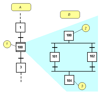
A macro step is a special symbol that represents, within a SFC chart, a part of the chart that begins with a step and ends with a step. The body of the macro-step must be declared in the same program. The body of a macro-step begins with a special "begin" step with no link before, and ends with a special "end" step with no link after. The symbol of the macros step in the main chart has double horizontal lines:
Important Notes:
-
The macro-step symbol and the beginning step must have the same number.
-
The body of the macro-step should have no link with other parts of the main diagram (must be connex).
-
A macro step is not a "sub program". It is just a drawing features that enables the user to make clearer charts. The user should never insert several macro-step symbols referring to the same macro-step body.
Entering SFC Macro-Steps
A Macro Step is a special symbol that represents, within a SFC chart, a part of the chart that begins with a step and ends with a step. The body of the macro-step must be declared in the same program. The body of a macro-step begins with a special "begin" step with no link before, and ends with a special "end" step with no link after. The symbol of the macros step in the main chart has double horizontal lines.
Use the following buttons of the SFC toolbar for entering macro-steps:
Macro[M] - Insert a macro-step
Macro Body[B] - Insert the body of a macro-step
NOTE: The symbol of the macro-step and the beginning step of its body must have the same number. Hit Ctrl+ENTER when a macro-step symbol or a beginning step is selected to change its number.
Return to the Top: Sequential Function Chart (SFC)
Viewing SFC Charts
The chart is entered in a logical grid. All objects are snapped to the grid. At any moment the user can use the commands of the "View" menu for zooming in or out the edited chart. The user also can press the [ + ] and [ - ] keys of the numerical keypad for zooming the diagram in or out.
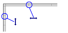
The user also can drag the separation lines in vertical and horizontal rulers to freely resize the cells of the grid:
The SFC editor adjusts the size of the font according to the zoom ratio. When cells are wide enough, a text overview with the contents of the step or transition (level 2). The last button of the toolbar enables the user to switch between possible displays:
Swap between possible overviews of level 2 in the level 1 chart:
-
display code of actions and conditions
-
display notes attached to steps and transitions
Return to the Top: Sequential Function Chart (SFC)
Moving and Copying SFC Charts
The SFC editor fully supports drag and drop for moving or copying items. To move items, select them and simply drag them to the desired position. To copy items, the user may do the same, and just press the CONTROL key while dragging. It is also possible to drag pieces of charts from a program to another if both are open and visible on the screen. While dragging items the user can press ESCAPE to cancel the operation. Alternatively, the user can use classical Copy / Cut / Paste commands from the Edit menu. Paste is performed at the current position.
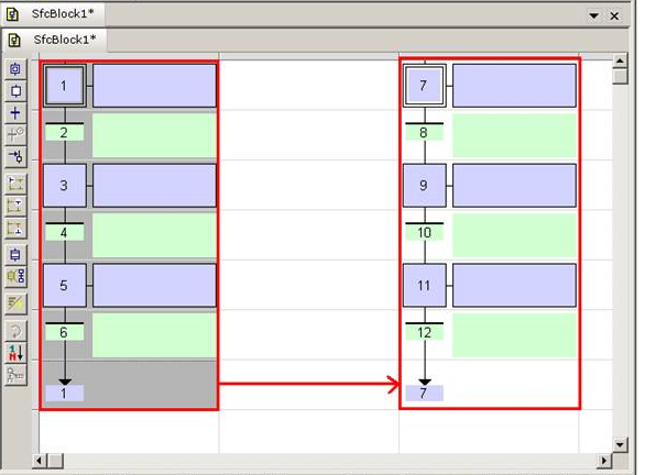
Steps to be followed to perform Drag/Drop Operation in IEC Program’s SFC Editor:
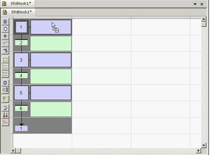
Step 1: Open the SFC Logic Module Editor whose logic has to be moved/copied.
Step 2: Select the logic section to be moved/copied.
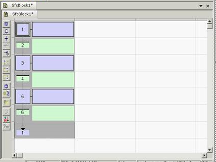
Step 3: Bring the mouse cursor on the selection area and hold left mouse button in pressed state for couple of seconds until the selected area’s background color changes and the cursor’s shape changes.
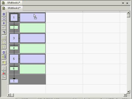
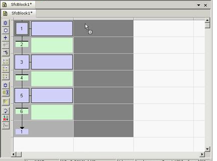
Step 4: With the mouse’s left mouse button in pressed state move the mouse to move the selection to desired area.
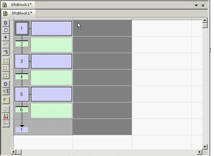
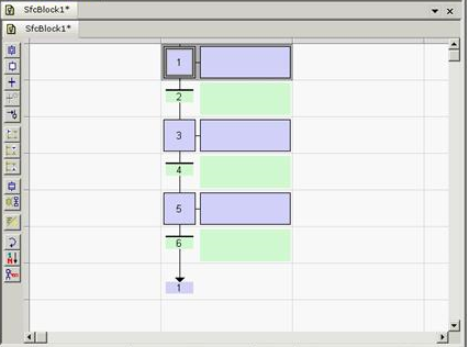
After releasing the mouse, the copy of the selected area must be placed in the desired location:
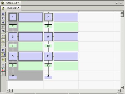
If the selection is to be copied, the hold the CONTROL Key in pressed state while moving and releasing the left mouse button.
With the left mouse button in pressed state move the mouse to move the selection to desired area.
After releasing the mouse, the copy of the selected area must be placed in the desired location:
Steps to be followed to while copying SFC Module’s Logic section that has Jump Block included in the selection:
Improper Selection: Selected area does not include Step#1 which the Jump block is referring to. As a result, after Copy/Paste, Jump block's Jump value does not get updated.
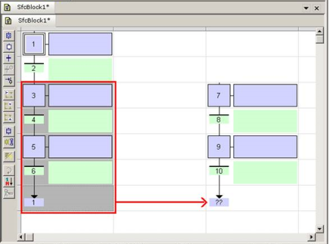
Proper Selection: Selected area includes the block to which the Jump block is referring to. As a result, when a Copy/Paste operation is done, the Jump value is also updated.
Return to the Top: Sequential Function Chart (SFC)
SFC Parallel Branches
Parallel branches are used in SFC charts to represent parallel operations. Parallel branches occur when more than several steps are connected after the same transition.
Parallel branches are drawn as double horizontal lines:
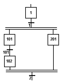
-
When the transition before the divergence (1 on this example) is crossed, all steps beginning the parallel branches (101 and 201 here) are activated.
-
Sequencing of parallel branches may take different timing according to each branch execution.
-
The transition after the convergence (2 on this example) is crossed when all the steps connected before the convergence line (last step of each branch) are active. The transition indicates a synchronization of all parallel branches.
-
If needed, a branch may be finished with an "empty" step (with no action). It represents the state where the branch "waits" for the other ones to be completed.
The user must take care of the following rules when drawing parallel lines in order to avoid dead locks in the execution of the program:
-
All branches must be connected to the divergence and the convergence.
-
An element of a branch must not be connected to an element outside the divergence.
Return to the Top: Sequential Function Chart (SFC)
Numbering Steps and Transitions in SFC
Each step or transition is identified by a number. A jump to a step is also identified by the number of the destination step. The SFC editor allocates a new number to each step or transition inserted in the chart. To change the number of a step, transition or jump, select it and hit Ctrl+ENTER keys. It is not possible to change the number of a step or a transition if its level 2 is currently open for editing. The number is used for identifying the step or transition in the level 2 editing window. In compiler reports, a step is identified by its number prefixed by "GS". A transition is identified by its number prefixed by "GT".
Actions of an SFC Step
Each step has a list of action blocks, that are instructions to be executed according to the activity of the step. Actions can be simple Boolean or SFC actions, that consists in assigning a Boolean variable or control a child SFC program using the step activity, or action blocks entered using another language (FBD, LD, ST or IL).
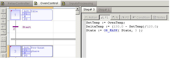
Example of an action in ST Language:
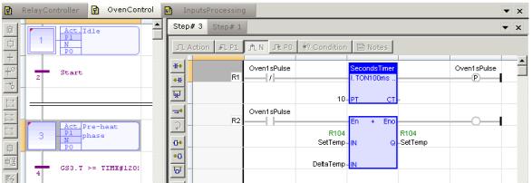
Example of an action in LD Language:
Simple Boolean Boolean- [Data Type BOOL] - A single bit, binary value, or register/variable. Boolean points have only two possible values, 'TRUE' or 'FALSE'. Actions
Below are the possible syntax the user can use within an SFC step to perform a simple Boolean action:
-
BoolVar (N); - Forces the variable "BoolVar" to TRUE when the step is activated, and to FALSE when the step is de-activated.
-
BoolVar (S); - Sets the variable "BoolVar" to TRUE when step is activated
-
BoolVar (R); -Sets the variable "BoolVar" to FALSE when step is activated
-
/ BoolVar; - Forces the variable "BoolVar" to FALSE when the step is activated, and to TRUE when the step is de-activated.
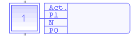
Programmed Action Blocks
Programs in other languages (FBD, LD, ST or IL) can be entered to describe an SFC step action. There are three main types of programmed action blocks, that correspond to the following identifiers:
-
P1 - Executed only once when the step becomes active
-
N - Executed on each cycle while the step is active
-
P0 - Executed only once when the step becomes inactive
Cscape provides the user templates for entering P1, N and P0 action blocks in either ST, LD or FBD language. Alternatively, the user can insert action blocks programmed in ST language directly in the list of simple actions, using the following syntax:
ACTION (qualifier) :
statements...
END_ACTION;
Where qualifier is "P1", "N" or "P0".
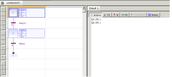
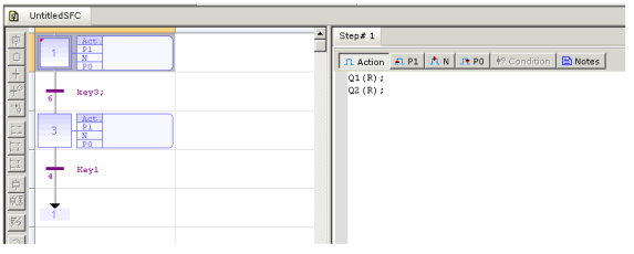
Entering Actions of a Step
Actions and Notes attached to a step (level 2) are entered in a separate window. To open the level 2 editing window of a step or transition, double click on its symbol in the chart, or select it and hit ENTER. See also: Actions of an SFC Step and Entering Notes for Steps and Transitions in SFC
The level 2 editing window proposes 4 views for entering different types of level 2 information:
-
simple actions entered as text
-
P1 actions than can be programmed in ST/IL text, LD or FBD
-
N actions than can be programmed in ST/IL text, LD or FBD
-
P0 actions than can be programmed in ST/IL text, LD or FBD
-
text notes
Use the tab buttons in the level 2 editing window for selecting a view:
The condition for Steps and Transitions of IEC SFC Editor can be made in the embedded conditions editor tab.
The editor for preferred condition of a step can be accessed by clicking the appropriate toolbar button.
The condition Action – as described in Action tab, P1 – Rising Edge, N – Every cycle, P0 – Falling Edge will be available for Steps. These conditions will be executed when the Step is activated.
The descriptions are displayed in the box next to each step.
-
Action Condition – Only ST Language is Allowed.
-
P1 Condition: ST/FBD/LD Languages are allowed.
-
N Condition: ST/FBD/LD Languages are allowed.
-
P0 Condition: ST/FBD/LD Languages are allowed.
The default setting of language used to edit conditions of a step or transition is set to ST Language. In order to change the type of language for a step, the user can select it from the Edit menu. NOTE: The language can be changed for a condition only if the condition contents are empty.
When editing P1, N or P0 actions, use the "Edit / Set Language" menu command to select the programming language. This command is not available if the action block is not empty. The first view ("Action") contains all simple actions to control a Boolean variable. However, it is possible to directly enter action blocks programmed in ST together with other actions in this view.
Use the following syntax for entering ST action blocks in the first pane:
ACTION (qualifier) :
statements...
END_ACTION;
Where qualifier is "P1", "N" or "P0"
Return to the Top: Sequential Function Chart (SFC)
Entering Notes for Steps and Transitions in SFC
The SFC editor supports the definition of text notes for each step and transition. The notes are entered in the level 2 editing window of steps and transitions. Refer to the following topics for further information about the level 2 editing window:
-
Entering Level 2 for steps, See Actions of an SFC Step
-
Entering Level 2 for transitions, See Condition of an SFC Transition
 Notes can be displayed in the chart. The last button of the toolbar enables the user to switch between possible displays:
Swap between possible overviews of level 2 in the level 1 chart:
-
display code of actions and conditions
-
display notes attached to steps and transitions
Notes have no meaning for the execution of the chart. Entering notes for steps and transitions enables the user to enhance the auto-documentation of programs. It also provides an easy way to write and exchange specifications of an SFC program before actions and conditions are programmed.
Return to the Top: Sequential Function Chart (SFC)
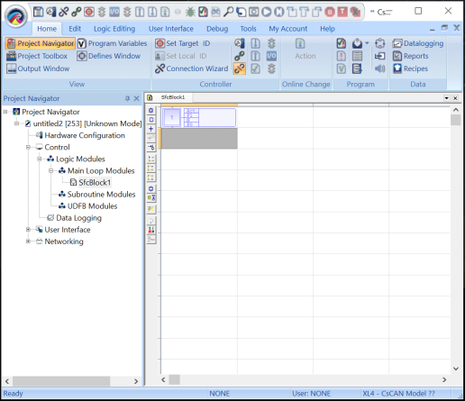
Viewing SFC Logic and Editor
Access to SFC Logic and Secondary Editors Simultaneously:
The user can now view and edit the logic associated with multiple step/transition blocks of an SFC Logic Module simultaneously. The secondary editor can be opened in either of the following ways:
-
Double clicking on a step/transition or select it and hit ENTER to open its associated editor
-
Using right-click options to open secondary editor
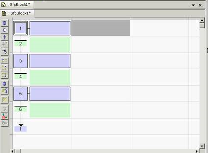
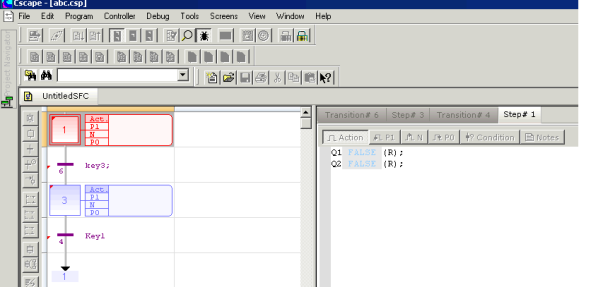
Once selected for viewing/editing, the step or transition will be opened in an editor window indicating the respective step/ transition name as a tab:
Opening multiple Step/Transition Editors
Multiple steps/transitions can be opened for viewing & editing in non-debug mode. Once opened the open steps/transitions are indicated with a lock status (red indication on the left hand corner of the step/transition).
When secondary editors set for one or more Step/Transition block has been opened, the main SFC Logic Editor will set to read-only mode. In this mode, the normal operations will be disabled along with the sticky toolbar. In this mode, the user can only:
-
Double-click on step/transition block or select it and hit ENTER to access its secondary editors’ view set.
-
Right-click on step/transition block to access the context menu.
Once all secondary editors’ sets have been closed, the SFC Logic block will be set to normal mode. NOTE: Closing of the respective step/transition removes the lock indication.
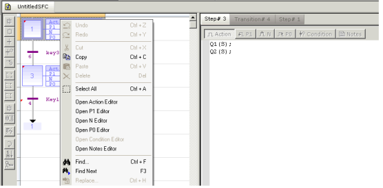
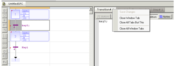
Right-Click Options on Tab Name of Secondary Editors
The following right-click options on tab name of secondary editors to save & close of Steps/Transitions are available to the user.
Right-click option on secondary editor tab include:
-
Save Changes - Saves any changes.
-
Close window tab - closes the selected tab
-
Close all but this - closes all the opened tabs but the selected one
-
Close all Window tab - closes all the opened tab.
NOTE: Save option is available only if changes have been made in the selected Step/Transition
Return to the Top: Sequential Function Chart (SFC)
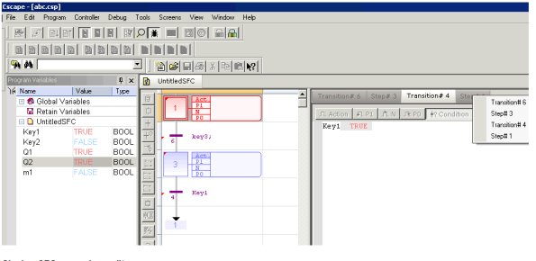
Debugging Step/Transition Logic in SFC
The user can debug the main SFC Logic as well as the secondary logic and view them simultaneously. The active step/transition in run is indicated with red color. In debug mode SFC logics & secondary editor are not allowed for editing. Multiple steps/transitions can be opened for viewing during debug mode.
Selection of Opened Steps/ Transitions
Multiple steps/ transitions opened can be selected from the drop down list and navigated in both debug & non-debug mode:
Closing SFC Secondary Editors
The close icon on the secondary editor can be used to close individual steps/transitions. The tab right-click options listed above can also be used for multiple tab closures.
Return to the Top: Sequential Function Chart (SFC)
SFC Execution at Run Time
SFC programs are executed sequentially within a target cycle, according to the order defined when entering programs in the hierarchy tree. Within a chart, all valid transitions are evaluated first, and then actions of active steps are performed. The chart is evaluated from the left to the right and from the top to the bottom.
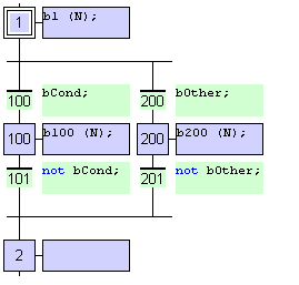
Below is an example:
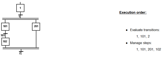
In case of a divergence, all conditions are considered as exclusive, according to a "left to right" priority order. It means that a transition is considered as FALSE if at least one of the transitions connected to the same divergence on its left side is TRUE.
The initial steps define the initial status of the program when it is started. All top level (main) programs are started when the application starts.
The evaluation of transitions leads to changes of active steps, according to the following rules:
-
A transition in crossed if:
-
its condition is TRUE
-
and if all steps linked to the top of the transition (before) are active
-
-
When a transition is crossed:
-
all steps linked to the top of the transition (before) are deactivated
-
all steps linked to the bottom of the transition (after) are activated
-
Important Note: Execution of SFC within the target is sampled according to the target cycles. When a transition is crossed within a cycle, the following steps are activated, and the evaluation of the chart will continue on the next cycle. If several consecutive transitions are TRUE within a branch, only one of them is crossed within one target cycle.
Return to the Top: Sequential Function Chart (SFC)