Function Block Diagram (FBD) ")
See also: IEC 61131 Language Editor Programming
See also: Enhanced IEC 61131 Guide
Topic Menu

|
Getting Started with IEC 6-1131 Function Block Diagram in Cscape |
Common Elements in LD and FBD
Note: LD and FBD are both Graphic Languages.
See also: Ladder Diagram (LD)
See also: IEC Editors and Basic Operations
Note: When a contact or a coil is selected, the user can press the SPACE bar to change its type (normal, negated, pulse...).
FBD Overview
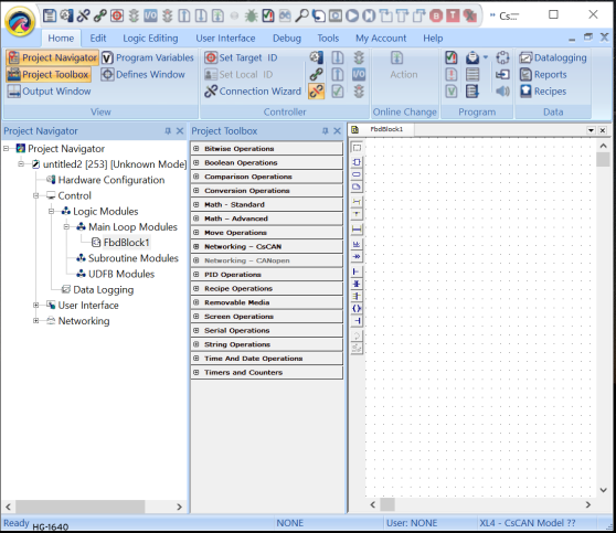
The FBD editor is a powerful graphical tool that enables the users to enter and manages Function Block Diagrams according to the IEC 61131-3 standard. The editor supports advanced graphic features such as drag and drop, object resizing and connection lines routing features, so that the user can rapidly and freely arrange the elements of diagram. It also enables the user to insert in a FBD diagram graphic elements of the LD (Ladder Diagram) language such as contacts and coils.
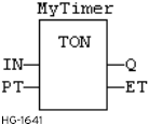
A Function Block Diagram is a data flow between or and operations represented by rectangular blocks. See Function Calls or Function Block Calls in IEC Editors and Basic Operations. The name of the operation or function, or the type of function block is written within the block rectangle. In case of a function block call, the name of the called instance must be written upon the block rectangle, such as in the example below:
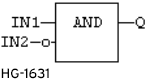
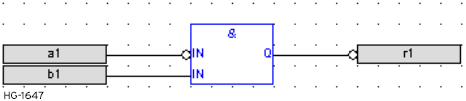
The data flow may represent values of any data type. All connections must be from input and outputs points having the same data type. In case of a Boolean![]() Boolean- [Data Type BOOL] - A single bit, binary value, or register/variable. Boolean points have only two possible values, 'TRUE' or 'FALSE'. connection, the user can use a connection link terminated by a small circle, that indicates a Boolean negation of the data flow. Below is an example:
Boolean- [Data Type BOOL] - A single bit, binary value, or register/variable. Boolean points have only two possible values, 'TRUE' or 'FALSE'. connection, the user can use a connection link terminated by a small circle, that indicates a Boolean negation of the data flow. Below is an example:
(* use of a negated link: Q is IN1 AND NOT IN2 *)
The data flow must be read from the left to the right and from the top to the bottom. It is possible to use and to change the default data flow execution.
Return to the Top: Function Block Diagram (FBD)
FBD Toolbar

|
Element Selection - In this mode, no insertion of any element possible in the diagram. The mouse is used for selecting object and lines, select tag name areas, move or copy objects in the diagram. At any moment the user can press the ESCAPE key to go back to the Selection mode. See Moving or Copying FBD Objects, Resizing FBD Objects, Variable Selection Box |

|
Add Function Block -In this mode, the mouse is used for inserting blocks in the diagram. Click in the diagram and drag the new block to the wished position. The type of block that is inserted is the one currently selected in the list of function blocks. SeeVariable Selection Box or Drawing FBD Connection Lines . |

|
Add Variable -In this mode, the mouse is used for inserting variable tags. Variable tags can then be wired to the input and output pins of the blocks. Click on the diagram and drag the new variable to the wished position. See Variable Selection Box. |

|
Add Comment -In this mode, the mouse is used for inserting comment text areas in the diagram. Comment texts can be entered anywhere. Click in the diagram and drag the text block to the wished position. The text area can then be selected and resized. See FBD Comments |

|
Add Arc - In this mode, the mouse is used to wire input and output pins of the diagram objects. The line must always be drawn in the direction of the data flow: from an output pin to an input pin. See Drawing FBD Connection Lines. |

|
Add Corner -In this mode, the mouse is used for inserting a user defined corner on a line. See FBD Corners. |

|
Add break -In this mode, the mouse is used for inserting a horizontal line that acts as a break in the diagram. Breaks have no meaning for the execution of the program. They just help the understanding of big diagrams, by splitting them in a list of networks. See FBD Network Breaks |

|
Add Label -In this mode, the mouse is used for inserting a label in the diagram. A label is used as a destination for jump symbols. See Variable Selection Box. |

|
Add Jump - In this mode, the mouse is used for inserting jump symbols in the diagram. A jump indicates that the execution must be directed to the corresponding label (having the same name as the jump symbol). Jumps are conditional instructions. They must be linked on their left side to a Boolean data flow. See Variable Selection Box or Drawing FBD Connection Lines. |

|
Add Left Power Rail -In this mode, the mouse is used for inserting a left power rail in the diagram. A left power rail is an element of the LD language, and represents a "TRUE" state that can be used to initiate a data flow. Power rails can then be selected and sized vertically according to the wished network height. See Drawing FBD Connection Lines |

|
Add Direct Contact - In this mode, the mouse is used for inserting in the diagram a contact as in Ladder Diagrams. See Variable Selection Box or Drawing FBD Connection Lines. |

|
Add "OR" Bar -In this mode, the mouse is used for inserting a rail that collects several Boolean data flows for an "OR" operation, in order to insert parallel contacts such as done in Ladder Diagrams. See Drawing FBD Connection Lines or FBD "OR" Vertical Rail |

|
Add Direct Coil -In this mode, the mouse is used for inserting in the diagram a coil as in Ladder Diagrams. It is not mandatory that a coil be connected on its right side. |

|
Add Right Power Rail -In this mode, the mouse is used for inserting a right power rail in the diagram. A right power rail is an element of the LD language, and is commonly used for terminating Boolean data flows. However it is not mandatory to connect coils to power rails. Right power rails have no meaning for the execution of the diagram. See Drawing FBD Connection Lines |

|
Swap Item Style: Swaps visibility between tag & description for a variable. Space bar can also be used for this function. |

|
Show Execution Order: Shows execution order for blocks. |
Return to the Top: Function Block Diagram (FBD)
FBD Variables
All variable symbols and constant expressions are entered in FBD diagrams using small boxes. Press the following button in the FBD toolbar for inserting a variable tag:
 Insert Variable: In this mode, the mouse is used for inserting variable tags. Click in the diagram and drag the new variable to the wished position. Double click on a variable tag to open the Variable Selection Box and either select the symbol of the wished variable or enter a constant expression. Variables tags must then be linked to other objects such as block inputs and outputs using connection lines.
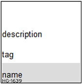
The user can resize a variable box vertically in order to display together with the variable name its tag (explicit link to the registers), its description text. The variable name is always displayed at the bottom of the rectangle:
Variable Selection Box
To select FBD Variables and Instances:
Press this button or press ESCAPE before any selection.
To select the name of the declared variable to be attached to a graphic symbol, the user must be in "Selection" mode. Simply double click on the tag name gray area. The following types of object must be linked to valid symbols:
Block - If it is a function block, the user must specify the name of a valid declared instance of the corresponding type. The Function blocks can be selected by double-clicking the blocks and selecting the required block from the list of blocks available. The number of operands can also be selected.
Variable - This field must be attached to a declared variable. Also, a variable box may contain the text of a valid constant expression. Variables will have the names of the registers of operands.
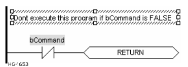
Label - This function is used to break the execution of the program and jump to a desired place in the program. It must have a unique name within the diagram. This operation would be the destination for the corresponding Jump operation.
Jump - This function is used to break the execution of the program and jump to a desired place in the program. It must have the same name as declared using the destination Label operation within the diagram.
Contact -This must be attached to a declared Boolean variable or after placing this symbol on the diagram a Boolean variable should be declared as a contact.
Coil -This must be attached to a declared Boolean variable or after placing this symbol on the diagram a Boolean variable should be declared as a coil.
Symbols of variables and instances are selected using the variable list, that can be used as the variable editor. The user can simply enter a symbol or constant expression in the edit box and press OK. The user also can select a name in the list of declared object, or declare a new variable by pressing the "Create" button.
Return to the Top: Function Block Diagram (FBD)
FBD Comments
Comment text areas can be entered anywhere in a FBD diagram. Press the following button in the FBD toolbar for inserting a new comment area:
Insert Comment Text -In this mode, the mouse is used for inserting comment text areas in the diagram. Comment texts can be entered anywhere. Click in the diagram and drag the text block to the wished position. Double click on the comment area for entering or changing the attached text. When selected, comment texts can be resized, see Resizing FBD Objects.
FBD Corners
Corners are used to force the routing of connection lines, as the FBD editor imposes a default routing only between two pins or user defined corners. All variable symbols and are entered in FBD diagrams using small boxes. Press the following button in the FBD toolbar for inserting a corner on a line:
Insert Corner: In this mode, the mouse is used for inserting a user defined corner on a line. The user can drag a new line from an output pin to an empty space. In that case the editor automatically finished the line with a user defined corner so that the user can continue drawing the connection to the wished pin and force the routing while drawing the line. Corners can then be selected and moved to change the routing of existing lines.
FBD Network Breaks
Network breaks can be entered anywhere in a FBD diagram. Breaks have no meaning for the execution of the program. They just help the understanding of big diagrams, by splitting them in a list of networks. Press the following button in the FBD toolbar for inserting a new break:
Insert Network Break: In this mode, the mouse is used for inserting a horizontal line that acts as a break in the diagram. The break line is drawn on the whole diagram width. No other object can overlap a network break. Break lines can then be selected and moved vertically to another location. etwork breaks can also be used for browsing the diagram. Press Ctrl+Page Up or Ctrl+Page Down keys to move the selection to the next or previous network break.
FBD "OR" Vertical Rail
The FBD editor enables the drawing of LD rungs. A particular object, the "OR" rail can be inserted on a rung in order to connect parallel contacts together press the following button in the FBD toolbar for inserting a new "OR" rail:
Insert "OR" rail: In this mode, the mouse is used for inserting a rail that collects several Boolean data flows for an "OR" operation, in order to insert parallel contacts such as done in Ladder Diagrams. The "OR" rail has exactly the same meaning as an "OR" block regarding the execution of the diagram.
Return to the Top: Function Block Diagram (FBD)
Drawing FBD Connection Lines
Press this button before inserting a new line. The editor enables users to terminate a connection line with a Boolean negation represented by a small circle. To set or remove the Boolean negation, select the line and press the SPACE bar.
Example:
Connection lines must always be drawn in the direction of the data flow: from an output pin to an input pin. The FBD editor automatically selects the best routing for the new line. Connection lines indicate a data flow between the following possible objects:
Block - Refer to the help on the block for the description of its input and output pins, and the expected data types for the coherency of the diagram. See also Function Block Calls in IEC Editors and Basic Operations.
Variable - Variables can be connected on their right side (to initiate a flow) or on their left side for forcing the variable, if it is not "read only". The flow must fit the data type of the variable.
Jump - A jump must be connected on its left side to a Boolean data flow.
Left Power Rail - Left power rails represent a TRUE state and can be connected to a non limited number of objects on their right side.
Contact - A contact must be connected on its left side and on its right side to Boolean data flows.
"OR" Rail - Such rail that collects several Boolean data flows for an "OR" operation, in order to insert parallel contacts such as done in Ladder Diagrams. It may have several connections on its left side and on its right side. All connected data flows must be Boolean.
Coil - A coil must be connected on its left side to a Boolean data flow. It is not mandatory that a coil be connected on its right side.
Right Power Rail - A right power rail is an element of the LD language, and is commonly used for terminating Boolean data flows. It has a non limited number of connections on its left side. It is not mandatory to connect coils to power rails.
Moving or Copying FBD Objects
Press this button or press ESCAPE before any selection. The FBD editor fully supports drag and drop for moving or copying objects. To move objects, select them and simply drag them to the wished position.
To copy objects, the user may do the same, and just press the CONTROL key while dragging. It is also possible to drag pieces of diagrams from a program to another if both are open and visible on the screen. At any moment while dragging objects the user can press ESCAPE to cancel the operation.
Alternatively, the user can use classical Copy/Cut/Paste commands from the Edit menu. When the user run the Paste command, the editors turns in "Paste" mode, with a special mouse cursor. Click in the diagram and move the mouse cursor to the wished position for inserting pasted objects.
Return to the Top: Function Block Diagram (FBD)
Resizing FBD Objects
Press this button or press ESCAPE before any selection. When an object is selected, small square boxes indicates the user how to resize it with the mouse. Click on the small square boxes for resizing the object in the wished direction.
Not all objects can be resized. The following table indicates possible operations:
| FBD Variables | Horizontally and Vertically (*) |
| Block | Horizontally |
| And | Horizontally |
| FBD "OR" Vertical Rail | Vertically (before connecting elements to them) |
| FBD Comments Area | In all directions |
(*) Resizing a variable box vertically enables the user to display together with the variable name its tag (short comment text), its description text, plus its I/O location it the variable is mapped to an I/O channel. The variable name is always displayed at the bottom of the rectangle:
Return to the Top: Function Block Diagram (FBD)
Viewing FBD Diagrams
The diagram is entered in a logical grid. All objects are snapped to the grid. At any moment the user can use the System > Settings > Zoom menu option for zooming to 100%, 125% or 150 in the edited diagram. The user also can press the [ + ] and [ - ] keys of the numerical keypad for zooming the diagram in or out.
Using the Keyboard - FBD
| Moving Objects via Keyboard | |
|---|---|
| When graphic objects are selected, the user can move them in the diagram by hitting the following keys: | |
| Shift + Up | Move to the top |
| Shift + Down | Move to the bottom |
| Shift + Left | Move to the left |
| Shift + Right | Move to the right |
| When an object is selected, the user can extend the selection by hitting the following keys: | |
| Shift + Ctrl + Home | Extend to the top: select all objects before the selected one |
| Shift + Ctrl + End | Extend to the bottom: select all objects after the selected one |
|
To insert or delete space in the diagram, the user can simply select an object, press Shift+Control+End to extend the selection and then move selected objects up or down |
|
| Auto Alignment via Keyboard | |
|---|---|
| When objects are selected, the following keystrokes automatically align them: | |
| Ctrl+ Up | To the top |
| Ctrl + Down | To the bottom |
| Ctrl + Left | To the left |
| Ctrl + Right | To the right |
Return to the Top: Function Block Diagram (FBD)
Inserting FBD Objects on a Line
The FBD editor enables the users to insert an object on an existing line and automatically connect it to the line. This feature is available for all objects having one input pin and one output pin, such as variable boxes, contacts and coils. This feature is mainly useful when entering pieces of Ladder Diagrams. Just draw a horizontal line between left and right power rails: this is the rung. Then the user can simply insert contacts and coils on the line to build the LD rung.
LD Symbols
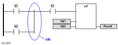
LD symbols may also be entered in FBD diagrams and linked to FBD objects. Special vertical lines are available in FBD language for representing the merging of LD parallel lines. Such vertical lines represent a OR operation between the connected inputs. Below is an example of an OR vertical line used in a FBD diagram:
Return to the Top: Function Block Diagram (FBD)