Logic Editor
See also: User Settings for Advanced Ladder Overview
See also: Advanced Ladder Logic Programming
Topic Menu
User Settings for theAdvanced Ladder with Register Based Addressing Editor and the Advanced Ladder with Variable Based Addressing Editor can be accessed from any one of the following options:
-
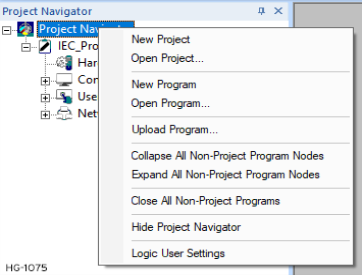
Option 1: Right-click on Project Navigator and select Logic User Settings from the option displayed.
-
Option 2: Right-click on Program and select Logic User Settings from the option displayed.

Selecting the Logic Editor tab brings up the following options:
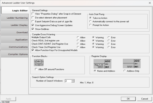
General Settings for Logic Editor
-
View “Properties dialog” after Snap-in of element: If this option is selected, Cscape automatically opens the Properties dialog upon element placement in the logic to allow the user to immediately set the element’s properties.
Note: This action can be over-ridden by holding down the SHIFT key when the element is placed.
De-select element after placement: If this option is not selected, Cscape will "retain" the most recently selected element type, as indicated by the cursor. This is very convenient when many I/O points of the same type need to be placed quickly.If this option is selected, Cscape will de-select the element type after each placement. It is then necessary to select a new element type before each placement. When placing an element this option can be temporarily switched on, by holding the SHIFT key while left clicking the mouse to place the element.
-
Export Setpoint Data as a part of .pgm file: If this option is selected, the setpoint data is also included while exporting to removable media using the System > To PGM option.
-
Use Aggressive Debug Screen Updates: If this option is selected, Cscape updates the entire screen while debugging not just the blocks of data that change. However, it uses more CPU time. This option is used when the screen does not update properly when debugging.
-
Show Gridlines:If this option is selected, gridlines are shown in the ladder editing area to delineate columns and rows. The user can also enable / disable gridlines from the System > Grid Lines option.
Return to the Top: Logic Editor
Auto Start Rung
Take no Action: If this option is selected, no action will be taken when the user places an element in the middle of the ladder logic area.
Automatically connect to the power rail: If this option is selected, whenever the user places an element anywhere in the logic area, a rung will be created automatically i.e., the element will get connected to the power rail automatically.
Prompt for Action: If this option is selected, whenever the user places an element anywhere in the logic area, Cscape will prompt for whether or not a new rung should be created. Action is taken depending on user input.
Compiler Errors/Warning
Note: There are three (3) possible sources of errors in a Ladder Program:
-
Syntax Errors - Caused by poor entry or misuse of program elements. Example: Creating a rung with only a single Input Contact (-| |- , -|/|-) on the rung.
-
Logical Errors - Caused by asking the controller to do something it can't or using the wrong information. Example: Triggering a timer from %I1 when the user have used %I2.
-
Physical Errors - Caused by misunderstanding or misuse of the hardware, especially the physical I/O points.
Cscape error-checks the program before compiling the program for download, for export, or when the user initiates an error check. Several conditions can be configured to be Errors, Warnings, or Allowed without notification from the error checker.
Allow: This condition will not be considered a problem if present and the program will be compiled without notification of this condition
Warning: This condition will generate a warning when compiling, but will not prevent compiling and downloading of the program.
Error: This condition will generate an error and will not allow compiling or downloading until the condition is resolved.
-
Multiple Output Coils: Due to the nature of Ladder Logic and the order of the logic scan, an output coil assigned to any given address or variable normally should only be used in one place within the entire program. However, some users may wish to exploit the known issues with having multiple output coils as such.
-
Check REAL
 These numbers use IEEE 754-1985 format to store numbers in following ranges.
32-bit single-precision floating point (REAL) – -3.40282E+38 to +3.40282E+38
64-bit double-precision floating point (LREAL) – -1.79769E+308 to +1.7976E+308
Floating Point refers to both REAL and LREAL data types. 2nd register use: REAL data types use 2 consecutive registers to occupy 32 bits of space while LREAL data types use 4 consecutive registers to occupy 64 bits of space.Should the user attempt to use one of the extended registers by itself, it is possible to overwrite and invalidate the REAL/LREAL data. There is rarely a reason to allow this.
These numbers use IEEE 754-1985 format to store numbers in following ranges.
32-bit single-precision floating point (REAL) – -3.40282E+38 to +3.40282E+38
64-bit double-precision floating point (LREAL) – -1.79769E+308 to +1.7976E+308
Floating Point refers to both REAL and LREAL data types. 2nd register use: REAL data types use 2 consecutive registers to occupy 32 bits of space while LREAL data types use 4 consecutive registers to occupy 64 bits of space.Should the user attempt to use one of the extended registers by itself, it is possible to overwrite and invalidate the REAL/LREAL data. There is rarely a reason to allow this. -
Check DINT
Double Integer - [Data Type DINT] - A 32-bit signed value. Double Integers are used where the value of the data is expected to be in the range of -2,147,483,648 to +2,147,483,647. / UDINT Unsigned Double Integer - [Data Type UDINT] - A 32-bit unsigned value. Unsigned Double Integers are used where the value of the data is expected to be in the range of 0 (zero) to 4,294,967,296. 2nd register use: DINT and UDINT data types use 2 consecutive registers. Should the user attempt to use one of the extended registers by itself, it is possible to overwrite and invalidate the DINT/UDINT data. However, it is somewhat common to exploit known behavior in bitwise functions or otherwise in order to access the "low word" of a DINT/UDINT. -
Check Timer 2nd register use: Timers and Counters use 2-3 consecutive registers. While the first register (or first 2 registers for 32-bit functions) contains the accumulator
A register/variable used to gather or accumulate a total of time, counts, items, or events. of the Timer/Counter, the second register (or 3rd register for 32-bit functions) mostly consists of data the function requires in order to function properly; overwriting that data will cause erroneous behavior in the Timer/Counter. There is rarely a need to access that 2nd (or 3rd) register. -
Allow Function Keys for Unsupported Models: If unchecked, Cscape will not allow, for example, an XL4 (F1-F4 available on keypad) to use %K5 (F5) or higher. If this option is checked, Cscape will allow any unsupported function keys configured for any models. This makes it easier to port an existing program for an older controller with, for example, 7 F-keys into a newer controller with less F-keys without needing to alter the program to delete references to the extra function keys.
Function Blocks
Allow OR around functions: Functions blocks can optionally be "ORed" around using contacts if this option is set, otherwise "ORing" around function blocks will produce an error. The error consists entirely of notice that this option is not checked.
Variable Display
The Variable Display option allows the user to select whether or not register Names are displayed on the screen. Display of Register Names is very useful but can clutter the screen.
-
Name and Address: Selecting this option displays both register address and name assigned to the register.
-
Address Only: Selecting this option displays only Register's Type and Offset address.
Search Option Settings
Number of Search Windows: This option specifies the number of search windows that are allowed to be open when using the Find functionality. Minimum 1 and Maximum 8 search windows can be displayed.
Note: Enabling/disabling of this option from Logic Editor Settings should get reflected in Home > Find and Replace > Find window as well.
Return to the Top: Logic Editor