Serial Modbus Slave in Advanced Ladder 
See also: Serial Communication in Advanced Ladder
See also: Project Toolbox for Advanced Ladder
Topic Menu
Serial Modbus Slave Overview
-
The Modbus Slave Communications function is used to make the OCS controller available as a Modbus Slave over a serial connection. See also: Ethernet Configuration Overview.
-
This function must be used in conjunction with the Open Communication Port function [see: Serial Communication in Advanced Ladder], which must open the port for either the Modbus RTU or Modbus ASCII protocol prior to using the Modbus Slave Communications function.
-
In addition to basic Modbus Slave availability, Write Inhibiting, Exception Messaging, and a Store and Forward feature are available through optional configuration.
-
There is not currently another way of opening a serial port for Modbus Slave communications.
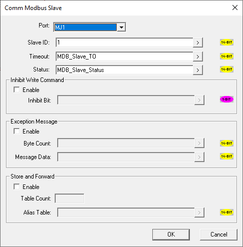
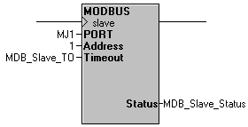
Port: The port to use as a Modbus Slave, having previously been opened with the Open Communication Port function [LINK: Open Comm Port]
Slave ID: A constant value or a variable/register that determines the Slave address of this OCS. The valid Slave ID range for constant value addresses is 1 to 247. An extended range from 1 to 9999 may be used with a variable/register reference, caveats apply. See also: Extended Addressing for Serial Modbus
Timeout: A constant value or variable/register that determines when this OCS will indicate that no activity has happened via the Status register. Value is in 100ms resolution, i.e. 25 = 2.5s
Status: A variable/register that will contain the status of the OCS as a Modbus Slave.
Basic Operation: Once a port has been opened with the Open Communication Port function [see: Serial Communication in Advanced Ladder], and specified for use with either the Modbus RTU or Modbus ASCII protocol, this function is intended to be powered at all times, making the OCS available to Modbus commands from a Modbus Master device.
All data by register reference is available via Modbus. For Variable Based Ladder Logic, variables must be tagged to a register to make the data available. For Modbus functions supported and address mapping see: Ethernet Configuration Overview
Status: The status register reports normal operation by toggling the 4th bit, “Valid Message Received”. A lack of Modbus activity that exceeds the timeout parameter will cause the 1st bit to come on until further activity occurs. Setting the timeout parameter to 0 will disable the timeout status bit.
Return to the Top: Serial Modbus Slave in Advanced Ladder
Status Bit assignment for Serial Modbus
|
Bit Number |
Status |
|
1 |
Inactivity Timeout |
|
2 |
Store and Forward command sent (toggle) |
|
3 |
Store and Forward response sent (toggle) |
|
4 |
Valid message received (toggles) |
|
5 |
Parity error (single pass) |
|
6 |
Frame Error (single pass) |
|
7 |
Overrun error (single pass) |
|
8 |
Crc/Check sum error (single pass) |
|
9 |
Exception message send (reset when e_cnt = 0) |
|
10 |
Exception message exceeds send buffer size (reset when e_cnt = 0) |
|
11 |
Attempt to send exception message when transmit busy (reset when e_cnt = 0) |
Note: Each bit of a 16-bit variable/register may be addressed separately in logic
-
VariableName.1 = the 1st bit of VariableName, VariableName.16 = the 16th bit of VariableName
-
%R1.1 = the 1st bit of %R1, %R1.16 = the 16th bit of %R1, etc.
Return to the Top: Serial Modbus Slave in Advanced Ladder
Extended Addressing for Serial Modbus
Using addresses from 1 to 9999 is possible when using a variable/register for the Address parameter. However, if also using the following addresses in the normal range of 1 to 247 elsewhere on the Modbus network, certain corresponding ranges of extended addresses cannot be used:
| If in use | Extended Range off-limits |
|
If in use | Extended Range off-limits | ||
|
1 |
256 |
511 |
21 |
5376 |
5631 |
|
|
2 |
512 |
767 |
22 |
5632 |
5887 |
|
|
3 |
768 |
1023 |
23 |
5888 |
6143 |
|
|
4 |
1024 |
1279 |
24 |
6144 |
6399 |
|
|
5 |
1280 |
1535 |
25 |
6400 |
6655 |
|
|
6 |
1536 |
1791 |
26 |
6656 |
6911 |
|
|
7 |
1792 |
2047 |
27 |
6912 |
7167 |
|
|
8 |
2048 |
2303 |
28 |
7168 |
7423 |
|
|
9 |
2304 |
2559 |
29 |
7424 |
7679 |
|
|
10 |
2560 |
2815 |
30 |
7680 |
7935 |
|
|
11 |
2816 |
3071 |
31 |
7936 |
8191 |
|
|
12 |
3072 |
3327 |
32 |
8192 |
8447 |
|
|
13 |
3328 |
3583 |
33 |
8448 |
8703 |
|
|
14 |
3584 |
3839 |
34 |
8704 |
8959 |
|
|
15 |
3840 |
4095 |
35 |
8960 |
9215 |
|
|
16 |
4096 |
4351 |
36 |
9216 |
9471 |
|
|
17 |
4352 |
4607 |
37 |
9472 |
9727 |
|
|
18 |
4608 |
4863 |
38 |
9728 |
9983 |
|
|
19 |
4864 |
5119 |
39 |
9984 |
9999 |
|
|
20 |
5120 |
5375 |
|
|
|
|
Optional Parameter – Inhibit Write Command:
-
Inhibit Bit: When Inhibit Write Command is enabled, this 1-bit variable/register will determine when to disallow a Modbus Master device to write any data to this OCS. Upon such requests while inhibiting, the OCS will return an error to the Modbus Master indicating “Invalid or Unsupported Function”.
Optional Parameters – Exception Message:
-
Byte Count: When Exception Message is enabled, this variable/register acts to indicate how many bytes to send in one Exception Message. Transition of this value from zero to non-zero also acts as a trigger for a single Exception Message.
-
Message Data: This array/register contains the data sent in the Exception Message.
Return to the Top: Serial Modbus Slave in Advanced Ladder
Exception Message Operation
Exception Messaging, aka Report-on-Exception, is a method of immediately informing the master that the slave has important information pending. This method is typically used in applications where modems are used as the communication channel, and the slaves are polled![]() Polled - When a device is consistently asked for data, either as fast as possible or on a time basis. Normally associated with Modbus communications. for data between long intervals. To start a Report-on-Exception sequence, the ladder program must establish a connection with the master typically through the Modem function block (See: Serial Modem Control in Advanced Ladder .) Once the connection is established, the master and slave require some cooperative functionality on determining the address of the slave calling. Since this functionality is not standardized or a part of the Modbus protocol, the Modbus function contains two alternate methods such that the one most appropriate for the master is selected.
Polled - When a device is consistently asked for data, either as fast as possible or on a time basis. Normally associated with Modbus communications. for data between long intervals. To start a Report-on-Exception sequence, the ladder program must establish a connection with the master typically through the Modem function block (See: Serial Modem Control in Advanced Ladder .) Once the connection is established, the master and slave require some cooperative functionality on determining the address of the slave calling. Since this functionality is not standardized or a part of the Modbus protocol, the Modbus function contains two alternate methods such that the one most appropriate for the master is selected.
The first method is best used when the Modbus Master device is a Horner Modbus Master. This method involves the slave responding to the non-standard Modbus request Get Slave Address, which is broadcast by the master after the connection is established.
Note: Since this is just a response to a Modbus request, this method does not require that Exception Messaging be enabled in the Modbus function parameter block. Use of this method with a non-Horner Modbus Master device can require that master to be modified to support this command. The Modbus request and response frames are presented below:
Request:
|
ADDR |
FUNC |
|
0 |
65 (41H) |
Response:
|
ADDR |
FUNC |
DATA |
|
(SLAVE ADDR) |
65(41H) |
(SLAVE ADDR) |
The second method involves the slave sending an unsolicited response (Exception Message) to the master once the connection is established. This method is enabled by checking the Exception Message Enable check box in the Modbus function parameter block. Once enabled, two additional inputs (Byte Count and Message Data) are visible and control the sending of the Exception Message.
The Message Data input contains the reference to the word array (byte loaded), which contains the Exception Message. The specific byte pattern used for the Exception Message depends on that supported by the master. When sent, the appropriate header and checksums are inserted automatically by the Modbus function and do NOT need to be included in the message data. The Byte Count specifies the number of bytes in the Message Data reference to send. The Byte Count also acts as the trigger that starts the transmission of the response. When the Byte Count transitions from zero to a specific number, that number of bytes are sent. Once transmitted, the Modbus function responds to master requests as expected.
Two faults can occur when attempting to send an Exception message. The first fault is created by setting the Byte Count to a value that exceeds 255. The second is created by attempting to send an Exception message when the Modbus function is currently in the process of sending a reply to a previous request. Should a fault occur, the message is NOT sent, and the appropriate bit is set in the status word. The fault indication bits remain set until the "Byte Count" is returned to zero
Optional Parameters – Store and Forward:
-
Table Count: Constant value in the range from 1 to 253 specifying the number of words in the Alias Table
-
Alias Table: Array/registers containing the alias table. The target address is stored in the bottom byte of each word and the alias address is stored in the top byte of each word.
Return to the Top: Serial Modbus Slave in Advanced Ladder
Store and Forward Operation
The Store and Forward feature allows extending the coverage range when using radio modems by allowing an OCS Modbus slave to act as a radio repeater using a single communications port.
This method requires the Modbus master to address requests to the out-of-range slave with an alias address. When a designated Store and Forward slave detects the request with the alias address, it reconstructs the request with the actual address and retransmits the request acting as a repeater. Once the targeted node responds, the Store and Forward slave reconstructs the response with the alias address and retransmits the response to the master. Any Store and Forward slave may service one or more out-of-range slave(s).
To enable the Store and Forward feature on an OCS slave, the Modbus slave function block must be enabled for Store and Forward operation and contain the starting array/register reference and size of the associated alias table. Then a Modbus address alias table must be constructed in the specified array/registers.
|
Example Alias Table |
||
|
Register |
High 8 bits (alias address) |
Low 8 bits (target address) |
|
%R101 |
15 |
5 |
|
%R102 |
16 |
6 |
|
%R103 |
31 |
12 |
Once the Modbus slave function is configured and enabled, the reception of a valid request whose target address does not match the configured slave’s address causes a search of the alias table. If an alias is found that matches the message address, the Modbus request is reconstructed with the corresponding target address and is retransmitted. If an alias match is not found, the slave takes no action.
If configured for Store and Forward and the slave receives a request whose target address does match the configured slave’s address, the slave locally processes and replies to the request as expected. Table entries with the value of zero (reserved for future alias assignment) are ignored.
Note: The master must be capable of ignoring received requests with a different request address other than that of the targeted (alias) address.
Store and Forward nodes pass all communication requests and responses between the master and the target. However, if a request is forwarded and a response is not received from the target slave, the forwarding node does not send any type of error response. However, toggles are provided in the slave function block status registers to indicate when command and response messages are forwarded. These bits could be used by the application to construct message counters or provide more complex message management.
Return to the Top: Serial Modbus Slave in Advanced Ladder
Modbus Master Mapping
To access OCS registers, a Modbus Master must be configured with the appropriate register type and offset. This is usually accomplished with one of two methods:
The first method uses Traditional Modbus References, in which the high digit represents the register type and the lower digits represent the register offset (starting with register 1 for each type). Since only four register types can be represented in this manner, OCS Modbus Function Blocks pack several OCS register types into each Modbus register type. Starting addresses of each OCS register type are shown in the Traditional Modbus Reference column of the table below.
The second method requires the Modbus Master to be configured with a specific Modbus Command and Modbus Offset. The supported Modbus commands and the associated offsets are also illustrated in the table.
|
OCS Reference |
Maximum Range |
Traditional Modbus Reference |
Modbus Command(s) |
Modbus Offset |
|---|---|---|---|---|
| %I1 | 2048 | 10001 | Read Input Status (2) | 00000 |
| %IG1 | 256 | 13001 | 03000 | |
| %S1 | 256 | 14001 | 04000 | |
| %K1 | 256 | 15001 | 05000 | |
| %Q1 | 2048 | 00001 |
Read Coil Status (1) Force Coil (5) Force Multiple Coils (15) |
00000 |
| %M1 | 2048 | 03001 | 03000 | |
| %T1 | 2048 | 06001 | 06000 | |
| %QG1 | 256 | 09001 | 09000 | |
| %AI1 | 512 | 30001 | Read Input Register (4) | 00000 |
| %AIG1 | 32 | 33001 | 03000 | |
| %SR1 | 32 | 34001 | 04000 | |
| %AQ1 | 512 | 40001 |
Read Holding Register (3) Load Register (6) Load Multiple Registers (16) |
00000 |
| %R1 | 2488 | 40513 | 00000 | |
| %R1 | 2048 | 43001 | 03000 | |
| %AQG1 | 32 | 46001 | 06000 | |
| %R1 | 9999 | 410001¹ | 10000 |
¹Extended register range only available on later firmware versions.
Return to the Top: Serial Modbus Slave in Advanced Ladder