Serial Modem Control in Advanced Ladder 
See also: Serial Communication in Advanced Ladder
See also: Project Toolbox for Advanced Ladder
Topic Menu
Serial Modem Overview
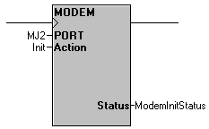
The Modem Communication Control function allows the OCS to control an attached modem. It allows one of three modes of controlling the modem as noted below. Only one Modem Communication Control function may be in use at any given time.
General Function Status and Power Flow: All iterations of the Modem Communication Control provide the same INT status and power flow through the function as below. See each of the three function modes following for details on each mode.
-1 – The function is not active, output from the function block is OFF.
-2 – The function is being executed; the output remains OFF.
-3 – The function timed-out because the modem did not respond; the output remains OFF.
0 – The modem accepted the command; the output depends on the function.
1 – The modem successfully connected; the output turns ON.
2 – An incoming ring is detected; the output remains OFF.
3 – The modem has lost the carrier; the output turns OFF.
4 – The command has produced an error; the output remains OFF.
Return to the Top: Serial Modem Control in Advanced Ladder
Initialize Modem
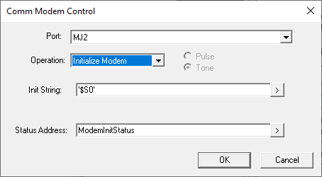
Port: The port to which a modem is connected
Operation: Initialize Modem selected for this Help section
Init String: A constant “hard-coded” string or an array/register where the initialization string may be found. Do not include the standard “AT” string starter, it is implied and will be removed for constant entries. For Variable Based Ladder Logic, constant entries must be encompassed by single quotes.
Status Address: Variable/register where a status will be updated based on the state of the function.
Operation: When the input to the Initialize Modem function block transitions from OFF to ON, the controller sends the initialization string to the modem. If the modem returns an OK response, the output of the function block turns ON, and the status register is loaded with 0. If the modem returns an error response because the init string is not valid, the status register is loaded with a 4. If the modem does not respond, the status is loaded with -3 indicating a timeout.
Return to the Top: Serial Modem Control in Advanced Ladder
Auto Dial
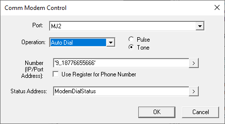
Port: The port to which a modem is connected
Operation: Auto Dial selected for this Help section
Number (IP/Port Address): A constant “hard-coded” string or an array/register where the number to dial may be found. For Variable Based Ladder Logic, constant entries must be encompassed by single quotes.
Use Register for Phone Number: Must be checked to use an array/register for the “Number” parameter
Status Address: Variable/register where a status will be updated based on the state of the function.
Operation:
-
When the input to this function block transitions from OFF to ON, the controller attempts to dial the modem with the supplied phone number. If the modem dials and successfully connects to another modem, the output of the function block turns ON, and status is loaded with 1 to indicate a connection. Keeping power flow to the dial function block allows the controller to monitor the connection.
-
If the connection is lost (the other side hangs-up...), the output to the function block turns OFF and the status is loaded with 3 to indicate a loss of carrier.
-
If the input to this function block transitions from ON to OFF, the modem hangs up, the function block output turns OFF, and the status is loaded with -1 to show the function block is inactive.
Return to the Top: Serial Modem Control in Advanced Ladder
Auto Answer
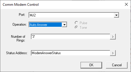
Port: The port to which a modem is connected
Operation: Auto Answer selected for this Help section
Init String: A constant “hard-coded” string or an array/register where the number of rings before answering is specified. For Variable Based Ladder Logic, constant entries must be encompassed by single quotes.
Status Address: Variable/register where a status will be updated based on the state of the function.
Operation:
-
When the input to this function block transitions from OFF to ON, the controller attempts to set the modem to auto answer mode. When the modem has been placed in auto answer mode, the function block output remains OFF, and the status is loaded with 0 to indicate the modem is OK. Power flow into the function block must be kept ON at this point.
-
When an incoming call is received, the output of the function block remains OFF, and the status is loaded with 2 to indicate ringing. After the programmed number of rings, the modem answers. If a connection is established, the output of the function block turns ON and the status is loaded with 1 to indicate a connection.
-
If the connection is lost, (other side hangs-up ...) the output turns OFF and the status is loaded with 3 to indicate a loss of carrier.
-
If the modem is connected to another device and the input to the function block transitions from ON to OFF, the modem hangs-up, the function block output turns OFF, and the status is loaded with -1 to show the function block is inactive.
Return to the Top: Serial Modem Control in Advanced Ladder
Controller to Modem Cable
The following is a diagram of a cable necessary to connect a modem to an OCS controller MJ port. A port where RTS and CTS lines are available is required. It is necessary to construct this cable or purchase it from an outside supplier.
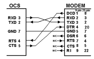
-
The wire type used is not overly critical, except that the maximum length of the cable must be kept between 30 and 50 feet (10 to 15 meters). In all cases the cable must be shielded multi-conductor with conductors of at least 20 gauge. The length of the cable must be as short as possible, and in no case, longer than 50 feet (15 meters).
-
The modem must be located as close as possible to the OCS, preferably less than one meter. However, EIA-232 specifications allow for cable runs up to 50 feet (15 meters). If cable lengths longer than 30 feet (10 meters) are required, a special low capacitance cable must be used.
-
The OCS MJ port does not have the DCD and DSR signals so the RTS/CTS handshaking lines must be used. This prevents hardware handshaking from being used with a modem on these devices.
-
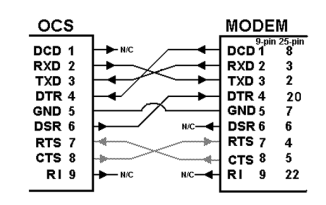
For older OCS models with 9-pin DSUB ports onboard, the following is a diagram of a cable necessary to connect a modem to an OCS /RCS controller. It is necessary to construct this cable or purchase it from an outside supplier.
-
If the modem has a DB25 connector, one may need to supply a 9-to-25-pin adapter.
-
The grayed connections are used only if hardware handshaking between the controller and modem is required.
Warning: Damage can result if the CD and RI lines are connected to each other or to any other signal on the connector, or through the cable to the other unit.
CAN I USE A NULL MODEM CABLE?
No. In order to connect a modem to the OCS the controller to modem cable must be constructed or purchased. A Null Modem cable provides connections between the DCD and DSR, and the two RI lines are connected together. This situation can damage the OCS , the modem, or both.
Return to the Top: Serial Modem Control in Advanced Ladder