Alarm Configuration (Graphical) for Canvas
Note: For Canvas Series only. For all other series see Alarm Configuration (Graphical) .
See also: User Interface
See also: Graphic Object Toolbox for Canvas Series
Topic Menu
Overview of Alarm Configuration

|
Datalogging & Alarm Handling |

|
Energy Monitoring Application: Cscape Example |

|
Combustion Boiler Control Cscape Example |
Alarms are messages that are presented to the operator in response to a specific condition in the control system. On receiving an alarm, the operator is generally expected to take immediate corrective action and record that action by acknowledging or clearing the alarm. In addition, the alarm system also records these events to a history log such that a supervisor can review the number of alarm occurrences or the operator’s response to such alarms.
-
The Graphical Alarm System is actually three separate parts that includes an alarm manager, an alarm object, and an Alarm Viewer.
-
The Alarm Manager is a task, which runs invisibly in the background and continuously monitors the configured alarm points for a change to the active state. If an alarm point goes active, the alarm manager records that alarm along with a time/date stamp in both a summary and history alarm log.
-
The Alarm Object is a graphical object that can be placed on either a user screen or alarm screen. This object is used to notify the operator that an unacknowledged, active or an alarm entry exists. On detection of an unacknowledged alarm, the operator can touch (select) the alarm object to display the alarm viewer.
-
In the Alarm Viewer, the operator is presented with the list of current alarm entries along with the controls to select, acknowledge, or clear alarm entries.
Return to the Top: Alarm Configuration (Graphical) for Canvas
Alarm Points
Alarm points are single-bit OCS controller registers. Up to 128 (2048 alarms) consecutive single-bit controller registers can be configured for continuous monitoring by the alarm manager. During system configuration, the starting controller register and the number of consecutive registers that make up the alarm points must be specified. Also, during configuration, each alarm point requires an identification string, severity, alarm info, and a group number.
Once the program is loaded and the OCS is in RUN mode, the alarm manager begins monitoring each single-bit register for a transition to an active high. On detection of such transition, the alarm manager changes that alarm point’s state and creates an alarm entry in both alarm logs. Each alarm log entry is loaded with the alarm point identification string, group, severity, alarm info, state and the time and date of the transition.
Note: Maximum Numbers of Alarms supported is based on the controller selected in Hardware configuration.
Alarm State
The alarm state of an alarm point indicates if it is active and if it has been acknowledged or cleared by the operator. An alarm point is in one of four states:
-
ALM - Alarm point is active and is pending acknowledgment.
-
ACK - Alarm point is active and has been acknowledged.
-
RTN - Alarm point has transitioned from active to inactive (return-to-normal) while still pending acknowledgment.
-
CLR - Alarm point is inactive and has no pending request for acknowledgment <or> Alarm point is active but has been cleared.
On the first detection of an alarm point going active, the associated state changes from CLR to ALM. That alarm’s state thereafter only changes on one of three events: the operator acknowledges the alarm, the operator clears the alarm, or the alarm point returns to inactive without being acknowledged.
-
If acknowledged, the alarm state changes to ACK and remains in that state until the alarm goes inactive and changes to CLR.
-
If cleared, the alarm state changes to CLR and remains in that state until the alarm point makes a transition from inactive to active.
-
If the alarm point goes inactive without being acknowledged, the alarm state changes to RTN. Generally, the alarm point remains in that state until either it is acknowledged, cleared, or the alarm points go active. However, if the Alarm Configuration parameter “RTN Implies ACK” is set, the alarm state thereafter immediately changes CLR.
Alarm Logs
A log is portion of internal OCS memory that contains alarm information. The alarm manager maintains two alarm logs that are referred to as the summary and history log. While the differences between the two logs are detailed below, generally the summary log contains the current active and unacknowledged alarms while the history log contains a history of alarm state changes. Each alarm log entry contains the alarm point identifier, time, date, state, alarm info, severity, and group number of the alarm. The time and date indicates the moment the alarm transitioned to the current state. Alarm log entries can be viewed (through group filters) and optionally modified by the operator through the Alarm Viewer.
Return to the Top: Alarm Configuration (Graphical) for Canvas
Alarm Configuration
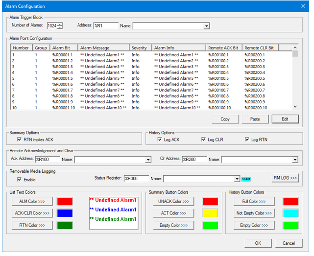
Alarm Trigger Block

-
Number of Alarms - Specifies the consecutive number of alarm points to monitor. The maximum is typically 2048, but it may vary up or down depending on the model.
-
Address - Specifies the starting single-bit controller register address of the first alarm point. Boolean control register specification must begin on a 16-bit boundary. Analog controller register addresses can be specified only if they do NOT include a bit offset. Generally, the selected controller registers need to be non-volatile to prevent possible false alarms at power-up.
-
Name - Allows controller register selection by alias name.
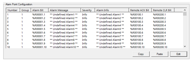
Alarm Point Configuration
-
# – Displays the number of alarms configured.
-
Group – Displays the group number. Default is 1 for all the alarms and this can be modified according to the requirement.
-
Alarm Bit – Displays the list of register bits assigned for each alarm.
-
Alarm Message – This is the alarm text that will be displayed when a particular alarm is triggered.
-
Severity – This option is used to configure the severity of the triggered alarm. The following severity options are available for configuration – Info, Warning, Low, Medium, High and Critical.
-
Alarm Info – This option is used to give a short description about a particular alarm.
-
Remote ACK Bit - Displays the list of configured controller register address to acknowledge the alarm points.
-
Remote CLR Bit - Displays the list of configured controller register address to clear the alarm points.
-
Copy – Selecting this option copies the following alarm data options to clipboard, Number, Group, Alarm Bit, Alarm Message, Severity and Alarm Info.
-
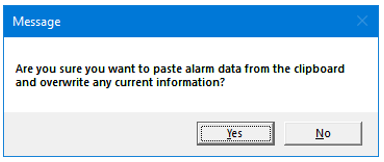
Paste – Selecting this option displays a confirmation window to paste the alarm data information from clipboard. Upon selection of Yes, overwrites the current information.
-
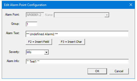
Edit – Selecting this option displays the following window for the selected alarm point.
-
User can modify the alarm point configuration for selected alarm point. Clicking on OK overwrites the current information with the edited information.
-
Alarm Point – Indicates the configured register / variable to trigger an alarm.
-
Group – Indicates the group of an alarm.
-
Alarm Text – Indicates the text that needs to be displayed when that particular alarm is triggered.
-
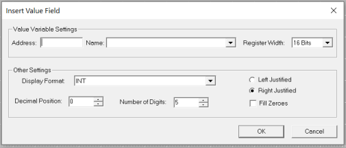
Insert Field (F2) – Selecting this option displays the following window where user can configure any register/variable value in Alarm Text.
-
-
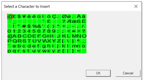
Insert Char (F3) – Selecting this option displays the following window using which user can insert characters in Alarm Text using mouse clicks.
Summary Options

-
RTN implies ACK - This selection forces all alarm points whose alarm state goes RTN (alarm point goes inactive without acknowledge) to immediately change to the CLR state. This prevents RTN entries from appearing in the summary log.
History Options

These selections determine what alarm states are saved to the history file.
Remote Acknowledgment and Clear

-
Ack Address - Specifies the starting single-bit controller register address to acknowledge the alarm points. Boolean
 Boolean- [Data Type BOOL] - A single bit, binary value, or register/variable. Boolean points have only two possible values, 'TRUE' or 'FALSE'. control register specification must begin on a 16-bit boundary. Analog controller register addresses can be specified only if they do NOT include a bit offset. Generally, the selected controller registers need to be non-volatile to prevent possible false alarms at power-up
 -
Name - Allows controller register selection by alias name
-
Clr Address - Specifies the starting single-bit controller register address to clear the alarm points. Boolean control register specification must begin on a 16-bit boundary. Analog controller register addresses can be specified only if they do NOT include a bit offset. Generally, the selected controller registers need to be non-volatile to prevent possible false alarms at power-up
-
Name - Allows controller register selection by alias name
Note: Remote Acknowledge and clear trigger registers can be used to acknowledge and clear individual alarms (i.e., one 16-bit register can acknowledge / clear 16 individual alarms)
Removable Media Logging

-
Enable – Selecting this option enables the removable media logging feature.
-
The Alarm Log feature is designed to allow an application program to log alarm history data to removable media (Micro SD). The data is stored in .CSV (comma separated value) format, which is compatible with 3rd party PC applications, such as Microsoft Excel. Currently Alarm history log can store up to 128 entries in non-volatile memory of the device. These entries are cleared when a program download happens or through operator intervention. This feature saves the alarm history data to Removable media which can be used for offline viewing later and can go beyond 128 entries. Alarms will be logged in the history log as usual however when RM logging is configured, the same history log entry will also be appended to the CSV file at the end.
-
Data logged
The process of recording data over a period of time in order to analyze specific trends or record the data-based events/actions of a system, network, or IT environment. It enables the tracking of all interactions through which data, files, or applications are stored, accessed, or modified on a storage device or application. in the CSV file includes date, time, event (ALARM, RTN, ACK), Alarm Number, Alarm Group and Identifier String. -
Status Register - This will show the status of Alarm logging.
-
Status values:
-
0 – Log completed / nothing to log.
-
11 – Media cannot open
-
12 – Alarm logging is in progress.
-
13 – Make directory error.
-
14 – File open error.
-
15 – File create error.
-
18 – Removable media card full.
-
-
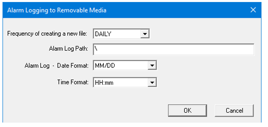
RM LOG >>> - Selecting RM LOG >>> button displays the following window.
-
Frequency of creating a new file - The user can set the frequency of creation of new file where history log entries will be stored in CSV format. A new file can be created daily, weekly, monthly or yearly. If the file is already present at the time of creation, it will be overwritten. The following are the default filenames for creating the file:
-
Alarm_??.CSV where ?? is replaced by
-
1-31 when daily is selected.
-
1-52 when weekly is selected
-
1-12 when monthly is selected
-
last two digits of the year.
-
-
Alarm Log Path - Here the user can provide the directory where Alarm logging files have to be stored. If not entered, the path defaults to”\” in which case the alarm log files will be placed in the root directory. For example, if the Alarm Log Path is configured as \MYFOLD\ALARMS, the alarm log files Alarm_??.CSV will be created in the \ MYFOLD\ALARMS\ folder.
-
Alarm Log – Date Format - The user can select the date formats from the dropdown. The logged data will show the date in the selected format only.
-
Alarm Log – Time Format - The user can select the time formats from the dropdown. The logged data will show the time in the selected format only.
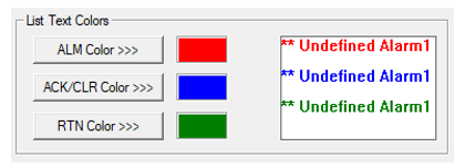
List Text Colors
-
ALM Color >>> - Specifies the color of alarm log entries that are in ALM state.
-
ACK/CLR Color >>> - Specifies the color of alarm log entries that are in ACK or CLR state.
-
RTN Color >>> - Specifies the color of alarm log entries that are in RTN state.
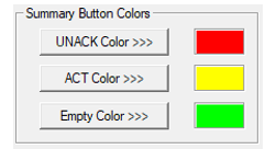
Summary Button Colors - The following only applies to alarm objects whose indicator mode is set to Alarm Button/Icon only:
-
UNACK Color >>> - Specifies the background color of “Summary Button – Icon Only” alarm object type when their associated summary log entries has all alarms in unacknowledged state.
-
ACK Color >>> - Specifies the background color of “Summary Button – Icon Only” alarm object type when their associated summary log has all entries at an active alarm state but NO entries at an unacknowledged alarm state.
-
Empty Color >>> - Specifies the background color of “Summary Button – Icon Only” alarm object type when their associated summary log has NO entries at an active or unacknowledged alarm state.
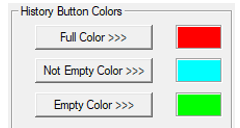
History Button Colors - The following only applies to alarm objects whose indicator mode is set to alarm button/icon only:
-
Full Color >>> - Specifies the background color of “History Button – Icon Only” alarm object type when their associated history log is full.
-
Not Empty Color >>> - Specifies the background color of “History Button – Icon Only” alarm object type when their associated history log has any entries.
-
Empty Color >>> - Specifies the background color of “History Button – Icon Only” alarm object type when their associated history log has no entries.
Return to the Top: Alarm Configuration (Graphical) for Canvas