Register Backup and Restore in Advanced Ladder
See also: Advanced Ladder Logic Programming
See also: Controller Register Types in Advanced Ladder
Topic Menu
Contents of registers/variables can be backed up to a .dat file or can be restored to the controller from an existing .dat file using the Register Backup Utility.
Register Backup and Restore Registers 

Tools > Backup Registers
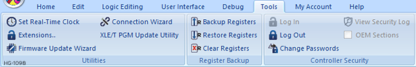
Step 1: Backup Register Contents - Selecting Backup Registers from Tools Menu will invoke a dialog as below:
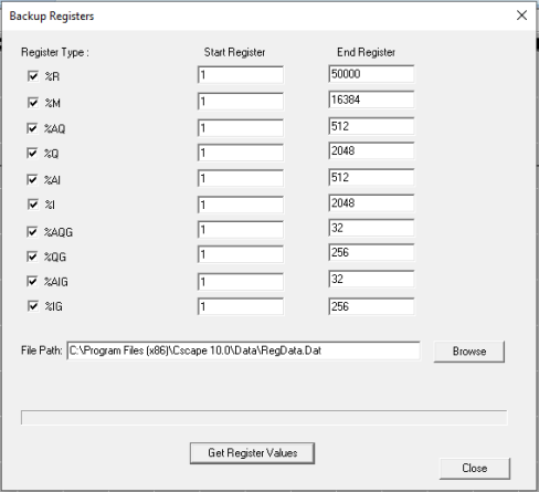
NOTE: The default End Register Address values will be dependent on the target controller type.
Register Type: Select the respective checkboxes for each Register type whose contents are to be backed up.
The required range for the particular type of register can be set using the Start Register Address & End Register Address within the register limits.
- Click Browse button to select the desired location for saving the .dat file.
- Click Get Register Values button to start Backup.
Backing up progress is shown as below:
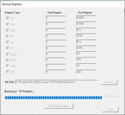
“Register Backup Completed!” message is displayed after completion of the Backing up process.
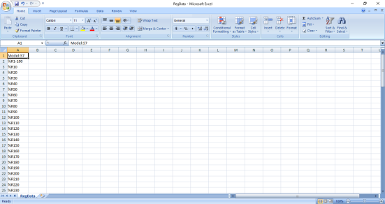
The contents of Registers are now backed up to the .dat file at the specified location on the PC and can be opened in a spreadsheet or text editor for viewing the contents.
Step Two: Restore Register Contents - Selecting Restore Registers from Tools Menu will open the dialog below:
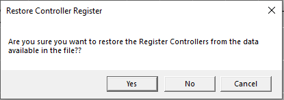
Click Yes button to proceed.
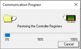
A prompt for the selection of a .dat file will appear. Select the file to restore contents onto the controller and then click Open button. This initiates restoring the controller registers from the specified file.
Controller will not go to STOP mode. Registers are restored gradually along with the progress bar (see image below).
Once completed, the following message will appear:
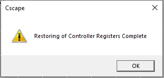
The contents of Registers in the .dat file will be restored to the controller.
Return to the Top: Register Backup and Restore in Advanced Ladder
Controller Register Types in Advanced Ladder
See also: I/O Names
See also: Controller Specifications
NOTE: For Register-Based Advanced Ladder Logic
Controllers offer a wide variety of Register Types for programming. In most cases, the controller treats register types as if they were memory locations. This is especially convenient for physical I/O, as they appear as just another register. Programming is simplified, as special instructions are not needed to differentiate between external I/O devices and internal memory storage locations. The following is a list of register types available in the Horner APG OCS line. Note that all register types are not available in all OCS's, and all OCS's do not have the same number of registers of any specific type. Refer to the information that comes with the OCS for a complete list of registers available.
%AI Analog Input - 16-bit input registers used to gather analog input data such as voltages, temperatures, and speed settings coming from an attached device.
%AQ Analog Output - 16-bit output registers used to send analog information such a voltages, levels or speed settings to an attached device.
%AIG Global Analog Input - Specially defined 16-bit input registers that come from the network.
%AQG Global Analog Output - Specially defined 16-bit output registers that go to the network.
%D Display Bit - These are digital flags used to monitor or control the displaying of screens on a unit with a screen. Assigning a %D bit to an input contact allows monitoring for that screen to be active. Assigning a %D bit to an output coil allows switching to or forcing the corresponding screen number.
%I Digital Input - Single-bit input registers. Typically, an external switch is connected to the registers.
%IG Global Digital Input - Specially defined single-bit inputs that come from the network.
%K KeyBit - Single-bit flags used to give the programmer direct access to any front panel F-keys appearing on a unit. See also: I/O Names
%M Retentive Bit - Retentive![]() Registers or variables are retentive if their data remains unchanged after a RUN/STOP sequence, or after a Power Down / Power Up sequence. single-bit
registers.
Registers or variables are retentive if their data remains unchanged after a RUN/STOP sequence, or after a Power Down / Power Up sequence. single-bit
registers.
%Q Digital Output - Single-bit output registers.
Typically, these bits are connected to an actuator![]() A device used to move or control a mechanism. Its purpose is to translate a control signal into a mechanical action. An example would be an electric motor., indicator light
A device used to move or control a mechanism. Its purpose is to translate a control signal into a mechanical action. An example would be an electric motor., indicator light
%QG Global Digital Output - Specially defined single-bit outputs that go to the network.
%R General Purpose Register - Retentive 16-bit registers.
%S System Bit - Single-bit bit coils predefined for system use. See also: I/O Names .
%SRSystem Register Tables - 16-bit registers predefined for system use.
%T Temporary Bit - Non-retentive single-bit registers.
Return to the Top: Register Backup and Restore in Advanced Ladder