System Register Tables
See also: Tools and Help in Cscape
Topic Menu
For I/O Register Maps for individual controllers, refer to the Horner website Document Search page.
There are two types of System Registers that may be
used during programming. %S registers indicate the status of several system
operations. %SR![]() 16-bit registers predefined for system use. registers indicate the state of many system operations
and can be used to control them in several cases. Some of the system registers
have predefined I/O names, though they may still be changed if desired.
16-bit registers predefined for system use. registers indicate the state of many system operations
and can be used to control them in several cases. Some of the system registers
have predefined I/O names, though they may still be changed if desired.
Register Definitions
When programming the an OCS, data is stored in memory that is segmented into different types. This memory in the controller is referred to as registers. Different groups of registers are defined as either bits or words (16 bits). Multiple registers can usually be used to handle larger storage requirements. For example, 16 single-bit registers can be used to store a word, or two 16-bit registers can be used to store a 32-bit value.
|
Types of Registers |
|
|---|---|
|
16-bit input registers used to gather analog input data such as voltages, temperatures, and speed settings coming from an attached device. |
|
|
16-bit output registers used to send analog information such a voltages, levels or speed settings to an attached device. |
|
|
These are digital flags used to control the displaying of screens on a unit which has the ability to display a screen. If the bit is SET, the screen is displayed. |
|
|
Single-bit input registers. Typically, an external switch is connected to the registers. |
|
|
Single-bit flags used to give the programmer direct access to any front panel keys appearing on a unit. |
|
|
Retentive single-bit registers. |
|
|
Single-bit output registers. Typically, these bits are connected to an actuator, indicator light or other physical outputs. |
|
|
Retentive 16-bit registers. |
|
|
Single-bit bit coils predefined for system use. |
|
|
16-bit registers predefined for system use. |
|
|
Non-retentive single-bit registers. |
|
Return to the Top: System Register Tables
%S Registers
Return to the Top: System Register Tables
%SR Registers
%SR registers are special word-length registers that display and/or control system operations in the controller. Not all controllers support all defined system registers. Click on the name of the register to see more information on that register.
|
SR # |
Name and Description |
Default I/O Name |
Min - Max Values |
Program (Read/Write) |
Display (Read/Write) |
|
*Excludes RCC Units |
0 to 1023 |
Read/Write |
Read/Write | ||
|
*Excludes RCC Units |
0 to 1-23 |
Read Only |
Read Only | ||
|
All models except for XL Prime or Canvas *Excludes RCC Units 1 = Main System Menu 2 = Set Network ID, Network Status, (%SR29) 3 = Set Network Baud (%SR30) 4 = Set Contrast (%SR32) 5 = View OCS Status 6 = View OCS Diagnostics 7 = View I/O Slots 8 = Set Function Key Mode (%SR33) 9 = Set Serial Ports (%SR34) 10 = Set Time/Date (%SR44-%SR50) 11 = Set Beeper (%SR183) 12 = Set Screen (%SR185) 13 = Removable Media 14 = View Protocols 16 = Fail Safe System 17 = Backup / Restore Data 18 = Enable AutoRun 19 = Enable AutoLoad 20 = Clone Unit - 21 = Touch Calibration 24 = License Details
0 = Default screen 1 = Main System Menu 2 = System menu | Networks 3 = Updating 25th page (Can Settings Window) 4 = a = If Current Page is any System Screen, it will hold the Same Page b = If Current Page is not a System Screen, jumps to System Menu Page. 5 = System menu | Performance 6 = System menu | Diagnostics 7 = System menu | Diagnostics | IO slots 8 = System meu | User Interface 9 = System meu | serial ports. 10 = System menu | Time/Date. See also %SR44 - %SR50 11 = Updating 8th page (User interface) 12 = Updating 8th page (User interface) 13 = System meu | RM Media 14 = Updating 9th page (Serial port) 15 = a = If Current Page is any System Screen, it will hold the Same Page b = If Current Page is not a System Screen, jumps to System Menu Page. 16 = System menu | Fail Safe 17 = Updating 16th page (Fail safe) 18 = Updating 16th page (Fail safe) 19 = Updating 16th page (Fail safe) 20 = Updating 13th page (RM media) 21 = Touch Calibration 22 = System menu | Capacity 23 = System menu | diagnostics | CAN Network 24 = a = If Current Page is any System Screen, it will hold the Same Page b = If Current Page is not a System Screen, jumps to System Menu Page. 25 = System menu | Network |CAN Settings 26 = System menu | Network |LAN Settings 27 = System menu | Network |WIFI Setting 28 = System menu | diagnostics | IO slots |OCSIO Settings 29 = a = If Current Page is any System Screen, it will hold the Same Page b = If Current Page is not a System Screen, jumps to System Menu Page. 30 = System menu | diagnostics | Version 31 = System meu | diagnostics | CPU and Memory 32 = System recovery screen
0 = Default screen 1 = Main System Menu 2 = System menu | Networks 3 = Updating 25th page (Can Settings Window) 4 = a = If Current Page is any System Screen, it will hold the Same Page b = If Current Page is not a System Screen, jumps to System Menu Page. 5 = System menu | Performance 6 = System menu | Diagnostics 7 = System menu | Diagnostics | IO slots 8 = System meu | User Interface 9 = System meu | serial ports. 10 = System menu | Time/Date. See also %SR44 - %SR50 11 = Updating 8th page (User interface) 12 = Updating 8th page (User interface) 13 = System meu | RM Media 14 = Updating 9th page (Serial port) 15 = a = If Current Page is any System Screen, it will hold the Same Page b = If Current Page is not a System Screen, jumps to System Menu Page. 16 = System menu | Fail Safe 17 = Updating 16th page (Fail safe) 18 = Updating 16th page (Fail safe) 19 = Updating 16th page (Fail safe) 20 = Updating 13th page (RM media) 21 = Touch Calibration 22 = System menu | Capacity 23 = System menu | diagnostics | CAN Network 24 = a = If Current Page is any System Screen, it will hold the Same Page b = If Current Page is not a System Screen, jumps to System Menu Page. 25 = System menu | Network |CAN Settings 26 = System menu | Network |LAN Settings 27 = System menu | Network |WIFI Setting 28 = System menu | diagnostics | IO slots |OCSIO Settings 29 = a = If Current Page is any System Screen, it will hold the Same Page b = If Current Page is not a System Screen, jumps to System Menu Page. 30 = System menu | diagnostics | Version 31 = System meu | diagnostics | CPU and Memory 32 = System recovery screen |
0 to 24 |
||||
|
Self Test Results |
|
Read Only |
Read Only | ||
| %SR4.1 | Self Test Results - BIOS Error |
Read Only |
Read Only | ||
| %SR4.2 | Self Test Results - Engine Error |
Read Only |
Read Only | ||
| %SR4.3 | Self Test Results - Ladder Error |
Read Only |
Read Only | ||
| %SR4.4 | Self Test Results - RAM Error |
Read Only |
Read Only | ||
| %SR4.5 | Self Test Results - Duplicate ID Error |
Read Only |
Read Only | ||
| %SR4.6 | Self Test Results - Bad ID Error |
Read Only |
Read Only | ||
| %SR4.7 | Self Test Results - I/O Configuration Error |
Read Only |
Read Only | ||
| %SR4.8 | Self Test Results - Bad Network Error |
Read Only |
Read Only | ||
| %SR4.9 | Self Test Results - Bad Logic Error |
Read Only |
Read Only | ||
| %SR4.10 | Self Test Results - Bad Clock Error |
Read Only |
Read Only | ||
| %SR4.11 | Self Test Results - DeviceNet Error |
Read Only |
Read Only | ||
| %SR4.12 - 13 | Reserved | ||||
| %SR4.14 |
CAN hardware error Note: If this bit is set, CAN protocols will not work. Once the bit is set, user needs to power cycle the device OR change the baud rate to any other baud (if still the bit is set then it indicates an error), and the baud rate should be handled by the user. |
||||
| %SR4.15-16 | Reserved | ||||
|
0= Idle 1= Do I/O 2= Run 3= Online Change *Supported in XLPlus, RCC, XL Prime, and Canvas units only |
0 to 3 |
Read Only |
Read/Write | ||
|
|
|
Read Only |
Read Only | ||
|
|
|
Read Only |
Read Only | ||
|
|
|
Read Only |
Read Only | ||
|
0 to 3000 |
Read Only |
Read Only | |||
|
0 to 3000 |
Read/Write |
Read/Write | |||
|
Ladder Size (32-Bit DINT |
|
|
Read Only | Read Only | |
|
User Text Screen Size (32-Bit DINT) *Excludes RCC Units |
|
|
Read Only | Read Only | |
|
System Text Screen Size (32-Bit DINT) *Excludes RCC Units |
|
|
Read Only | Read Only | |
| %SR17-18 | I/O Configuration Table Size (32-Bit DINT) |
|
|
Read Only | Read Only |
| %SR19-20 | Network Config Table Size (32-Bit DINT) |
|
|
Read Only | Read Only |
| %SR21-22 | Security Data Table Size (32-Bit DINT) |
|
|
Read Only | Read Only |
| %SR23 | Ladder Code CRC |
|
|
Read Only | Read Only |
| %SR24 | User Text CRC |
|
|
Read Only | Read Only |
| %SR25 | System Text CRC |
|
|
Read Only | Read Only |
| %SR26 | I/O Configuration Table CRC |
|
|
Read Only | Read Only |
| %SR27 | Network Configuration Table CRC |
|
|
Read Only | Read Only |
| %SR28 | Security Data Table CRC |
|
|
Read Only | Read Only |
| %SR29 | Network ID |
NET_ID |
|
Read Only
|
Read/Write |
| CsCAN |
1 to 253 |
||||
| DeviceNet Mode |
0 to 63 |
||||
| CANopen Mode |
1 to 127 |
||||
| %SR30 |
0=125KB 1= 250kB 2= 5000KB 3= 1MB 4=50K |
|
0 to 4 |
Read Only
|
Read/Write |
| %SR31 |
0= Network not required 1= Network required; 2= Network optimized; 3= Network required and optimized |
|
0 to 3 |
Read Only |
Read Only |
| %SR32 |
*Excludes RCC Units |
0 to 255 | Read Only | Read/Write | |
| %SR33 |
0= Momentary 1= Toggle *Excludes RCC Units |
0 to 1 | Read/Write | Read/Write | |
| %SR34 |
0= Firmware Update (RISM) 2= Generic (Ladder- Controlled) |
Read Only | Read Only | ||
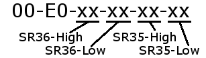
| %SR35-36 |
Unique Serial Number /
Hexadecimal l LAN1 MAC ID
|
|
Read Only | Read Only | |
| %SR37 | Model Number | Read Only | Read Only | ||
| %SR38 | Engine Version ( /100) |
|
|
Read Only | Read Only |
| %SR39 | BIOS Rev Number ( / 100) |
|
|
Read Only | Read Only |
| %SR40 | FPGA Image Rev Number ( / 10) |
|
|
Read Only | Read Only |
| %SR41 |
*Excludes RCC Units |
|
|
Read Only | Read Only |
| %SR42 |
*Excludes RCC Units |
|
|
Read Only | Read Only |
| %SR43 |
*Excludes RCC Units |
|
|
Read Only | Read Only |
| %SR43.1 |
System menu lock (SYS_DISABLE) 1 (high) = Restricts access to system menu 0 (low) = Allows access to system menu Note(s)
|
||||
| %SR44 | Real-Time-Clock Second | 0 to 59 | Read Only | Read Only | |
| %SR45 | Real-Time-Clock Minute | 0 to 59 | Read Only | Read Only | |
| %SR46 | Real-Time-Clock Hour | 0 to 23 | Read Only | Read Only | |
| %SR47 | Real-Time-Clock Date | 1 to 31 | Read Only | Read Only | |
| %SR48 | Real-Time-Clock Month | 1 to 12 | Read Only | Read Only | |
| %SR49 | Real-Time-Clock Year | 1996 to 2095 | Read Only | Read Only | |
| %SR50 | Real-Time-Clock Day (1=Sunday) |
RTC_DAY |
1 to 7 | Read Only | Read Only |
| %SR51 | Network Error Count | Read Only | Read Only | ||
| %SR52 | Watchdog-Tripped Error Count | Read Only | Read Only | ||
| %SR53-54 | Reserved | ||||
| %SR55.13 | Self-Test: Battery Low or Missing | Read Only | Read Only | ||
| %SR56 |
No key = 0 (No key pressed since power-up) F1 = 1 F2= 2 F3= 3 F4 = 4 F5= 5 F6= 6 F7=7 F8= 8 F9= 9 F10 = 10 F11= 11 F12 = 12 Enter = 13 +/ - = 14 . (dot) = 15 0 = 16 1 = 17 2 = 18 3 = 19 4 = 20 5 = 21 6 = 22 7= 23 8 = 24 9 = 25 System = 26 Escape = 27 Left = 28 Right = 29 Up = 30 Down = 31 Shift = 32 Soft Key 1 = 34 Soft Key 2 = 35 Soft Key 3 = 36 Soft Key 4 = 37 Soft Key 5 = 38 Soft Key 6 = 39 Soft Key 7 = 40 Soft Key 8 = 41 Release = 255 (Keys pressed since power- up but not currently) *Excludes RCC Units |
LAST_KEY | 0 to 255 | Read Only | Read Only |
| %SR57 |
0-100 = 0% to 100% On 100-255 = 100% On *Excludes RCC Units |
0 to 255 | Read Only | Read Only | |
| %SR57.16 |
Temporarily disable Screen Saver *Excludes RCC Units |
Read/Write |
Read/Write | ||
| %SR58 | User LEDs |
USER_LEDS |
|
Read/Write |
Read/Write |
| %SR59 |
(Only last three numbers displayed) |
|
|
Read Only | Read Only |
| %SR60 |
Build Test = 0 Build Beta = 1 Build Product = 2 |
0 to 2 | Read Only | Read Only | |
| %SR61 | Number of CsCAN |
NUM_IDS |
|
Read Only | Read Only |
| %SR62 |
This register can be used to run diagnostics on the Serial Port hardware and functionality. |
Read/Write | Read/Write | ||
| %SR63-100 | Reserved |
|
|
|
|
| %SR101.3 |
WebMI License Details – WebMI server status *XLEe, XLTe, X2, X4, X7 & X10 |
|
|
Read Only | Read Only |
| %SR101.4 |
WebMI License Details – WebMI user logged in status *XLEe, XLTe, X2, X4, X7 & X10 |
|
|
Read Only | Read Only |
| %SR101.8 - 101.16 |
WebMI License Details – Number of users *XLEe, XLTe, X2, X4, X7 & X10 |
|
|
Read Only | Read Only |
| %SR102 | Reserved |
|
|
|
|
|
-and- |
The following applies only to XL Prime models: RTC Battery Age
Note: Applies only to XL Prime models.
The following license registers are applicable to the XLE_Ee/XLT_Te/X2 only |
||||
|
%SR104-5 |
For security enabled PGM/Clone files enter password of current program running in the controller |
|
|
Read/Write |
Read/Write |
|
%SR106-7 |
For security enabled PGM/Clone files enter password of program file that to be loaded in the controller. |
|
|
Read/Write |
Read/Write |
|
WebMI License Details – Number of webpages *XLEe, XLTe, X2, X4, X7 & X10 |
|
|
Read Only | Read Only | |
| %SR109 | WebMI License Details – Number of datapoints
*XLEe, XLTe, X2, X4, X7 & X10 |
|
|
Read Only | Read Only |
| %SR110-112 |
WebMI License Details – Expiry date of WebMI license *XLEe, XLTe, X2, X4, X7 & X10 only |
|
|
Read Only | Read Only |
| %SR113-130 | Reserved |
|
|
|
|
| %SR131-135 | OCS Model: ASCII, 10 characters |
|
|
Read Only | Read Only |
| %SR136 | Communication Download Timeout |
|
|
Read Only | Read Only |
| %SR137 | Communication Idle Timeout |
|
|
Read Only | Read Only |
| %SR138-148 | Reserved |
|
|||
| %SR149-150 |
Free-running 10kHz count: 1 count = 0.1ms (32-Bit DINT) |
|
|
Read Only | Read Only |
| %SR151 | Reserved |
|
|
|
|
|
-and- |
Apply License Through System Menu - Control Registers
Note: Applies only to XL Prime |
||||
|
-and- |
Apply License Through System Menu - Status Registers
Note: Applies only to XL Prime |
||||
| %SR152 |
|
|
|
Read/Write |
Read/Write |
| %SR152.1 |
MJ2 Termination Enable for XLPlus only *Excludes RCC972 |
Read/Write |
Read/Write | ||
| %SR152.2 |
MJ3 Termination Enable for XLPlus only. *XL+ Only |
|
|
Read/Write |
Read/Write |
| %SR152.3 |
MJ1 Termination Enable for XLPlus only. RS RS-485 Termination Enable for X2, X4, X7 & X10 only |
|
|
Read/Write |
Read/Write |
| %SR152.4 |
CAN Termination Enable - *X4, X7 & X10 Only |
|
|
Read/Write |
Read/Write |
|
CANVAS Only Setting True saves the currently loaded program as PGM file in the Micro SD card as “DEFAULT.PGM”. |
|
|
Read/Write | Read/Write | |
|
CANVAS Only Setting True loads, the “DEFAULT.PGM” file located in Micro SD card. |
|
|
Read/Write | Read/Write | |
| %SR153 |
CAN Protocol Settings
|
Read/Write | Read/Write | ||
| %SR154 | Loading of Firmware
Note: Applies only to XL Prime and CANVAS |
||||
| %SR155-163 | Reserved |
|
|
|
|
| %SR164 | FailSafe / clone |
|
|
|
|
| %SR164.1 | RS485 Port Biasing #1 (MJ1 or MJ2) | Read/Write | Read/Write | ||
| %SR164.2 | RS485 Port Biasing #2 (MJ2 or MJ3) | Read/Write | Read/Write | ||
| %SR164.3 |
Indicates Automatic Restore Operation has been performed |
AUTO_RESTRD | Read Only | Read Only | |
| %SR164.4 | Indicates Backup of Registers has been taken | BCKUP_TAKN | Read Only | Read Only | |
| %SR164.5 | EN_AUTO_LD | Read/Write | Read/Write | ||
| %SR164.6 | EN_AUTO_LD | Read/Write | Read/Write | ||
| %SR164.7 |
Start Backup trigger bit – Setting TRUE starts backup of all register data |
STRT_BCKUP | Read/Write | Read/Write | |
| %SR164.8 |
Clear Backup trigger bit – Setting TRUE clears backup of all register data (if a backup was done previously) |
CLR_BACKUP | Read/Write | Read/Write | |
| %SR164.9 |
Setting TRUE does a Load Clone (if a media card is present) Note: Device displays appropriate errors if the MJ1 port was being used in the program settings or if any port is opened in the program while Make / Load Clone of the program is being done. |
MAKE_CLONE | Read/Write | Read/Write | |
| %SR164.10 |
Setting TRUE does a LOAD CLONE (if a media card is present that contains clone files) Note: Device displays appropriate errors if the MJ1 port was being used in the program settings or if any port is opened in the program while Make / Load Clone of the program is being done. |
LOAD_CLONE | Read/Write | Read/Write | |
| %SR164.11 |
(This bit goes high when Make/Create Clone / Save PGM fails) |
MK_CLN_FL | Read/Write | Read/Write | |
| %SR164.12 |
Load Clone Fail / Load PGM Fail (This big goes high when Load Clone / Load PGM fails) |
LD_CLN_FL | Read/Write | Read/Write | |
| %SR164.14 |
Set to 1 to restore data manually, and this in turn sets %SR164.15 to 1. Set to 0 to abort restore operation. *RCC Units Only |
|
|
Read/Write | Read/Write |
| %SR164.15 |
Set to 1 for manual restore of data. Set to 0 to complete the restore operation. *RCC Units Only |
|
|
Read/Write | Read/Write |
| %SR164.16 |
Setting to 1 initiates a manual Restore remotely. *Applicable to XLPrime, Canvas, Micro Series and XLE/Ee, XLT/Te models. Program and Display |
Read/Write | Read/Write | ||
| %SR165-166 | Reserved |
|
|
|
|
| %SR167 |
Screen Update Time, Default= 5 *X4, X7 & X10 Only – Default = 10 |
|
2 to 50 |
Read/Write | Read/Write |
| %SR168 |
Note: Applicable to XL Prime and Canvas models only |
|
|
|
|
| %SR169 |
Note: Applicable to XL Prime and Canvas models only |
||||
| %SR170 |
Note: Applicable to XL Prime and Canvas models only |
||||
| %SR171 | X-Coordinate Touched |
|
|
Read Only |
Read Only |
| %SR172 | Y-Coordinate Touched |
|
|
Read Only |
Read Only |
| %SR173 | System-Function Disable | 0 to 1 | Read/Write | Read/Write | |
| %SR174 | Removable Media Protect | Read/Write | Read/Write | ||
| %SR174.1 | Request Media Card be Removed | Read/Write | Read/Write | ||
| %SR174.2 | Indicates safe to remove Media Card | Read/Write | Read/Write | ||
| %SR175 | Removable Media - Status |
Read Only |
Read Only | ||
| %SR176-177 | Removable Media Free Space (32-Bit DINT) |
Read Only |
Read Only | ||
| %SR178-179 | Removable Media Total Space (32-Bit DINT) |
Read Only |
Read Only | ||
| %SR180 | Reserved | ||||
| %SR181 | ALM_UNACK |
Read Only |
Read Only | ||
| %SR182 | Bits 1-16 indicate Active in Alarm Groups 1-16 | ALM_ACT |
Read Only |
Read Only | |
| %SR183 |
0= Disabled 1= Enabled |
SYS_BEEP | 0 to 1 | Read/Write | Read/Write |
| %SR184 |
0=OFF 1=ON |
USER_BEEP | 0 to 1 | Read/Write | Read/Write |
| %SR185 |
0= Disabled 1= Enabled NOTE: See %SR57.16 |
0 to 1 |
Read Only |
Read Only | |
| %SR186 | Screen Saver Time in minutes (delay) | 5 to 1200 |
Read Only |
Read Only | |
| %SR187 | Network Usage (Avg) | NET_USE | 0 to 1000 |
Read Only |
Read Only |
| %SR188 | Network Usage (Min) | 0 to 1000 |
Read Only |
Read Only | |
| %SR189 | Maximum Net Usage of all units on the CAN network | 0 to 1000 |
Read Only |
Read Only | |
| %SR190 | Network TX Usage % ( / 10) (Avg) | NT_TX_AVG | 0 to 1000 |
Read Only |
Read Only |
| %SR191 | Network TX Usage % ( / 10) (Min) |
|
0 to 1000 |
Read Only |
Read Only |
| %SR192 | Network TX Usage % ( / 10) (Max) |
|
0 to 1000 |
Read Only |
Read Only |
| EXTENDED SYSTEM REGISTERS | |||||
| %SR193 | Online Change |
|
|
||
| %SR193.1 | TRUE if 2 programs in target FLASH |
Read Only |
Read Only | ||
| %SR193.2 | TRUE to switch programs, FALSE when complete |
Read Only |
Read Only | ||
| %SR193.3 | TRUE if executing program is temporary test |
Read Only |
Read Only | ||
| %SR193.4 | TRUE during last scan of switched-from program |
Read Only |
Read Only | ||
| %SR193.5 | TRUE during first scan of switched-to program |
Read Only |
Read Only | ||
| %SR193.6 |
Read Only |
Read Only | |||
| %SR193.9 | TRUE if error in temporary program |
Read Only |
Read Only | ||
| %SR194 |
Battery Charge Temp Low – XLPrime series models XLPlus Models – CPU Frequency in MHz |
Read Only |
Read Only | ||
| %SR195 |
Battery Charge Temp High – XLPrime series models XLPlus Models – CPU temperature in degree centigrade |
Read Only |
Read Only | ||
| %SR196 |
NOTE: Refer to MAN1142 for more details on Rechargeable Batteries
0=Waiting 1=Normal Charging 2=Hot Charge 3=Hot Charge 4= Battery Hot 5= Cold Charge 6=Battery Cold 7=No Battery 8= Not Charging (after 8 hours of charging) 9= CPU Hot, not charging 10 Battery voltage <2V, not charging 11= First 2 minutes Init Wait (Not Charging) |
0 to 11 |
Read Only |
Read Only | |
| %SR197 | Charging Current Max mA |
Read Only |
Read Only | ||
| %SR198 | Battery Voltage is mV |
Read Only |
Read Only | ||
| %SR199 | Reserved | ||||
| %SR200 | InitRD Version ( /100) |
Read Only |
Read Only | ||
| %SR201 - 205 | Linux Kernel version: ASCII, 10 characters |
Read Only |
Read Only | ||
| %SR206-208 | Reserved | ||||
| %SR209.3 | WebMI Server Status. Bit 3 is ON if server running. |
Read Only |
Read Only | ||
| %SR209.4 |
Bit 4 is ON if 1 or more users logged in. |
Read Only |
Read Only | ||
| %SR209.8 - 209.14 |
Shows in upper byte in decimal format. |
Read Only |
Read Only | ||
| %SR210 |
Time Zone: set in minutes + / - UTC (Ex: EST is -4 hours = -240 minutes) |
Read/Write | Read/Write | ||
| %SR211 |
Daylight Saving: NO = 0 (If daylight saving is enabled, one hour will be added to the local time). |
Read/Write | Read/Write | ||
| %SR212 | UTC |
Read Only |
Read Only | ||
| %SR213 | UTC - Minutes |
Read Only |
Read Only | ||
| %SR214 | UTC - Hours |
Read Only |
Read Only | ||
| %SR215 | UTC - Date |
Read Only |
Read Only | ||
| %SR216 | UTC - Month |
Read Only |
Read Only | ||
| %SR217 | UTC - Year |
Read Only |
Read Only | ||
| %SR218 |
Number of Webpages, license detail (XLE/XLT, X2, X4, X7 & X10 use %SR101 & %SR108-112 for WebMI License Details.) |
Read Only |
Read Only | ||
| %SR219 |
Number of Data Points, license detail. (XLE/XLT, X2, X4, X7 & X10 use %SR101 & %SR108-112 for WebMI License Details) |
Read Only |
Read Only | ||
| %SR220-222 |
Expiration Date of WebMI License, license detail. (XLE/XLT, X2, X4, X7 & X10 use %SR101 & %SR108-112 for WebMI License Details) |
Read Only |
Read Only | ||
| %SR223.7 |
In case of asynchronous caching, it is instant. This is applicable for Canvas models only. |
||||
|
DHCP1 0= Disabled 1= Enabled |
|||||
| SR235.2 |
DHCP2 0= Disabled 1= Enabled |
||||
| %SR265 | |||||
| %SR266 | Wi-Fi Connection Mode | ||||
| %SR267-275 | Wi-Fi MAC ID | ||||
| %SR276-291 | Wi-Fi AP Mode Name | ||||
| %SR292-307 | Wi-Fi AP Mode Password | ||||
| %SR308 | Wi-Fi AP Mode Encryption | ||||
| %SR309-310 | Wi-Fi AP Mode IP | ||||
| %SR311 | Wi-Fi AP Mode Channel | ||||
| %SR312-327 | Wi-Fi ST Mode Name | ||||
| %SR328-343 | Wi-Fi ST Mode Password | ||||
| %SR345 | Wi-Fi Auto Connect Enable | ||||
| %SR346 | Wi-Fi ST Status | ||||
| %SR347-348 | Wi-Fi ST Mode IP | ||||
| %SR349 | Wi-Fi ST Signal Health | ||||
| %SR349 | |||||
For I/O Register Maps for individual controllers, refer to the Horner website Document Search page.
Return to the Top: System Register Tables