Connection Wizard 
See also: Tools and Help in Cscape
Topic Menu
Connection Wizard Overview
By default, the Connection Wizard displays each time Cscape is opened. This can be disabled or re-enabled by unchecking or checking the "Show connection wizard on startup" in the lower left-hand corner of the Connection Wizard.
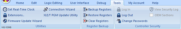
Connection Wizard can be accessed through Tools > Utilities > Connection Wizard.
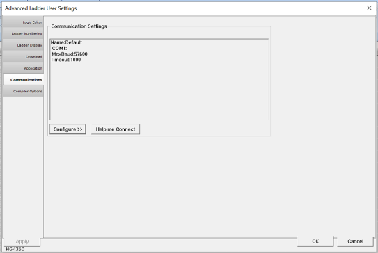
The Connection Wizard can also be accessed through the User Settings: System > Settings > User Settings > Communications > Help me Connect
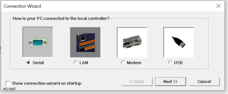
Once selected, the user will have the open on connection types:
Return to the Top: Connection Wizard
Connection through Serial Ports
Select the Serial button and select Next>>, the following window opens:
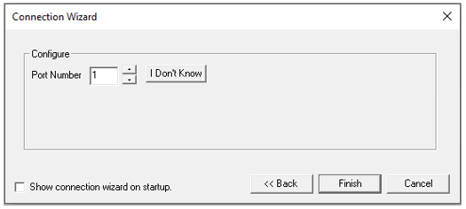
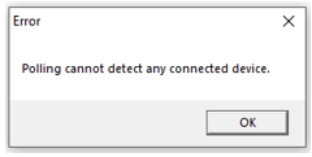
If the COM port number of the connected device is not known, select I Don't Know button. The program searches and displays COM port number of the detected device. If no device detected, then the following message is displayed:
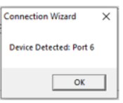
After the COM port number is detected, this window appears with the port#:
By clicking on OK, then Finish connects the application to the detected device.
Return to the Top: Connection Wizard
Connection through Ethernet
See also: Ethernet Configuration Overview
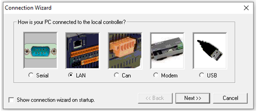
Select LAN and select Next>> to open the following dialog:
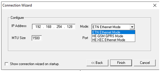
IP Address![]() IP Address - Internet Protocol - This is the address of a device on an Ethernet or Wi-Fi network. Horner controllers currently use IPv4 standards with addresses consisting of 4 numbers, or octets, separated by decimal points.: Enter the IP address of the device. This may be the OCS itself or a router/firewall behind which the OCS is connected on a subnet.
IP Address - Internet Protocol - This is the address of a device on an Ethernet or Wi-Fi network. Horner controllers currently use IPv4 standards with addresses consisting of 4 numbers, or octets, separated by decimal points.: Enter the IP address of the device. This may be the OCS itself or a router/firewall behind which the OCS is connected on a subnet.
Mode:Depending on the OCS Ethernet connection, select the appropriate mode as follows:
-
Built in / ETN Ethernet Mode:Select this option if the device has on-board Ethernet port.
-
HE – GSM GPRS Mode: Select this option if communication with XL series controller on GPRS is required and the device has GSM modem installed in XL series controller.
NOTE: For GPRS connectivity, GPRS configuration from Home > Messaging > GPRS needs to be done.
-
HE – XEC Ethernet Mode: Select this option if the device has Ethernet comm. option board installed in XL series controller.
MTU Size: This indicates the packet size that is transferred at once over an Eethernet network. Default is 1500, which is the maximum setting and is commonly used. Consult IT personnel for an MTU size that should work on the network to which the OCS is connected. and IT personnel should know what to use if 1500 doesn't work.
Port:The CsCAN Protocol normally uses Port 18501 and all OCS devices use this port without the ability to change it. When connecting through a router/firewall, the port forwarding functions of the router/firewall may be used to route a different port number specified here to the IP address and port 18501 of the OCS on the subnet behind the router/firewall. This allows access to connect to multiple OCS devices behind a single IP address.
After configuring, click Finish.
Return to the Top: Connection Wizard
Connecting through CAN
See CANopen Guide for more details.
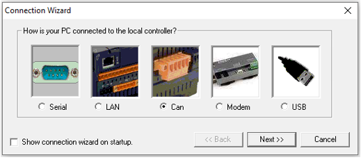
Select CAN and select Next>>, the following window opens:
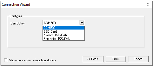
Select the CAN Option from the drop-down menu. NOTE: Entries on this drop-down menu must be installed/plugged into the PC.
After making a selection, click Finish.
Connecting through a Modem
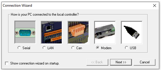
Select Modem and select Next>>, the following window opens:
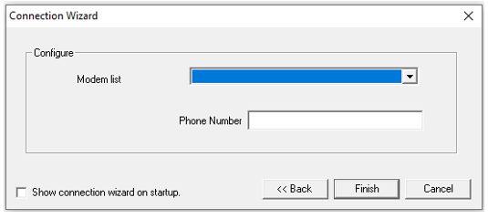
Select the modem from the list available and enter the phone number.
After configuring, click Finish.
Return to the Top: Connection Wizard
Connecting through USB
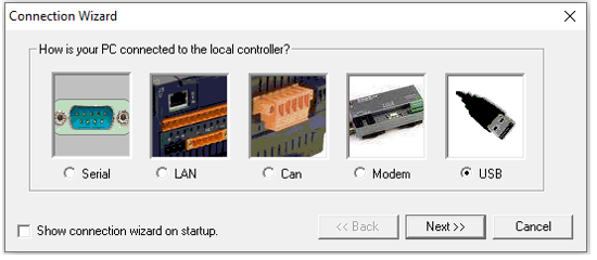
Select USB and click Next>>, the following window opens:
NOTE: If attached devices are not shown in this dropdown, it indicates that those devices are not recognized properly by the Windows operating system. The drivers need to be fully installed or updated using the Windows Device Manager. Once properly installed, OCS devices will display as "Controller USB Com Port" or similar. Newly attached or updated devices will not refresh in this dropdown until exiting this window and reopening.
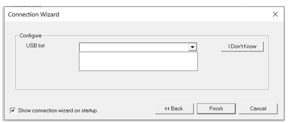
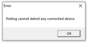
If the COM port number of the connected device is not known, then click the I Don't Know button. Cscape will search and display the COM port number of the detected device. If no device is detected, then Cscape shows appropriate message to the user.
The program searches & displays COM port number of the detected device. If no device detected, then the following message is displayed:
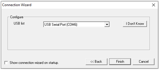
After COM port number is detected, this window appears with the port# detected:
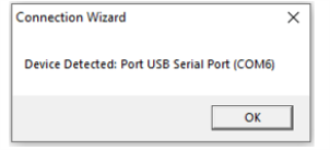
Click OK then Finish connects the application to the detected device.
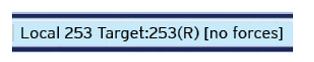
NOTE:The communication medium and connection status will be indicated on the Cscape Status Bar.
One indicator of a successful connection is the Local/Target area showing both a Local ID and a Target ID, along with the status of the Target controller (shown here as (R) for "In RUN mode" and [no forces] indicating that no I/O is being forced). Another indicator of a successful connection is the absence of question marks anywhere in the Local/Target portion of the status bar.

Return to the Top: Connection Wizard
Connection Issues - Troubleshooting
Connecting to the Controller
Cscape connects to the local controller automatically when the connection is made. The status bar below shows an example of a successful connection. This status bar is located in the bottom right-hand corner of the Cscape window.
In general, the Target number should match the Local number. The exception to this is when the controller is being used as a "pass through" unit where other controllers on a CsCAN![]() Horner APG's proprietary network protocol that runs on the Bosch CAN network specifications. Prior to the advent of the OCS. network could be accessed through the local controller. Determine connection status by examining feedback next to Local and Target in the status bar of Cscape.
Horner APG's proprietary network protocol that runs on the Bosch CAN network specifications. Prior to the advent of the OCS. network could be accessed through the local controller. Determine connection status by examining feedback next to Local and Target in the status bar of Cscape.
See also: Cscape Status Bar
Cscape Target and Local Numbers
|
Local / Target |
Description |
Action |
|---|---|---|
|
Local: ### |
A number to the right of “Local” indicates that coms are established to the local controller. |
No action required |
|
Local: No Port |
Cscape is unable to access the PC COM port. |
Check Device Manager to ensure that Cscape is set to a valid COM port. Ensure that no other programs are utilizing the same COM port, including other instances of Cscape or EnvisionRV. |
|
Local: No Com |
Cscape has accessed a PC COM port but is not communicating with the controller. |
Check cable connections. Check for correct default programming port on the controller. If connecting via Ethernet, check IP address. |
|
Local: ??? |
Unknown communication error. |
Close Cscape, power cycle the controller and reopen Cscape with a blank project. |
|
Local: Disconnect |
When using USB to serial adapter; configured comport number is incorrect or USB adapter has malfunctioned. |
Check the COM port number. Check USB to serial adapter or try a different USB to serial adapter. |
|
Local: Busy |
Could indicate that two instances of Cscape / Envision RV are open. Can be caused by high CsCAN network traffic on the primary CAN port. |
Ensure that only one instance of Cscape or EnvisionRV is open. If CsCAN traffic is suspect, place controller(s) on the network in IDLE/STOP mode. |
|
Target: # (I, R, D) |
If I (idle), R (run), or D (do I/O) shows next to Target number then communication is established to the target controller. |
No Action Required |
|
Target: #(?) |
Communication is not established to the target controller. |
Check node ID Make sure local connection is established. |
Connecting Troubleshooting Checklists
Serial port – MJ1/2/3 Programming
-
Controller must be powered up.
-
Use the Connection Wizard to ensure the correct COM port is selected in Cscape.
-
Check the System Menu to verify which MJ port is configured as the default programming port. (System Menu > Set Serial Ports > Dflt Pgm Port)
-
Ensure that the proper controller cables and pin-outs are being used between the PC and the controller MJ port.
-
Check that a Loaded Protocol or ladder open function is not actively using the MJ programming port. Taking the controller out of Run Mode from the System Menu on the controller will make the MJ port available to Cscape.
-
Successful communications with USB-to-serial adapters vary. If in doubt, Horner APG offers a USB to serial adapter. For Cscape with symbols AND the programming cables, refer to the HE-CPK. For the programming cables only, refer to HE-XCK.
-
In Windows Device Manger > Ports (COM & LPT) on PC, the Horner Programming cable, HE-XCK or HE-CPK, should appear as: “USB Serial Port (COM#)”.
-
Drivers can be downloaded from the Horner Support Files page, scroll to the bottom of the page to find the Communication Drivers.
USB Port - Mini B Programming
-
Controller must be powered up.
-
Ensure that the correct COM port is selected in Cscape. Use the [Connection Wizard] to ensure the correct COM port is selected in Cscape.
-
Ensure that the USB cable is connected between the PC and controller. Check Windows Device Manager to verify port number and proper installation of USB driver. Device manage > Port (COM & LPT) > Controller USB Com Port (COM#)
-
The USB driver for the Mini-B programming port installs with Cscape. In some cases, it may be required to take an additional step of updating the driver inside of Windows Device Manager. If that is the case, the PC should be connected to the Internet and select the option to allow Windows to search for the driver.
-
Drivers can be downloaded from the Horner Support Files page, scroll to the bottom of the page to find the Communication Drivers.
ETN port programming
Refer to Ethernet Configuration Overview
Local Controller and Local I/O
The System Menu on the controller provides the following status indications that are useful for troubleshooting and system maintenance. Refer to the User Manual for details for specific controllers. See the Horner Documentation Search Page: https://hornerautomation.com/documentation-search/
-
Self-test results, diagnostics.
-
RUN and OK status
-
Network status and usage
-
Average logic scan rate
-
Application memory usage
-
Loaded firmware versions
-
Loaded protocols
-
Removable media access
Local I/O Troubleshooting Checklist
-
Verify the controller is in RUN mode.
-
Check diagnostics to ensure controller passed self-tests. View Diags in System Menu or in Cscape, select Debug > Debug > Diagnostics
-
Check datasheet to ensure proper wiring.
-
Ensure that hardware jumpers and software configuration for I/O match.
-
Check datasheets for voltage and current limits.
-
Take ladder out of the picture. From Cscape set controller to “Do I/O” mode. In this mode inputs can be monitored, and outputs set from a data watch window in Cscape without interference from the ladder program. Some I/O problems are only a result of a mistake in the ladder program.
WARNING: Setting outputs ON in Do I/O mode can result in injury or cause machinery to engage in an unsafe manner depending on the application and the environment.
CsCAN Network
For complete information on setting up a CsCAN network, refer to [CAN Networks manual].
Network status, node ID, errors, and baud rate in the controller System Menu are all in reference to the CsCAN network. These indications can provide performance feedback on the CsCAN network and can also be used to aid in troubleshooting.
CsCAN Network Troubleshooting Checklist
-
Use the proper Belden wire type or equivalent for the network as specified in MAN0799.
-
The controller does not provide 24VDC to the network. An external voltage source must be used for other devices such as SmartStix I/O.
-
Check voltage at both ends of the network to ensure that voltage meets specifications of attached devices.
-
Proper termination
 A load connected to the end of a transmission line. To avoid signal reflections, it must match the characteristic impedance of the line. is required. Use 121Ω (or 120Ω) resistors at each end of the network. The resistors should be placed across the CAN_HI and CAN_LO terminals.
 -
Measure the resistance between CAN_HI and CAN_LO. If the network is properly wired and terminated, there should be around 60Ω.
-
Check for duplicate node ID
Usually refers to the ID of the device on a supported CAN, such as CsCAN, CANopen, etc. Each device must have a unique network ID. Also called Node ID.’s. -
Keep proper wires together. One twisted pair is for V+ and V- and the other twisted pair is used for CAN_HI and CAN_LO.
-
Make sure the baud rate is the same for all controllers on the network.
-
Assure shields are connected at one end of each segment – they are not continuous through the network.
-
Do not exceed the maximum length determined by the baud rate and cable type.
-
Total drop length for each drop should not exceed 6m (20’). A drop may include more than one node. The drop length adds to the overall network length.
-
Network should be wired in "straight line" fashion, not in a "star" pattern.
-
In applications requiring multiple power supplies, make sure the V- of all supplies is connected and to earth ground at one place only.
-
In some electrically noisy environments, it may be necessary to add repeaters
A device that amplifies or adds to incoming electrical signals and retransmits them, in order to compensate for transmission losses. Repeaters can be used to add additional nodes and/or distance to the network and protect the signal against noisy environments. to the network. Repeaters can be used to add additional nodes and/or distance to the network and protect the signal against noisy environments.
Return to the Top: Connection Wizard