SMS Communications 
See also: Networking and Communications
Topic Menu
SMS Overview

|
Energy Monitoring Application: Cscape Example |
SMS (Short Message Service) is a type of communications process that enables the transmission of short text messages / data transfers to and from mobile devices such as cell phones. Messages are usually limited to 140 -160 characters in length and are stored and forwarded at SMS centers. This allows messages / data transfers to be retrieved immediately or at a later time via an SMS center.
SMS communications provide an affordable and convenient means to send and receive text messages /data transfers using mobile devices such as cell phones. Businesses and industry often require 24-hour coverage of their operations and have personnel who are on-call after normal work hours to handle work-related issues and emergencies. There are employees who are responsible for the proper functioning of equipment and processes at remote sites. Managers need to be notified of significant events.
Using SMS Communications with Horner Controllers
The SMS feature in selected Horner controllers provides the capability of sending and receiving text messages and register data values using mobile devices such as a cell phone. Depending upon the configuration, approved group members can read and write values into the controller's data registers. This kind of communication is referred to as a data transfer.
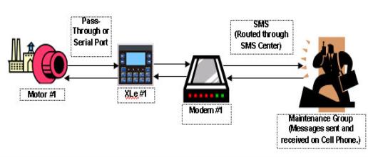
Follow the sequence of events described below.
-
Motor #1 stops. Data is sent to a register in the controller.
-
The XLE reads the data register value indicating Motor #1 has stopped. The XLE sends a message through a modem to the cell phone of a Maintenance Group member via SMS Communications. Transmissions are routed through an SMS center.
-
The Maintenance Group member receives the following message on a cell phone: Motor #1 speed is 0.
-
The Maintenance Group member sends the following message back to the XLE using a cell phone via SMS communications: Motor #1 Start Speed is 1800. Again, the transmissions are routed through an SMS center.
-
The XLE reads the register containing the data value sent from the Maintenance Group member and responds as programmed. The XLE sends a signal to start Motor #1.
-
Motor #1 re-starts, and normal operation is restored.
Requirements for SMS Communications
Assuming the controller used has the SMS feature, the user needs to configure the controller using Cscape software for SMS communications. In addition, the mobile devices that send and receive messages (For example - cell phones) need to have SMS capabilities, and the users must have a service that provides SMS communications.
As part of the SMS configuration, a list of approved phone numbers and authorized messages that will be used for SMS communications must be provided. Because the SMS feature allows the users to read and write to controller registers, it is important to follow good standard security practices to safeguard systems. Whether the users are allowed to write to registers or not, ensure that security is in place to protect against unauthorized inputs to registers.
Return to the Top: SMS Communications
SMS Configuration
See also: GSM Configuration
Cscape software is used to configure the necessary attributes in selected Horner controllers to send and receive short text messages and data transfers using SMS communications. After the SMS configuration is completed and downloaded into the controller, approved group members can send and receive a variety of information such as register values and emergency alerts using cell phones and other mobile devices. NOTE : Maximum numbers of SMS (RX + TX) messages supported by Horner firmware are 128. i.e. the user can configure 64 TX and 64 RX or say 100 TX and 28 RX or vice versa.
Step 1. Select the desired controller. See: Hardware Configure for more details.
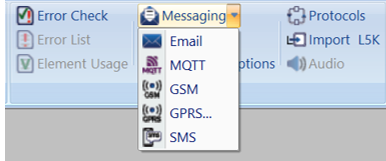
Step 2. Select Home > Program > Messaging > SMS
Step 3. The following dialog will appear:
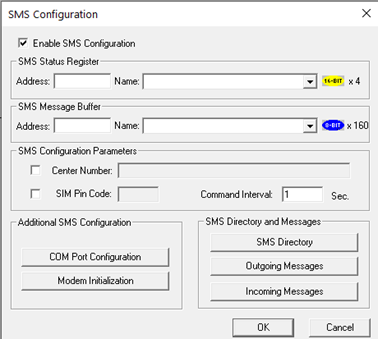
Step 4. Select Enable SMS Configuration checkbox to begin SMS configuration.
Step 5. The SMS Configuration has several sections that require configuration.
a. SMS Status Register Configuration
Status Registers Settings |
|
|
Address |
Enter the starting register location to indicate the status of the SMS communication. This is a block of four registers that are consecutive in memory. For example, if the users are using R31– R34, then the users need to enter the starting register address as %R0031. |
|
Name |
Enter (or select) an I/O Name. |
The Status Register contains a status bit indicating the condition of the SMS communication. The following table contains the meaning of each status bit.
b. SMS Message Buffer Configuration - The Message Buffer Register holds the latest SMS message string sent or received by the controller. An individual SMS message can have up to 160 characters.
c. SMS Configuration Parameters
Configuration Parameters |
|
|
Center Number |
If required, select the box and type in Center number (up to 16 digits). The Center Number uses numbers 0 – 9 and these special characters: , ( ) – + |
|
SIM Pin Code |
If required, select the box and type Pin number (up to 4 digits). SIM Pin Code can have only digits 0 – 9. |
|
Command Interval |
This is the interval of time (in seconds) that the OCS poll for messages (valid range: 1 - 100). |
d. Additional SMS Configuration - Be sure to click each button and perform the configuration procedures associated with each button.
Return to the Top: SMS Communications
Modem Initialization
Open the SMS Configuration dialog from Home > Program > Messaging > SMS
Step 1: Click Enable SMS Configuration button
Step 2: Select Modem Initialization button to open dialog below:
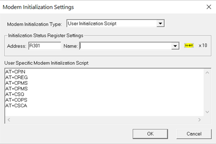
Configuration of Initialization Status Register Settings and User Specific Modem Initialization Script in the above screen is required when User Initialization Script is selected.
|
Modem Initialization Type |
The following options are available: No Initialization (Modem Preconfigured): No initialization of GSM modem will be done. Select this option if connected GSM modem is pre-configured and does not require initialization. Internal Modem Initialization: Select this option if there is an XLT with internal modem. Siemens TC Modem Initialization: In case of external GSM modem, select this option. User Initialization Script: To use own initialization script, select User Initialization Script. When User Initialization Script is selected, it is necessary to configure initialization status register and provide initialization script.
The type of Modem Initialization used affects various settings that are available on the COM Port screen. |
|
Address |
Enter the starting register address location used to store the additional modem initialization script’s latest command executed. This is a block of 10 registers that are consecutive in memory. For example, if the users are using R301 - R310, then the users need to enter the starting register address as %R301. |
|
Name |
Enter (or select) the I/O Name. |
|
User Specific Modem Initialization Script |
Enter script in this box. |
NOTE: Firmware will send fixed standard AT commands to the external modem through serial port.
Return to the Top: SMS Communications
COM Port Configuration
Open the SMS Configuration dialog from Home > Program > Messaging > SMS
Step 1: Click Enable SMS Configuration button
Step 2: Select Enable SMS Configuration button to open. NOTE: Before configuring this screen, the user needs to configure the Modem Initialization Settings screen. The type of Modem Initialization used affects various settings that are available on the COM Port screen such as the Port, Baud Rate, and Mode. After configuring the Modem Initialization Settings, configure the port to be used for communications. The following screen appears.
The following selections must match the default settings of the modem that is being used.
|
COM Port Configuration Settings |
|
|
Port |
Select the desired port. The number of ports vary depending on the controller used. For XLE internal modem, MJ1 should be selected. |
|
Mode |
Select connection mode. The drop-down list changes according to the port selection. For XLE internal modem, this selection should be GSM QUAD. For external GSM modem, RS-232 should be selected. |
|
Comm Settings |
Select Baud Rate, Parity, Data Bits, Stop
Bits and Handshake as per the default settings of the modem that is being used. |
Return to the Top: SMS Communications
SMS Target Directory Settings
How to set up the directory and send and receive messages.
Open the SME Target Directory through Home > Program > Messaging > SMS
Before creating Send or Receive messages, a directory of phone numbers needs to be created. Configure the following screen to build a directory.
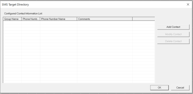
-
Click Add Contact to add a member. See the following screen (New Contact Information).
-
Click Modify Contactif a member is already added in the directory. (The User will see information about the members on the above screen.) To modify the member listing, either double-click the row or highlight the row and click Modify Contact. The Modify Contact Information screen appears, and it is configured like the New Contact Information screen shown below.
-
Click Delete Contactto remove a listing after highlighting the row.
|
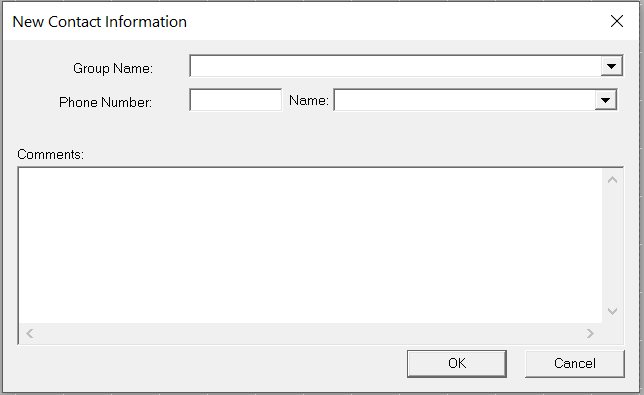
New Contact Information |
|
|
Group Name |
Enter or select a Group Name. 1. It can contain characters A-Z, a-z, 0-9, and the _ underscore character. 2. The first character must be A-Z, a-z, or the _ underscore character. 3. Do not use spaces or special characters. 4. Do not use two consecutive underscore characters.
|
|
Phone Number |
Either enter a phone number or enter a register where the phone number is stored.
|
|
Phone Number Name |
If the user specify a register address in the Phone Number field, the user can give the phone number an I/O name. |
|
Comments |
Add details for clarification. |
Click Modify Contact and Delete Contact buttons as needed.
Click OK to see the contacts on the directory.
The following screen shows examples of contacts added to the directory.
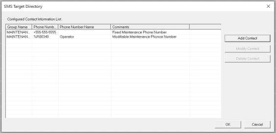
With the directory being created, the users are ready now to begin creating send and receive messages.
NOTES:
1. User can add maximum of 32 contacts in the Directory list.
2. If user is configuring the contacts using registers then user must take care that there is a gap of 12 registers between any two contact registers.
For example:- Contact 1 - %R1, Contact 2 - %R12 & so on.
Return to the Top: SMS Communications
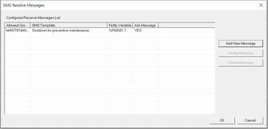
Incoming Messages Settings (RECEIVE)
Messages Sent from Groups to Controller
Before creating send or receive messages, a directory needs to be created, see above. After the directory is created, configure the following screen.
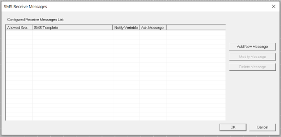
-
Click Add New Message to add a new message.
-
Click Modify Message to edit a message that is already on the list. Either double-click the row or highlight the row and click Modify Message.
-
Click Delete Message to remove a message after highlighting the row.
The following screen appears:
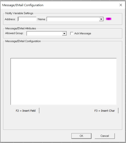
|
SMS Message Configuration |
|
|
Trigger Variable Settings |
Enter a bit reference in the Address field that will be set to high by the system when a valid SMS message associated with the trigger is received from the specified Group member. I/O name can be entered or selected in the Name field. |
|
Message Attributes |
Enter or select the group that can send an SMS message to the controller. Select the Ack Message check box if the user wants to send an acknowledgment to the user that the controller has received the message. |
|
Message Configuration |
Messages can contain text and register data values that approved group members can read and write into the controller's data registers at runtime. See Rules for Send and Receive Messages.
|

|
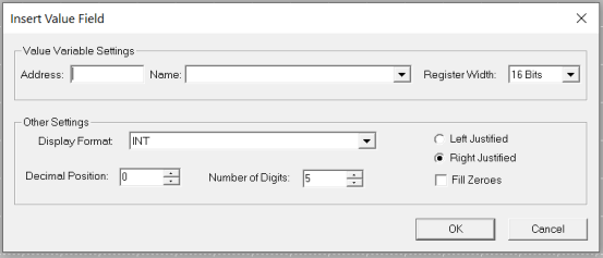
Insert Value Field |
|
|
Value Variable Settings |
Enter a register reference where data embedded in the received message will be stored. Select Register Width. |
|
Other Settings |
Select or enter the data type in the Display Format field. In the Decimal Position field, click the position of the decimal point. Click the number of digits in the Number of Digits. For example: xxxxx shows that there is no decimal and the total number of digits is 5.
If there had been a decimal point in the example, the decimal would have counted as one digit and would be included as part of the total number of digits.
Click the Fill Zeroes box and the Left Justified or Right Justified box if desired. |
Clicking OK returns to the SMS Configuration screen. If satisfied with the message, click OK. The following screen appears.
Rules for SMS Send and Receive Messages
-
Up to 160 characters can be used in each SMS Message.
-
Up to 20 data register value fields can be included in each message.
-
When the SMS Configuration dialog is closed, if a send message or receive message is found to have been associated with a non-existing contact information group, then the user will be notified about the error and provided with an opportunity to fix the same.
-
When adding contact in SMS directory through registers, the user should take care of providing proper phone number and the register should be a non zero value during run time. If the register is a zero value then OCS receives SMS from any phone number.
Return to the Top: SMS Communications
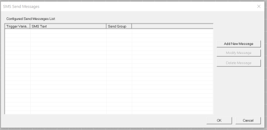
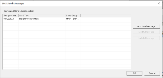
Outgoing Messages Settings (SEND)
Messages Sent from the Control to Groups
Note: Before creating send or receive messages, a directory needs to be created, see above. After the directory is created, configure the following screen:
-
Click Add New Message to add a new message.
-
Click Modify Message to edit a message that is already on the list. Either double-click the row or highlight the row and click Modify Message.
-
Click Delete Message to remove a message after highlighting the row.
When Add/Modify Message is clicked, the following screen appears.
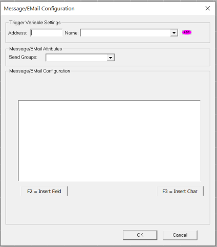
|
SMS Message Configuration |
|
|
Trigger Variable Settings |
An event is needed to trigger an SMS communication from the controller to the member(s) of a Group. Enter a bit reference in the Address field that (when set to HIGH) causes the SMS message associated with the trigger to be sent to the specified Group member(s). An I/O name can be entered or selected in the Name field. |
|
Message Attributes |
Enter or select the group that the SMS message is sent to. |
|
Message Configuration |
Messages can contain text and register data values that approved group members can read and write into the controller's data registers at runtime. See Rules for Send and Receive Messages.
|
|
Insert Value Field |
|
|
Value Variable Settings |
Enter a register reference where the data embedded in the message to send will be stored. An I/O name can be entered or selected in the Name field. Select Register Width. |
|
Other Settings |
Select or enter the data type in the Display Format field. In the Decimal Position field, click the position of the decimal point. Click the number of digits in the Number of Digits. For example: xx.xx shows that the decimal is in the 3rd position and the total number of digits (including the decimal) is 5.
Click the Fill Zeroes box and the Left Justified or Right Justified box if desired. |
Clicking OK returns to the SMS Configuration screen. If satisfied with the message, Click OK. The following screen appears:
Rules for SMS Send and Receive Messages
-
Up to 160 characters can be used in each SMS Message.
-
Up to 20 data register value fields can be included in each message.
-
When the SMS Configuration dialog is closed, if a send message or receive message is found to have been associated with a non-existing contact information group, then the user will be notified about the error and provided with an opportunity to fix the same.
Return to the Top: SMS Communications