GSM Configuration 
See also: Networking and Communications
Topic Menu
GSM Overview
Home > Program > GSM
LEGACY NOTICE: GSM Modem Option is NO LONGER supported by Horner APG.
GSM is a network used for connecting two devices and exchanging data. It can be used by OCS with internal GSM modem to communicate to another device connecting to Internet/ GSM/ PSTN network. For installing GSM modem option card in XL Series OCS, open the back cover of XL Series and connect Modem HE-GSM04A (no longer available) and then connect Antenna to modem.
With the GSM modem option card, the Data Exchange and Connectivity with Cscape can be established in the following two ways:
-
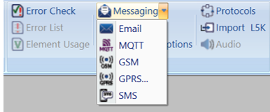
GSM connectivity
-
GPRS connectivity
NOTE: Cscape configuration for them is explained in the following sections.
-
GSM (Global System for Mobile) Functionality
-
GSM data call can be used for:
-
Peer-to-peer communication between two devices for exchanging register data.
-
Connect to Cscape for downloading/uploading and debugging the application
-
Send / receive configured SMS messages.
-
-
GSM data call connects at 9600bps only.
-
GSM data call requires ’data call enabled SIM’
Return to the Top: GSM Configuration
GSM Configuration
For Data exchange:
-
Horner OCS firmware is designed to initialize GSM modem to establish GSM data call.
-
In order to establish GSM data call connectivity using Horner OCS, complete the following.
Select GSM to open the GSM Configuration:
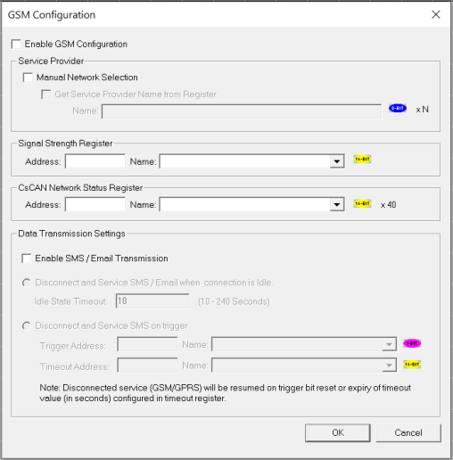
Select Enable GSM Configuration checkbox for GSM Configuration. The GSM Modem gets connected to the service provider automatically. In case selection of service provider needs to be done manually, Manual Network selection can be checked. The network provider name can be directly given in Address or the same can be provided through a register reference as well. To provide register reference for service Provider, check Get Service Provider Name from Register and enter the register reference in Address. In this case, the preferred service provider name string with null termination![]() Null Termination - To place a NULL character (character code 0) at the end of ASCII data. Some functions require NULL Termination to be able to determine the end point of the ASCII data since that data may vary in length from one time to the next. needs to be provided at the specified register. Configure a Register Address to store signal strength (Optional). Configure Status Register for CsCAN
Null Termination - To place a NULL character (character code 0) at the end of ASCII data. Some functions require NULL Termination to be able to determine the end point of the ASCII data since that data may vary in length from one time to the next. needs to be provided at the specified register. Configure a Register Address to store signal strength (Optional). Configure Status Register for CsCAN![]() Horner APG's proprietary network protocol that runs on the Bosch CAN network specifications. Prior to the advent of the OCS. communication (Optional).
Horner APG's proprietary network protocol that runs on the Bosch CAN network specifications. Prior to the advent of the OCS. communication (Optional).
For Connectivity with Cscape
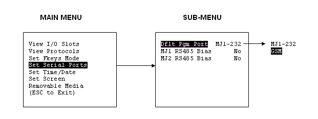
On the device, change the default programming port to GSM from the system menu, serial port option.
i.e. OCS ’system menu > Set Serial Ports > Dflt Pgm Port >GSM’ for MJ1.
NOTE: The Status of the connection will be updated in CsCAN Status Register in configuration windows. See Modem Status Register Value Definitions
Return to the Top: GSM Configuration
GSM Communication Blocks
Open Port
For peer to peer communication over GSM/GPRS, communication blocks are required to be configured as follows: Project Toolbox > Serial Operations > Open Serial Port. Follow the above steps will create an Open Port, also called a Function Block. Drag it to the grid.
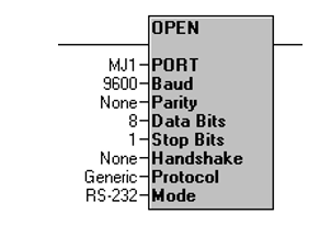
Double click function block, and the following dialog box appears:
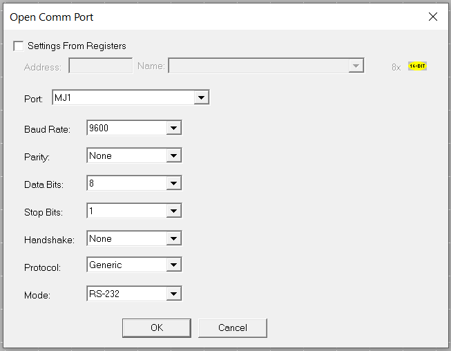
In case of internal GSM modem, the mode should be specified GSM Quad. Follow the configuration shown above. The protocol can be selected from the drop down as CsCAN, Generic or Modbus. For Modbus, Slave or Master block should be used.
Return to the Top: GSM Configuration
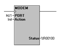
Modem Control Block
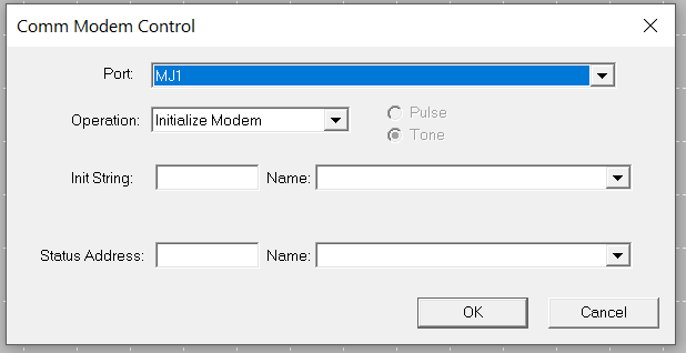
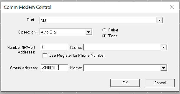
NOTE: To use modem control block, the comm port must be opened first using Open Port block.
Auto Dial Modem Option
GSM Data Call
-
Modem Control block with ’Auto Dial’ option is used for calling remote device (server)
-
Remote device data number must be entered in ’Number’ text box.
-
Select type of dialing as Tone
-
Configure the status register to show the status of the connection. See Modem Status Register Value Definitions

Double click on the function block, and the following dialog box appears:
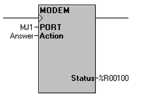
Auto Answer Modem Option - GSM Data Call
Modem Control block with ’Auto Answer’ option is used for receiving connection request from remote server or device. Number of rings after which connection request is to be accepted is entered in text box provided. Configure the status register to show the status of the connection. See Modem Status Register Value Definitions
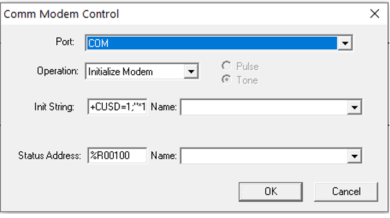
Initialize Modem Option
Modem Control block with ’Initialize Modem’ option is used for execution of modem specific AT commands. Modem specific AT command to be executed is to be entered in ’Init String’ text box provided in control. If AT command execution is successful, then Modem Control block output is enabled else the output is disabled. The status register is updated depending upon the response from modem. The response from modem is stored in consecutive register locations starting from ’status register+1’ address.
Example: Modem control block with ’Initialize Modem’ option is used to get balance left from service provider. The service provider balance request string is entered in ’Init String’ box together with CUSD AT command. As shown below in screen shot. The response from service provider is stored in consecutive register locations starting from ’Status Address + 1’.
NOTE: The command to be sent for balance enquiry is: +CUSD = 1,”*111#”,15 where ”*111#” is string to request left balance in SIM and may vary depending on the service provider.
Return to the Top: GSM Configuration
Modem Status Register Value Definitions
NOTE: At any given time, the modem can service only one of the modes i.e. connectivity with Cscape, data exchange or SMS.
-
SMS transmission and reception (whenever enabled) will be slow when modem is active.
-
Status of ’6’ indicates mode is waiting for connection request from specified client and it is applicable in case of GPRS server mode.
-
When modem returns status ’Connected’, then TX, RX or other communication ladder block can be used to exchange data with destination server according to protocol.
-
Disabling Modem Control ladder block input will disconnect GPRS service. Status register value changes to 65534 (0xFFFE i.e. indicates waiting for modem response for disconnect command) and then to 65535 (0xFFFF).
-
SMS functionality will work based upon Data Transmission Settings SMS Communications window while GSM/GPRS connection is active.
-
Connecting to GPRS network and establishing connection with remote server might take around 3-4minutes.
-
Disconnecting connection with remote server might take 10-20 seconds.
-
If continuous error response is seen in status register or 0xFFFE response is seen while connecting to the modem as default programming port, then check:
-
SIM card is properly inserted in the modem.
-
SIM is enabled for given service (i.e. GPRS or GSM data call).
-
Antenna is connected properly.
-
GPRS configuration parameters in case of GPRS connection.
-
GSM Signal strength at given place.
-
Check VPN connectivity.
-
-
If Default programming port is switched to default serial port option (MJ1) from GSM/GPRS then port might get released after 20-30 sec (i.e. after complete GSM/GPRS connection drop).
Return to the Top: GSM Configuration