Screen Operations for IEC 
See also: IEC 61131 Language Editor Programming
See also: Project Toolbox for IEC
Topic Menu
Home > Project Toolbox > Screen Operations
Switch to Screen 
Also called: CHANGESCREEN or DISPLAYSCREEN
Operator- Changes a screen or displays a screen
Inputs
#NUMBER - (TYPE: DINT![]() Double Integer - [Data Type DINT] - A 32-bit signed value. Double Integers are used where the value of the data is expected to be in the range of -2,147,483,648 to +2,147,483,647.) - #Number format means can able to enter integer value only.
Double Integer - [Data Type DINT] - A 32-bit signed value. Double Integers are used where the value of the data is expected to be in the range of -2,147,483,648 to +2,147,483,647.) - #Number format means can able to enter integer value only.
Outputs
Q - (TYPE: DINT) - Register should be in R type only.
Remarks
Change Screen does not force screen to remain active. Operator may choose to change screen after using various navigation methods (menus, screen jumps, scrolling...). Only one change screen to be active at a time. If a more then one has no affect, however writing directly to %SR1 will change the screen.
ST Language
OUT := ChangeScreen (#Number);
FBD Language
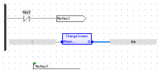
LD Language
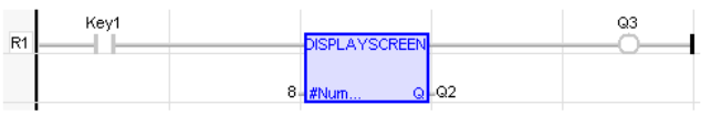
NOTE: Power does not flow through the display coil.
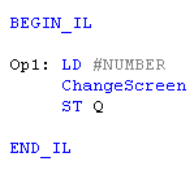
IL Language
Return to the Top: Screen Operations for IEC
Force Screen 
NOTE: This feature requires Enhanced IEC License.
NOTE: Display Screen function block is not supported in Enhanced IEC, when migrating to Enhanced IEC, user must change Display Screen to Force Screen.
Operator - Force a screen.
Input
#Number - (TYPE: DINT) - Screen number that is to be displayed. It can take integer value only.
Output
Q - (TYPE: DINT) - Output Register should be in R type only.
Remarks
Force Screen will override any other user screen being displayed. If more than one display screen is active at a time, the last one in the ladder program is displayed. When a screen is being forced, it can be read from System Register %SR2. NOTE: Display screen is not supported in enhanced IEC, when migrating to enhanced IEC user has to change display screen to Force screen.
ST language
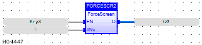
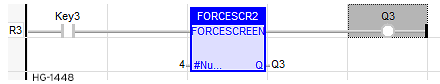
(FORCESCR2 is declared as an instance of FORCESCREEN FB)
Q3:=FORCESCR2 ( Key3, 4 );
FBD Language
LD Language
IL Language
Not Available.
Return to the Top: Screen Operations for IEC
Remote Function Key 
Operator - PressKey block provides a facility to add replicate key to existing Function keys, soft keys and other front panel keys of the OCS.
NOTE: Only Digital input bits can be set as Replicate Keys.
Inputs
#Key: Key Number (TYPE : DINT) - @ReplKey: Key to replicate (TYPE: BOOL)
Outputs
Q : Output (Type: BOOL)
Remarks
The operation of the Replicate Keys (PressKey) is exactly same as the actual keys operations but in OCS run mode only. The Replicate Key works in parallel to actual Keys.
ST Language
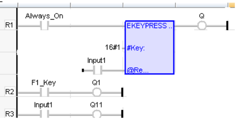
Q:= KEYPRESS (16#1, Input1 (*BOOL*));
Q1:= F1_Key;
Q11:= Input1;
FBD Language

LD Language
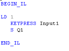
IL Language
Return to the Top: Screen Operations for IEC
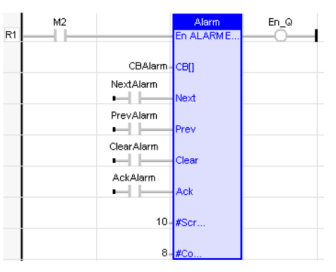
Alarm Handling 
Operator - Creates an alarm handler from a table of contiguous alarm bits in the OCS. Within the table each bit relates to an individual alarm and the status of each alarm is monitored.
Inputs
CB[ ] : Control Block (TYPE : UINT![]() Unsigned Integer - [Data Type UINT] - A 16-bit unsigned value. Unsigned Integers are used where the value of the data is expected to be in the range of -0 (zero) to 65,535.[]) - Each alarm require one 16-bit status register. The registers for multiple alarms are defined in a contiguous block called the Control Block. One bit is written to this register to indicate that the alarm is active. The register also contains sections that indicates the acknowledge and pending status and contains a count for the alarm. By placing the alarm status registers in a section of retentive memory (%R
Unsigned Integer - [Data Type UINT] - A 16-bit unsigned value. Unsigned Integers are used where the value of the data is expected to be in the range of -0 (zero) to 65,535.[]) - Each alarm require one 16-bit status register. The registers for multiple alarms are defined in a contiguous block called the Control Block. One bit is written to this register to indicate that the alarm is active. The register also contains sections that indicates the acknowledge and pending status and contains a count for the alarm. By placing the alarm status registers in a section of retentive memory (%R![]() Retentive 16-bit registers., %M
Retentive 16-bit registers., %M![]() Retentive single-bit registers....) the alarm states will be retained through a power cycle.
Retentive single-bit registers....) the alarm states will be retained through a power cycle.
The following table shows how the bits in the alarm status word (control block) are allocated:
| Bits | 16-12 | 11 | 10 | 9 | 8-1 |
| Definition | Undefined* | Acknowledge | Pending | Active | Alarm Count |
NEXT:(TYPE : BOOL![]() Boolean- [Data Type BOOL] - A single bit, binary value, or register/variable. Boolean points have only two possible values, 'TRUE' or 'FALSE'.) - When this input transitions from low to high, the next (higher alarm number) pending alarm is shown on the display. If the highest alarm is being displayed, the alarm number is not incremented further.
Boolean- [Data Type BOOL] - A single bit, binary value, or register/variable. Boolean points have only two possible values, 'TRUE' or 'FALSE'.) - When this input transitions from low to high, the next (higher alarm number) pending alarm is shown on the display. If the highest alarm is being displayed, the alarm number is not incremented further.
PREV:(TYPE : BOOL) - When this input transitions from low to high, the previous (lower alarm number) pending alarm is shown on the display. If the lowest alarm is being displayed, the alarm number is not decremented further.
CLEAR: (TYPE : BOOL) - When this input transitions from low to high, the currently displayed alarm is cleared if it has already been acknowledged. If it has not been acknowledged this input has no affect. Once the alarm is cleared, the function block immediately searches for the next active alarm screen to display by searching for the next (higher) alarm status register with a Pending bit set. If an alarm is cleared that is still active, the pending bit will be set and if no other alarm is active will continue to be displayed.
ACK: (TYPE : BOOL) - When this input transitions from low to high, the currently displayed alarm is marked as acknowledged. This will set the acknowledge bit in the status register and allow the alarm to be cleared.
#SCREEN1: (TYPE : DINT![]() Double Integer - [Data Type DINT] - A 32-bit signed value. Double Integers are used where the value of the data is expected to be in the range of -2,147,483,648 to +2,147,483,647.) - This defines the first in a block of screens that will be used to display alarm information.
Double Integer - [Data Type DINT] - A 32-bit signed value. Double Integers are used where the value of the data is expected to be in the range of -2,147,483,648 to +2,147,483,647.) - This defines the first in a block of screens that will be used to display alarm information.
#COUNT: (TYPE : DINT) - Count is the total number of alarms defined. This number also sets how many registers are used for status registers, how many text screens are reserved for alarm display.
Remarks
1) The Control Block:
Alarm Count - This is a BYTE![]() Byte - [Data Type BYTE] - A string of 8 consecutive bits. A single BYTE is also the size of a single ASCII character. counter that counts how many times an alarm occurs. The count only increments when the pending bit goes from low to high. To count another alarm event the alarm must be acknowledged, cleared and reactivated. When the count reaches a maximum of 255 it no longer changes until reset. This count can be reset by writing directly to this portion of the register using one of the BYTE instructions.
Byte - [Data Type BYTE] - A string of 8 consecutive bits. A single BYTE is also the size of a single ASCII character. counter that counts how many times an alarm occurs. The count only increments when the pending bit goes from low to high. To count another alarm event the alarm must be acknowledged, cleared and reactivated. When the count reaches a maximum of 255 it no longer changes until reset. This count can be reset by writing directly to this portion of the register using one of the BYTE instructions.
Active - This bit is set by the user's ladder program to indicate an alarm condition has occurred. For example, if the alarm is to indicate an over-temperature condition, have the ladder logic perform a compare, then set this bit if the compare indicates the temperature is greater than a setpoint.
Pending - This bit is set by the function block when the Active bit is high and is reset through the functions block's Clear operation. If the Active bit is high when Pending is reset, a new alarm will be recognized and Pending will be set immediately
Acknowledge - This bit is set by the function block after a pending alarm has been acknowledged.
2) Special Status Bits
Bit 16 of the first status word turns ON when any alarm is pending (but may be acknowledged).
Bit 15 of the first status word turn ON when any alarm is unacknowledged.
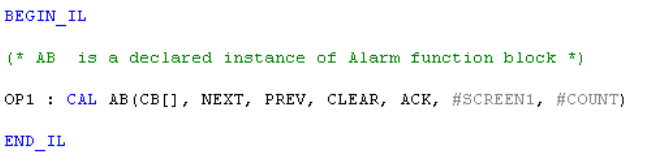
ST Language
(*AB is a declared instance of Alarm function block*)
AB(CB[], NEXT, PREV, CLEAR, ACK, #SCREEN1, #COUNT);
FBD Language
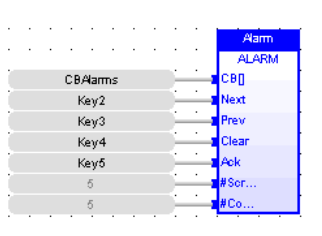
LD Language
IL Language
Return to the Top: Screen Operations for IEC
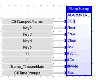
Alarm with Date 
Also called: ALARMSTAMP or Time Stamp
Operator - Creates an alarm handler from a table of contiguous alarm bits in the OCS. Within the table each bit relates to an individual alarm and the status of each alarm is monitored. In addition a time stamp table is maintained for each alarm indicating the last time the alarm was activated, acknowledged and cleared.
Inputs
CB[ ] : Control Block (TYPE : UINT[]) - Each alarm requires one 16-bit status register. The registers for multiple alarms are defined in a contiguous block called the Control Block. One bit is written to this register to indicate that the alarm is active. The register also contains sections that indicates the acknowledge and pending status and contains a count for the alarm. By placing the alarm status registers in a section of retentive memory (%R![]() Retentive 16-bit registers., %M
Retentive 16-bit registers., %M![]() Retentive single-bit registers....) the alarm states will be retained through a power cycle.
Retentive single-bit registers....) the alarm states will be retained through a power cycle.
The following table shows how the bits in the alarm status word (control block) are allocated:
| Bits | 16-12 | 11 | 10 | 9 | 8-1 |
| Definition | Undefined* | Acknowledge | Pending | Active | Alarm Count |
NEXT: (TYPE : BOOL) - When this input transitions from low to high, the next (higher alarm number) pending alarm is shown on the display. If the highest alarm is being displayed, the alarm number is not incremented further.
PREV: (TYPE : BOOL) - When this input transitions from low to high, the previous (lower alarm number) pending alarm is shown on the display. If the lowest alarm is being displayed, the alarm number is not decremented further.
CLEAR: (TYPE : BOOL) - When this input transitions from low to high, the currently displayed alarm is cleared if it has already been acknowledged. If it has not been acknowledged this input has no affect. Once the alarm is cleared, the function block immediately searches for the next active alarm screen to display by searching for the next (higher) alarm status register with a Pending bit set. If an alarm is cleared that is still active, the pending bit will be set and if no other alarm is active will continue to be displayed.
ACK:(TYPE : BOOL) - When this input transitions from low to high, the currently displayed alarm is marked as acknowledged. This will set the acknowledge bit in the status register and allow the alarm to be cleared.
#SCREEN1 : (TYPE : DINT) - This defines the first in a block of screens that will be used to display alarm information.
#COUNT : (TYPE : DINT)- Is the total number of alarms defined. This number also sets how many registers are used for status registers, how many text screens are reserved for alarm display.
#MODE : (TYPE : DINT) - The mode in which the time stamping to be done.
STAMP[ ] : (TYPE : INT[]) - The time & date values are stored in this array of registers.
Remarks
1) The Control Block:
Alarm Count - This is a BYTE counter that counts how many times an alarm occurs. The count only increments when the pending bit goes from low to high. To count another alarm event the alarm must be acknowledged, cleared and reactivated. When the count reaches a maximum of 255 it no longer changes until reset. This count can be reset by writing directly to this portion of the register using one of the BYTE instructions.
Active - This bit is set by the user's ladder program to indicate an alarm condition has occurred. For example, if the alarm is to indicate an over-temperature condition, have the ladder logic performs a compare, then set this bit if the compare indicates the temperature is greater than a set point.
Pending - This bit is set by the function block when the Active bit is high and is reset through the functions block's Clear operation. If the Active bit is high when Pending is reset, a new alarm will be recognized and Pending will be set immediately.
Acknowledge - This bit is set by the function block after a pending alarm has been acknowledged.
Special Status Bits
Bit 16 of the first status word turns ON when any alarm is pending (but may be acknowledged).
Bit 15 of the first status word turn ON when any alarm is unacknowledged.
2) Time Stamp Registers
Time stamping can be set to one of three modes:
-
None - No time stamping is performed and no additional register space is required.
-
Time Only - The time is recorded when each alarm's pending bit becomes active. Each alarm requires three (3) registers starting at the block defined by the time stamping control block. The time is recorded in the same format as the real-time-clock is stored in the system registers.
-
Time and Date - The time and date is recorded when each alarm's pending bit becomes active. Each alarm requires six (6) registers starting at the block defined by the time stamping control block. The time and date is recorded in the same format as the real-time-clock is stored in the system registers.
ST Language
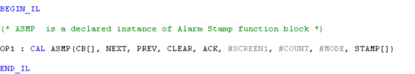
(*ASMP is a declared instance of Alarm Stamp function block*)
ASMP (CB[], NEXT, PREV, CLEAR, ACK, #SCREEN1, #COUNT, #MODE, STAMP[]);
FBD Language
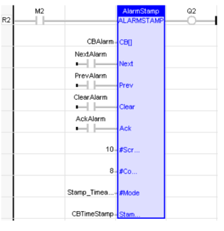
LD Language
IL Language
Return to the Top: Screen Operations for IEC