Serial Port Communication
See also: Hardware Configuration
See also: Serial Communication in Advanced Ladder or Serial Operations for IEC
Note: For wiring, refer to the individual datasheets that can be found on the Document Search Page on the Horner website.
Topic Menu
Some of the Serial Operations in the Project Toolbox allow the program to open a communications port, send and receive data, and close the port. This is useful when interfacing to other devices such as bar code readers, modems, etc.
Comm Port Buffering
The OCS firmware maintains a Transmit Buffer and a Receive Buffer for each available Comm Port. When a Send or Receive element is activated, data is transferred between the appropriate buffer and the ladder program's registers (presumably, %R). The programmer determines which registers are used during configuration of the element.
For a Comm Port Transmit element, the TX Count word contains the number of characters moved from the program registers to the transmit buffer, so long as power is applied to the element. This number can be less than the requested number if the comm port buffer is full. When power is removed from the element, the TX Count Word contains -1 (negative one).
For a Comm Port Receive element, the RX Count Word contains the number of characters moved from the receive buffer in the program area. This number can be less than the requested number if the comm port buffer contains fewer characters than requested.
Return to the Top: Serial Port Communication
Serial Ports and Cscape
The serial port physically present on the OCS unit is primarily intended for use as a Cscape interface port. This is referred to as COMM1 on the OCS . By default, this port uses the CsCAN![]() Horner APG's proprietary network protocol that runs on the Bosch CAN network specifications. Prior to the advent of the OCS. protocol, which is the protocol used by Cscape to communicate to the OCS controllers.
Horner APG's proprietary network protocol that runs on the Bosch CAN network specifications. Prior to the advent of the OCS. protocol, which is the protocol used by Cscape to communicate to the OCS controllers.
If OCS COMM1 is opened using ladder elements, the CsCAN functions are disabled, and the port can not communicate with Cscape through this port. When the port is closed by ladder functions, CsCAN and Cscape communications returns. The port can not be used as a user-defined port and as a CsCAN port simultaneously.
If the port is opened using ladder elements, and the OCS is manually placed into the IDLE mode, the CsCAN functionality and Cscape communications return. When the unit is subsequently placed into the RUN mode, however, it is necessary to reopen the port under ladder program control.
If it is necessary to use the COMM1 port under ladder program control and communicate with Cscape at the same time (i.e., for purposes of debugging) the OCS can be connected to a second OCS unit using CsCAN network and the Pass Through![]() A feature of Horner APG’s OCS products is to connect Cscape “local”, aka directly, to an OCS, then do pass-through programming and monitoring to other “target” OCS controllers connected via CsCAN. Connection features. This method also allows debugging of serial port related features.
A feature of Horner APG’s OCS products is to connect Cscape “local”, aka directly, to an OCS, then do pass-through programming and monitoring to other “target” OCS controllers connected via CsCAN. Connection features. This method also allows debugging of serial port related features.
Return to the Top: Serial Port Communication
Timing and Synchronization
It is possible that the Serial Transmit and Serial Receive elements do not complete within one program scan time. The elements do not pass power until all data bytes have been transferred. This is not usually a problem for transmissions but can be significant for receptions. For example if the ladder program requests 3 bytes of data, but the remote unit only sends two. Or worse, the remote unit has failed and doesn't transmit at all.
It is the programmer's responsibility to write ladder programming code to check the status of the transmit and receive elements and to provide a suitable timeout, if necessary.
Return to the Top: Serial Port Communication
Handshaking
Handshaking is a method whereby the destination end of a transmission can control how much and when data is sent to it.
Note: For purposes of this discussion, source end is defined as the unit which is transmitting data. Destination end is defined as the unit which actually receives the data. Any physical unit may transmit, receive, or both, and may therefore be the source end at one instant and the destination end at the next.
Handshaking is configured with the Comm Port Open element. There are five (5) possible types of handshaking:
-
NONE - There is no handshaking. The source unit sends as many data bytes as it can as fast as possible for a given the baud rate. No consideration is given to the capabilities of the destination end.
-
XON/XOFF - (Also called software handshaking) The destination end keeps track of how many characters it has received and the size of its internal buffers. If the buffer gets full or the unit is otherwise unable to receive further characters, it must transmit the XOFF (transmit off) character. The source end must then stop transmitting data until a subsequent XON character is sent by the destination end. Because there is some heavy software overhead involved, the timing of transmissions is variable. The destination must first determine that it is full and then transmit the XOFF signal. The source end must read the XOFF signal and react to it. In the mean time, several additional data bytes can be sent. It is up to the destination end to ensure that it sends the XOFF signal soon enough that the buffer is not overrun. The XON and XOFF characters are predefined by the ASCII
 ASCII - American Standard Code for Information Interchange - ASCII-coded characters are single-byte values in the range of 0 (zero) to 127. Codes in the range 128 to 255 are not defined by the ASCII standard, but rather by the equipment manufacturer. character set. XON is 11 hex A base-16 numbering system which uses the symbols 0, 1, 2, 3, 4, 5, 6, 7, 8, 9, A, B, C, D, E, F for numeral. or 17 decimal. XOFF is 13 hex or 19 decimal. The XON/XOFF handshaking is most often used where only ASCII values are being sent. XON/XOFF can not be easily used where binary data is involved, because the XON/XOFF codes are also valid binary codes.
 Note: XON/XOFF handshaking usually implies a full duplex
Full-Duplex devices are able to Send and Receive data simultaneously, often referring to RS232 or 4-Wire RS485. (both ends may transmit simultaneously) communications channel as the destination end needs to transmit the XOFF characters at any time (including in the middle of a transmission from the source end). The advantage to XON/XOFF handshaking is that it can be implemented using an easy and cheap three-wire (TX/RX/Common) cable.
-
HARDWARE - [Also called RTS/CTS handshaking.] Hardware handshaking requires extra signals be sent between the two units, thus this is more expensive to implement due to the increased numbers of wires in the interconnecting cables. In operation, the destination end determines that it is empty, and activates its CTS (Clear To Send) signal. In response, the source end sends data so long as the CTS signal remains active. Many devices have the RTS/CTS signals wired directly into the hardware. Thus, an inactive CTS signals from the destination end can instantly shut down the source end. These hardware operations can be very fast because no software control is necessary in this case. Also, this manner of handshaking can be used regardless of the nature of the data being transmitted, ASCII coded or binary.
-
Multi-Drop Full Duplex
Full-Duplex devices are able to Send and Receive data simultaneously, often referring to RS232 or 4-Wire RS485. - In a full-duplex multi-drop situation, all available units are wired in parallel. For receiver circuitry this is no problem so long as the load on the network is not excessive. All units have their receivers enabled at all times. Each message sent through the system is somehow identified by giving it a drop address. All units will receive all messages. All units check the drop address against their own address, and only the unit with the matching address responds. All units maintain their transmitters disabled at all times, except when they need to transmit. When a unit determines that it has something to transmit it turns on its transmitter, sends the necessary data packet, and then disables its transmitter. Full Duplex Full-Duplex devices are able to Send and Receive data simultaneously, often referring to RS232 or 4-Wire RS485. Multi-drop is usually found in multi-master or peer to peer systems, where all units have a more or less equal chance of needing to transmit a message. Often, the units needs to verify that the message they sent are sent correctly so the receiver is left on at all times. The advantage to this system is that many units can be connected to a simple three-wire (RX/RX/Common) cable. The drawback to this system is increased firmware and software complexity.
-
Multi-Drop Half Duplex
Half-duplex devices are able to Send and Receive data, but only one direction at a time, often referring to 2-wire RS485 devices. - Multi-Drop Half-Duplex operation is identical to Full-Duplex except that the transmitting unit's receiver is disabled when the unit is transmitting. All units maintain their transmitters disabled and receivers enabled at all times except when they need to transmit. Usually, protocols dictate that only the unit matching the drop address can transmit. This unit turns on its transmitter, turns off its receiver, sends the necessary data packet, and then disables its transmitter and enables its receiver. Half Duplex Multi-drop is usually found in Master/Slave systems where one unit is designated a Master and all other units are Slaves. The Master transmits a message to one Slave, and then disable it's transmitter. All Slaves hear the message, but only the Slave with the matching "drop address" will turn on its transmitter and respond.
Modem Control
The OCS now has the capabilities to control an external modem. Using the Modem Control element, the OCS can initialize, dial, and hang up the modem. The Auto-Answer mode of the modem, if available, can also be turned ON or OFF.
RS-485 with the OCS
Some OCS units do not provide RS-485![]() An EIA standard that specifies electrical characteristics of drivers and receivers for use in serial communications. Electrical signaling is balanced and multipoint systems are supported. compatible signals. It is necessary to purchase and install a third-party RS-232 to RS-485 converter. In this mode, transmitter control is OCS Signal CTS, available on the DB-9 connector, Pin 8. When the OCS asserts this signal, the converter enables its transmitting section.
An EIA standard that specifies electrical characteristics of drivers and receivers for use in serial communications. Electrical signaling is balanced and multipoint systems are supported. compatible signals. It is necessary to purchase and install a third-party RS-232 to RS-485 converter. In this mode, transmitter control is OCS Signal CTS, available on the DB-9 connector, Pin 8. When the OCS asserts this signal, the converter enables its transmitting section.
Return to the Top: Serial Port Communication
How to Test the Serial Ports
This feature is not available for imx28, XL Prime, Canvas and XL+ series.
Introduction
OCS and RCS products with Engine Firmware Version 8.71 and later have built-in serial port diagnostics. Since multiple serial ports are available in the OCS 3xx/4/5/651, the method implemented to run the tests has changed, starting with Engine Firmware Version 9.53.
Unlike other self-test diagnostics, serial port tests are not executed automatically at power-up. Instead, %SR62 is used to start serial port tests and to obtain test results.
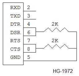
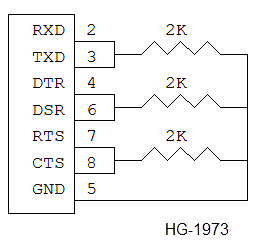
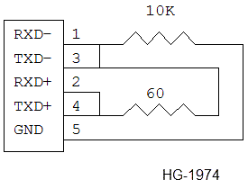
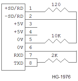
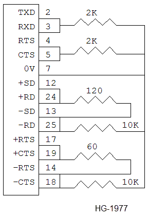
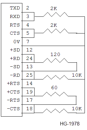
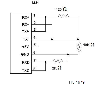
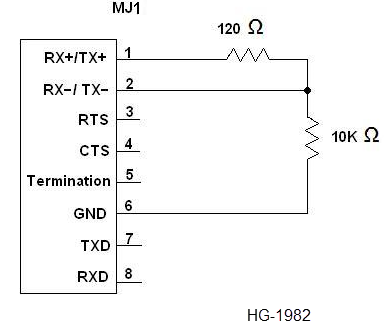
All loopback wiring diagrams are shown with resistors installed. This simulates a loaded communications circuit that simply short-circuiting pins together cannot provide.
OCS /RCS Loopback Wiring (except OCS3xx/4/5/651)
The built-in OCS /RCS serial port tests require the serial port connectors to be wired for loopback, as shown in the following drawings:
|
OCS 400 /RCS RS-232 Handshake Loopback 9-pin Male D-Sub. |
|
OCS /RCS RS-232 Full Loopback 9-pin Male D-Sub |
|
OCS 250 RS-485 Loopback 6-pin Phoenix |
OCS 3xx 260 and OCS 4/5/651 600 AD3/4/5/6 Series Loopback Wiring
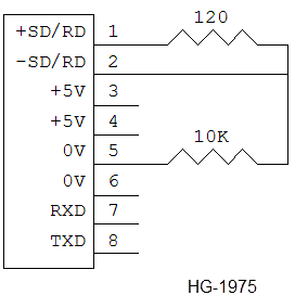
The built-in serial port tests require the serial ports to be wired for loopback as shown in below figures.
Note: For optimal RS485 serial port test results:
-
OCS 3xx 260 DIP switches 6 & 7 should be ON and DIP switch 8 should be OFF.
-
OCS 451/551/651 600 AD4/5/6 series DIP switches 6, 7 and 8 should be ON and DIP switch 5 should be OFF.
|
OCS 3xx/4/5/651 600 AD3/4/5/6 series MJ1/MJ2 RS485 Loopback 8-Pin RJ45 |
|
OCS 3xx/4/5/651 600 AD3/4/5/6 series MJ1/MJ2 Full Loopback 8-Pin RJ45 |
|
OCS 3xx CN1 Full Loopback 25-Pin Male D |
|
OCS 4/5/651 600 series AD4/5/6 CN1 Full Loopback 25-Pin Male D |
|
NX MJ1/XL6 ST PIC400 series 8-Pin RJ45 |

|
MJ2 XLe/XLT BAPIC200 series 8-Pin RJ45 |

|
MJ2 Weidmuller PIC400 series 10-Pin |
|
MJ1 XLE/XLT BAPIC220/PIC240 series 8-Pin RJ45 |
Return to the Top: Serial Port Communication
Running Serial Port Tests
There are seven (7) unique serial port tests, which can be initiated. For each test, %SR62 should be loaded with a specific value to start the test, and then %SR62 should be monitored for test results, according to the following table:
Note: For each test, each of its possible Test Result Errors corresponds to a specific sub-test. The sub-tests are performed in increasing numerical order. If a sub-test fails, testing stops and the corresponding Test Result Error Value is loaded into %SR62. If all tests passed, 0 is loaded into %SR62
| Test |
Test Start (%SR62 Value) |
Possible Test Results (%SR62 Values) |
|---|---|---|
|
OCS / RCS Port 1 RS232 Handshake Only Test |
256 (0100H) |
0 = All Tests Passed 4 = RS232 CTS/RTS Handshake Error 5 = RS232 DSR/DTR Handshake Error |
|
OCS /RCS Port 1 RS232 Full Test |
257 (0101H) |
0 = All Tests Passed 4 = RS232 CTS/RTS Handshake Error 5 = RS232 DSR/DTR Handshake Error 6 = RS232 RXD/TXD Data Error |
|
OCS 250 Port 2 RS485 & RS232 Test |
513 (0201H) |
0 = All Tests Passed 2 = RS485 TXD Disable Error 3 = RS485 RXD/TXD Data Error 4 = RS232 CTS/RTS Handshake Error 5 = RS232 DSR/DTR Handshake Error 6 = RS232 RXD/TXD Data Error |
|
OCS 3xx/4/5/651 600 series AD3/4/5/6 series Port 1 (MJ1) RS485 Only Test |
256 (0100H) |
0 = All Tests Passed 2 = RS485 TXD Disable Error 3 = RS485 RXD/TXD Data Error |
|
OCS 3xx/4/5/651 600 series AD3/4/5/6 series Port 1 (MJ1) RS485 & RS232 Test |
257 (0101H) |
0 = All Tests Passed 2 = RS485 TXD Disable Error 3 = RS485 RXD/TXD Data Error 6 = RS232 RXD/TXD Data Error |
|
OCS 3xx/4/5/651 600 series AD3/4/5/6 series Port 2 (MJ2) RS485 & RS232 Test |
513 (0201H) |
0 = All Tests Passed 2 = RS485 TXD Disable Error 3 = RS485 RXD/TXD Data Error 6 = RS232 RXD/TXD Data Error |
|
OCS 3xx/4/5/651 600 series AD3/4/5/6 series Port 3 (CN1) RS485 & RS232 Test |
769 (0301H) |
0 = All Tests Passed 1 = RS485 CTS/RTS Handshake Error 2 = RS485 TXD Disable Error 3 = RS485 RXD/TXD Data Error 4 = RS232 CTS/RTS Handshake Error 6 = RS232 RXD/TXD Data Error |
| NX/XL6 PIC400 series ST MJ1 RS485 and RS232 Test |
257 (0101H) |
0 = All Tests Passed with CTS/RTS & DSR/DTR on Port 1 shorted. 3 = RS485 RXD/TXD Data Error 4 = RS232 CTS/RTS Handshake Error 5 = RS232 DSR/DTR Handshake Error with CTR/RTS on Port 1 shorted 6 = RS232 RXD/TXD Data Error with CTR/RTS & DSR/DTR on Port 1 shorted |
|
XLe/XLT PIC200 series BA Port 2 (MJ2) RS485 & RS232 Test |
513 (0201H) |
0 = All Tests Passed 3 = RS485 RXD/TXD Data Error 6 = RS232 RXD/TXD Data Error |
| NX PIC400 series CN1 RS485 & RS232 Test |
513 (0201H) |
0 = All Tests Passed 3 = RS485 RXD/TXD Data Error 6 = RS232 RXD/TXD Data Error |
|
XLe/XLT PIC220/240 series BA Port 1 (MJ1) RS232 Only Test |
257 (0101H) |
0 = All Tests Passed 4 = RS232 CTS/RTS Handshake Error 6 = RS232 RXD/TXD Data Error |
Return to the Top: Serial Port Communication