J1939 Protocol Configuration
See also: Hardware Configuration
Topic Menu

|
J1939 Protocol |
J1939 Protocol Overview
The J1939 comes from the international Society of Automotive Engineers (SAE) and works on the physical layer with CAN-high speed according to ISO11898. SAE J1939 defines five layers in the 7-layer OSI network model, and this includes the CAN 2.0b specification. The application focus is on the power trains and chassis of commercial vehicles.
All J1939 packets contain eight bytes of data and a standard header which contains an index called PGN (Parameter Group Number), which is embedded in the message's 29-bit identifier. A PGN is unique numeric identifier that is associated with a specific parameter name. A PGN identifies a message's function and associated data. For example, a PGN defines the parameter value; a device is requesting or the parameter value that a device is sending.
J1939 Protocol Configuration
Select Config button of J1939 protocol in hardware configuration window.

The following window will be displayed.
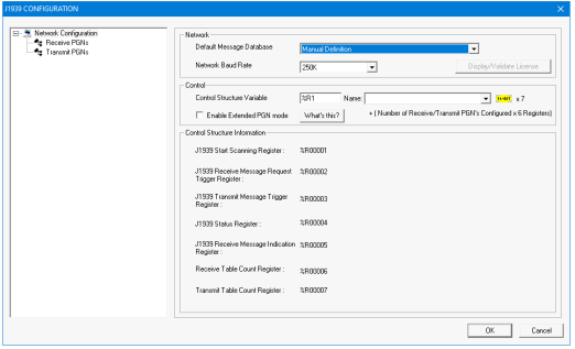
Enable Extended PGN Mode - Selecting this option allows configuration of J1939 extended mode wherein user can configure 32 Transmit and 32 Receive PGNs rather than 15 of each supported in the non extended mode.
Note: When switching from non extended to extended mode, the format of the control block will change to support the additional PGNs flags, so may require modifications to and any control logic accessing the J1939 control block.
Return to the Top: J1939 Protocol Configuration
15 PGN Configuration for J1939
Network
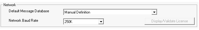
Configure Message Database and Network Baud Rate:
Control
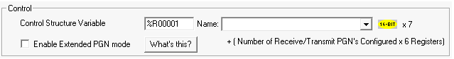
Control Structure Variable - Configure Control structure variable with a length of 7 registers.
Control Structure Information - Once user configures the control structure variable, the variable or register assigned to each option will be displayed in the Control Structure Information.
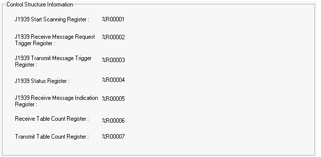
J1939 Start Scanning Register - Used to start / stop J1939 protocol. (%R1 = 1, start J1939 protocol ; %R1 = 0, stop J1939 protocol)
J1939 Receive Message Request Trigger Register - Used to send request message to receive required J1939 message (Bits %R2.1 to R2.15 are used. One bit corresponding one configured message in the table. R2.16 is used to clear “Receive status” register).
J1939 Transmit Message Trigger Register - Used to send trigger based J1939 messages (Bits %R3.1 to R3.15 are used. One bit corresponding one configured message in the table).
J1939 Status Register - Defines the status of J1939 protocol.
%R4.1 – J1939 protocol scanning Stopped
%R4.2 – J1939 protocol Configuration size is incorrect.
%R4.3 – Invalid Rx message Configuration.
%R4.4 – Invalid Tx message Configuration.
%R4.5 – Transmit Message Fail.
%R4.6 – Rx request message Timeout (20sec).
%R4.7 – Received Message data size is less than configured size.
%R4.8 – Invalid Broadcast Announcement Message.
%R4.9 – CAN Overrun Error
%R4.10 – CAN Bus OFF Error
%R4.11 – CAN Bus Passive Error
%R4.12 to %R4.16 – Reserved
J1939 Receive Message Indication Register - J1939 Receive Status Register (Bits %R1004.1 to %R1004.15 are used to indicate reception of configured J1939 messages. Using %R1001.16 bit this register can be cleared)
Receive Table Count Register - Receive Table count (Max 15)
Transmit Table Count Register - Transmit Table count (Max 15)
Receive PGNs
Selecting Receive PGNs displays the following options:
New Receive PGN
Add receive PGNs manually or from J1939 data base drop down.
Once Receive PGNs are added, the same will be displayed in Receive PGNs section.
Selecting the newly added receive PGN displays the following window:

Configure all the fields in Identifier and Data section.
PGN - [PF (PDU
PDU - Protocol Data Unit - A PDU is a specific block of information transferred over a network. Format) & PS (PDU Specific)]
Priority - Range 0-7.
Source Address - Self Node Address.
Destination Address – Address of node in the network from whom you intend to receive the message.
Name - Name of the receive PGN
Bytes - Number Of Bytes to be received (Note: J1939 can receive up to 255 bytes of data)
Mapping - Location to store received data.
Receive Mode
Monitor Mode - An engine control module (ECM) sends some PGN data onto the network at regular intervals. The specific PGNs that are sent vary between ECMs. If the ECM broadcasts a desired PGN’s data on a regular basis, then the mode for that PGN is configured for monitor. The J1939 monitors the network for the PGNs that are configured as monitor mode in the scan table. If it finds a match, then the data is sent. In this mode, the source address is not used.
Request Mode (in ms) - If the desired PGN is not sent on a regular basis, then a request must be made from the J1939 protocol to the device before the data is sent. The mode for these PGNs is configured for request. Requesting requires interaction between the J1939 protocol and a device on the network. The J1939 protocol must send a request message to a device onto the network and receive a reply before that data can be sent. In this mode, the source address is required. If response for requested PGN is not received within the configured timeout period, then firmware will flag the error.
Note: J1939 firmware will indicate received message by setting corresponding bit in Receive Message Status register. It is the responsibility of the user to clear these bits.
Transmit PGNs
Selecting Transmit PGNs displays the following options:
![]()
New Transmit PGN - Add transmit PGNs manually or from J1939 data base drop down. Once transmit PGNs are added, the same will be displayed in transmit PGNs section.
Selecting the newly added transmit PGN displays the following window:

Configure all the fields in Identifier and Data section.
PGN - [PF (PDU
Priority - Range 0-7.
Source Address - Self Node Address.
Name - Name of the receive PGN
Bytes - Number Of Bytes to be transmitted (Note: User can transmit of maximum 8 bytes of data only)
Mapping - Location to store data.
Send
On Trigger Only - In this mode of transmission Cycle time period is configured as 0 (Zero) ms. On transition of Transmit trigger bit from 0 to 1 the XL-J1939 copies transmit data from configured %R![]() Retentive 16-bit registers. registers and sends on to the network. On successful transmission J1939 protocol resets the trigger bit.
Retentive 16-bit registers. registers and sends on to the network. On successful transmission J1939 protocol resets the trigger bit.
On Trigger and on interval (ms) - Required cycle time period is configured with other protocol information. The J1939 protocol copies transmit data from configured %R registers and sends every configured cycle time period.
Note: PGN which is configured for Timed Transmit can also be sent using Trigger Transmit mode, in such case a given PGN will be sent on Trigger and on expiry of configured cycle time value.
Return to the Top: J1939 Protocol Configuration
32 PGN Configuration for J1939
32 PGN configuration structure is divided into three sections:
-
Control Structure Variable - Requires length of 10 registers of data type word.
-
Receive PGN Starting Register - Requires word data type with length = number of PGN configured x 6 registers.
-
Transmit PGN Starting Register - Requires word data type with length = number of PGN configured x 6 registers.
Select Config button of J1939 protocol in hardware configuration window.
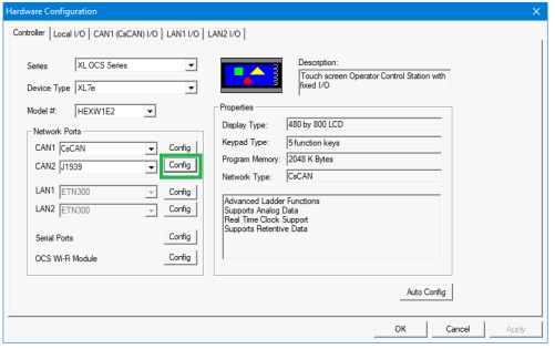
The following window will be displayed.
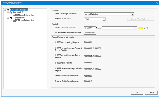
Network
Configure Message Database and Network Baud Rate.
Control
Control Structure Variable - Configure Control structure variable with a length of 10 registers.
Enable Extended PGN Mode - Selecting this option allows configuration of J1939 extended mode wherein user can configure 32 Transmit and 32 Receive PGNs rather than 15 of each supported in the non extended mode.
Note: When switching from non \-extended to extended mode, the format of the control block will change to support the additional PGNs flags, so may require modifications to and any control logic accessing the J1939 control block.
Control Structure Information - Once user configures the control structure variable, the variable or register assigned to each option will be displayed in the Control Structure Information.
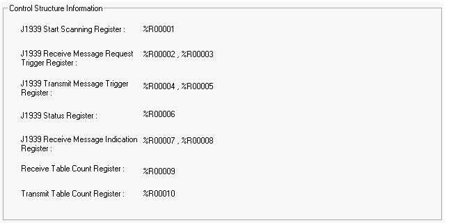
J1939 Start Scanning Register - Used to start/stop J1939 protocol.
J1939 Receive Message Request Trigger Register - J1939 Receive message request trigger bits
J1939 Transmit Message Trigger Register - J1939 Transmit message request trigger bits
J1939 Status Register - Defines the status of J1939 protocol.
Bit 1 – J1939 protocol scanning Stopped
Bit 2 – J1939 protocol Configuration size is incorrect.
Bit 3 – Invalid Rx message Configuration.
Bit 4 – Invalid Tx message Configuration.
Bit 5 – Transmit Message Fail.
Bit 6 – Rx request message Timeout (20sec).
Bit 7 – Received Message data size is less than configured size.
Bit 8 – Invalid Broadcast Announcement Message.
Bit 9 – CAN Overrun Error
Bit 10 – CAN Bus OFF Error
Bit 11 – CAN Bus Passive Error
Bit 12 to 16 – Reserved
J1939 Receive Message Indication Register - J1939 Receive message indication register
Receive Table Count Register - Receive Table count (Max 32)
Transmit Table Count Register - Transmit Table count (Max 32)
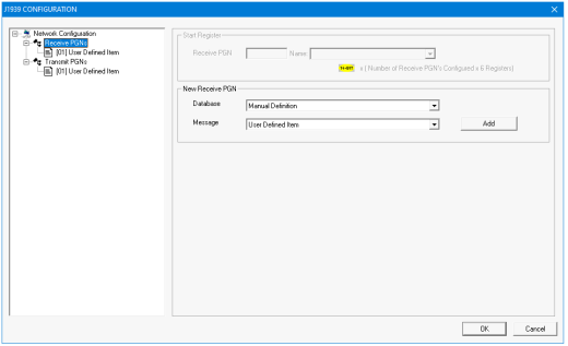
Receive PGNs
Selecting Receive PGNs displays the following options.
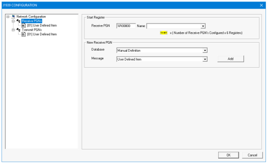
Start Register - Configure receive PGN starting register with a length of size = number of receive PGN required x 6 registers.
New Receive PGN
-
Add receive PGNs manually or from J1939 data base drop down.
-
Once Receive PGNs are added, the same will be displayed in Receive PGNs section.
Selecting the newly added receive PGN displays the following window:
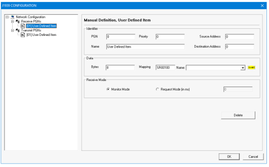
Configure all the fields in Identifier and Data section.
PGN - [PF (PDU
Priority - Range 0-7.
Source Address - Self Node Address.
Destination Address – Address of node in the network from whom you intend to receive the message.
Name - Name of the receive PGN
Bytes - Number Of Bytes to be received (Note: J1939 can receive up to 255 bytes of data)
Mapping - location to store received data.
Receive Mode
Monitor Mode - An engine control module (ECM) sends some PGN data onto the network at regular intervals. The specific PGNs that are sent vary between ECMs. If the ECM broadcasts a desired PGN’s data on a regular basis, then the mode for that PGN is configured for monitor. The J1939 monitors the network for the PGNs that are configured as monitor mode in the scan table. If it finds a match, then the data is sent. In this mode, the source address is not used.
Request Mode (in ms) - If the desired PGN is not sent on a regular basis, then a request must be made from the J1939 protocol to the device before the data is sent. The mode for these PGNs is configured for request. Requesting requires interaction between the J1939 protocol and a device on the network. The J1939 protocol must send a request message to a device onto the network and receive a reply before that data can be sent. In this mode, the source address is required. If response for requested PGN is not received within the configured timeout period, then firmware will flag the error.
Note: J1939 firmware will indicate received message by setting corresponding bit in Receive Message Status register. It is the responsibility of the user to clear these bits.
Transmit PGNs
Selecting Transmit PGNs displays the following options:
![]()
Start Register - Configure transmit PGN starting register with a length of size = number of transmit PGN required x 6 registers.
New Transmit PGN:
-
Add transmit PGNs manually or from J1939 data base drop down.
-
Once transmit PGNs are added, the same will be displayed in transmit PGNs section.
Selecting the newly added transmit PGN displays the following window.
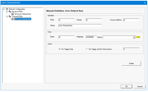
Configure all the fields in Identifier and Data section.
PGN - [PF (PDU
Priority - Range 0-7.
Source Address - Self Node Address.
Name - Name of the receive PGN
Bytes - Number Of Bytes to be transmitted (Note: User can transmit of maximum 8 bytes of data only)
Mapping - location to store data.
Send
On Trigger Only - In this mode of transmission Cycle time period is configured as 0 (Zero) ms. On transition of Transmit trigger bit from 0 to 1 the XL-J1939 copies transmit data from configured %R![]() Retentive 16-bit registers. registers and sends on to the network. On successful transmission J1939 protocol resets the trigger bit.
Retentive 16-bit registers. registers and sends on to the network. On successful transmission J1939 protocol resets the trigger bit.
On Trigger and on interval (ms) - Required cycle time period is configured with other protocol information. The J1939 protocol copies transmit data from configured %R registers and sends every configured cycle time period. NOTE: PGN which is configured for Timed Transmit can also be sent using Trigger Transmit mode, in such case a given PGN will be sent on Trigger and on expiry of configured cycle time value
Receive/Transmit PGN configuration array details
Each PGN data is stored in the array of registers and each PGN requires six registers to store the configuration data. Details given below:
Word 1: Destination Address and Source Address.
Word 2: PGN
Word 3: Priority
Word 4: Number of bytes to be received
Word 5: Scan method or Cycle time
Word 6:
Bit 1 - Auto Forward Enable/Disable
Bit 2 - Trigger and Update Interval Enable/Disable
Bit 3 to 8 - CAN Port
Bit 9 to16 - Not Used
Return to the Top: J1939 Protocol Configuration