High-Speed I/O for the XLE/XLT and X2
See also: Hardware Configuration
See also: General I/O Configuration
Topic Menu

|
High-Speed Counting Capabilities |
Overview XLE/XLT and X2
In addition to the compliment of simple analog and digital I/O, several of the XLE/XLT I/O modules support High Speed Counting (HSC) I/O functions and may also support Pulse Width Modulation (PWM) Output functions. Also, the X2 supports the same functions.
The HSC functions include frequency, totalizing, pulse width, and quadrature![]() Separation in phase by two pulses of 90°. Used on signal channel of feedback devices to detect the direction of motion. measurement. The PWM functions include traditional PWM (with variable rate and duty) and a stepper (limited functionality) with variable acceleration and deceleration rates. To determine function availability, refer to the associated model’s Specification/Installation sheet (Digital DC Input/Output sections).
Separation in phase by two pulses of 90°. Used on signal channel of feedback devices to detect the direction of motion. measurement. The PWM functions include traditional PWM (with variable rate and duty) and a stepper (limited functionality) with variable acceleration and deceleration rates. To determine function availability, refer to the associated model’s Specification/Installation sheet (Digital DC Input/Output sections).
High Speed Counter (HSC) Functions for XLE/T or X2
Three different options are available to reset (or set) the current count:
Configured Counts per Rev Value
When configuring the quadrature function, a value may be specified under the Counts per Rev column. When rotation produces an increasing count, the quadrature accumulator resets to zero on reaching the Counts per Rev count. Alternately, when rotation produces a decreasing count, the quadrature accumulator is set to Counts per Rev – 1 on the count following zero. Specifying zero for this value allows the totalizer to count through the full 32-bit range before resetting. For example, if your encoder outputs 1024 counts per revolution, the value of 1024 can be entered into the configuration for Counts per rev. This will result in a counter that produces counts in the range of 0 to 1023.
Ladder Control
Setting registers %Q17 or Q19 resets quadrature (HSC) 1 or quadrature (HSC) 3 (respectively) with no additional configuration. Setting registers %Q18 or Q20 sets quadrature (HSC) 1 or quadrature (HSC) 3 (respectively) to Counts per Rev – 1.
Direct Digital Input Control (HSC3) [Marker]
When HSC input 1 and 2 are used for quadrature inputs, an additional choice of marker input becomes available for HSC input 3. The marker input is typically part of an encoder or motion system that signals when a cycle of motion is complete. When the marker input is triggered, the accumulator is reset to zero or to Counts per rev - 1 based on rotation direction.
Marker reset operation is enabled when HSC3 is configured for Marker type. Once selected, one of several modes is available for marker operation. These modes can be sub-divided into two groups of marker operation.
-
Asynchronous
 1. Lacking a regular time relationship; not related through repeating time patterns.
2. Not dependent on the scan rate of the OCS.
3. Contrasted with Synchronous modes ignore the quadrature inputs and reset the quadrature accumulator to zero on the configured edge (rising, falling or both). These are the most common settings used. When configuring, asynchronous mode selections are prefixed with the word Async.
1. Lacking a regular time relationship; not related through repeating time patterns.
2. Not dependent on the scan rate of the OCS.
3. Contrasted with Synchronous modes ignore the quadrature inputs and reset the quadrature accumulator to zero on the configured edge (rising, falling or both). These are the most common settings used. When configuring, asynchronous mode selections are prefixed with the word Async. -
Synchronous
In step or in phase, as applied to two or more circuits, devices, or machines. Contrasted with Asynchronous. modes synchronize the reset (or set) to the selected quadrature input and the selected marker polarity. Figure 11.1 below indicates which mode to select based on the markers timing diagram. Consult the documentation provided with your encoder to determine the marker pulse timing.
The Marker input is sampled within 50μs of the associated quadrature edge. It is left to the user to determine if this meets the time constraints of the measured drive.
Note: If the Marker input pulse consecutively spans more than one of the specified edges, quadrature-decoding operation is unpredictable.
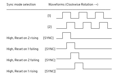
*While not displayed in this figure, modes for low level (inverse logic) are also supported for each state.
The accumulator is reset to zero on the specified edge if rotation is clockwise (as shown in figure above). However, if rotation is reversed, the accumulator is alternately set to Counts per rev – 1 on that same physical edge. When direction is reversed, that same physical edge is seen (by the internal decoder) as having the opposite edge polarity as shown below.
Sync Pulse Mode Table
Definition: CPR most commonly stands for Counts per Revolution, and refers to the number of quadrature decoded states that exist between the two outputs A and B. With both outputs A and B switching between high and low, there exists 2 bits of information represented as 4 distinct states.
|
Mode |
Direction |
A (HSC1) |
B (HSC2) |
Marker (HSC3) |
Reset Value |
|
Async, Reset on rising edge |
|
|
|
Rising |
0 |
|
Async, Reset on falling edge |
|
|
|
Falling |
0 |
|
Async, Reset on both edge |
|
|
|
Both |
0 |
|
High, Reset on 1 rising |
Clockwise |
Rising |
|
High |
0 |
|
“ |
Counter |
Falling |
|
High |
CPR - 1 |
|
Low, Reset on 1 rising |
Clockwise |
Rising |
|
Low |
0 |
|
“ |
Counter |
Falling |
|
Low |
CPR - 1 |
|
High, Reset on 1 falling |
Clockwise |
Rising |
|
High |
CPR - 1 |
|
“ |
Counter |
Falling |
|
High |
0 |
|
Low, Reset on 1 falling |
Clockwise |
Rising |
|
Low |
CPR - 1 |
|
“ |
Counter |
Falling |
|
Low |
0 |
|
High, Reset on 2 rising |
Clockwise |
|
Rising |
High |
0 |
|
“ |
Counter |
|
Falling |
High |
CPR - 1 |
|
Low, Reset on 2 rising |
Clockwise |
|
Rising |
Low |
0 |
|
“ |
Counter |
|
Falling |
Low |
CPR - 1 |
|
High, Reset on 2 falling |
Clockwise |
|
Rising |
High |
CPR - 1 |
|
“ |
Counter |
|
Falling |
High |
0 |
|
Low, Reset on 2 falling |
Clockwise |
|
Rising |
Low |
CPR - 1 |
|
“ |
Counter |
|
Falling |
Low |
0 |
Return to the Top: High-Speed I/O for the XLE/XLT and X2
HSC Register Map for XLE/T and X2
|
Register |
Frequency |
Totalize |
Pulse |
Quad |
|
%AI5-6 |
HSC1 (function) Accumulator |
Quad 1 Acc |
||
|
%AI7-8 |
HSC2 (function) Accumulator |
|
||
|
%AI9-10 |
HSC3 (function) Accumulator |
Quad 2 Acc |
||
|
%AI11-12 |
HSC4 (function) Accumulator |
|
||
|
%AQ1-2 |
|
HSC1 Preset |
|
|
|
%AQ3-4 |
HSC2 Preset |
|||
|
%Q17 |
|
Clear HSC1 |
|
Clear Quad 1 |
|
%Q18 |
Clear HSC2 |
Set Quad 1 |
||
|
%Q19 |
Clear HSC3 |
Clear Quad 2 |
||
|
%Q20 |
Clear HSC4 |
Set Quad 2 |
||
Return to the Top: High-Speed I/O for the XLE/XLT and X2
High Speed Output Functions for XLE/T and X2
When using I/O models equipped with solid-state![]() Generally used to activate lamps, low voltage solenoids, relays, and other low voltage and low current devices. outputs, the first two outputs may be used in conjunction with the first two High-Speed Counter inputs when those inputs are set to ‘Totalize’. When the HSC accumulator matches or exceeds the preset value, these configuration options allow the output to turn ON, turn OFF, toggle, or pulse for a configurable amount of time.
Generally used to activate lamps, low voltage solenoids, relays, and other low voltage and low current devices. outputs, the first two outputs may be used in conjunction with the first two High-Speed Counter inputs when those inputs are set to ‘Totalize’. When the HSC accumulator matches or exceeds the preset value, these configuration options allow the output to turn ON, turn OFF, toggle, or pulse for a configurable amount of time.
Functionality: The HSC Outputs function by comparing an HSC Input accumulator to its configured Preset value. With the Output Pulse option, a Pulse Time value is configured to determine the ON time. The location of these values may be found in the HSC function register map.
Output ON: When the HSC accumulator becomes greater than or equal to the Preset value, the output will turn ON. Otherwise, it is turned OFF.
Output OFF:When the HSC accumulator becomes greater than or equal to the Preset value, the output will turn OFF. Otherwise, it is turned ON.
Output Toggle: When the HSC accumulator becomes equal to the Preset value, the output will toggle, either from OFF to ON, or from ON to OFF.
Output Pulse: When the HSC accumulator becomes equal to the Preset value, the output will turn ON and remain ON until the configured pulse time expires, then turn OFF. If another match occurs during the countdown to turn the output off, the pulse countdown restarts and the output remains ON until the countdown is complete.
Note: The output pulse time resolution is 50μ.
Note: The state of outputs %Q1 and %Q2 are not reflected in their respective registers when selected for operation other than ‘Normal’.
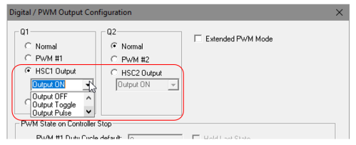
Example 1:
Turn HSC1 Output ON if HSC accumulator 1 exceeds a count of 100,000.
Assuming HSC #1 is already configured to ‘Totalize’:
-
Select ‘HSC1 Output’ and the ‘Output ON’ option
-
Load UDINT
Unsigned Double Integer - [Data Type UDINT] - A 32-bit unsigned value. Unsigned Double Integers are used where the value of the data is expected to be in the range of 0 (zero) to 4,294,967,296. value of 100,000 into %AQ1-2 HSC1 Preset value -
Download the program and input pulses to HSC #1
-
Observe UDINT %AI5-6 HSC1 Accumulator value for the accumulated count.
-
When %AI5-6 HSC1 Accumulator reaches and exceeds the Preset value, the output Q1 will turn ON.
-
The output Q1 will remain on until HSC1 is cleared with the %Q17 bit.
Example 2:
Pulse the Q2 Output for 100 milliseconds when HSC accumulator 2 matches the value of 50,000.
-
Assuming HSC #2 is already configured to ‘Totalize’:
-
Select ‘HSC2 Output’ and the ‘Output Pulse’ option
-
Load UDINT value of 50,000 into %AQ3-4 HSC2 Preset value
-
Load UDINT value of 100,000 into %AQ27-28 Pulse Time
-
Download the program and input pulses to HSC #2
-
When %AI7-8 HSC2 Accumulator becomes equal to 50,000, the output Q2 will turn ON for 100 milliseconds and then turn OFF.
Return to the Top: High-Speed I/O for the XLE/XLT and X2
Pulse Width Modulation (PWM) Functions for XLE/T and X2
On units that support the PWM, two dedicated outputs are available that can be configured for one of four modes of operation. Those modes are Normal, PWM, HSC (count = PV) and Stepper.
PWM Pulse Width Modulation (PWM) - A technique for generating a DC voltage level from a higher constant DC voltage. The constant input voltage is chopped to produce pulses at a constant period and constant amplitude. Modulating the pulse width (duration) controls the average voltage of the output. Registers for XLE/T and X2
| AQ1 – PWM1 Duty Cycle |
| AQ2 – Reserved |
| AQ3 – PWM2 Duty Cycle |
| AQ4 – Reserved |
| AQ5 – PWM1 Pre-Scale |
| AQ6 – PWM2 Pre-Scale |
| AQ7 – PWM1 Period |
| AQ8 – PWM2 Period |
PWM Functions Register Map for XLE/T and X2
|
Register |
PWM |
HSC |
Stepper |
|
%AQ1 |
PWM1 Duty Cycle (32-bit) |
HSC1 Preset Value |
Start Frequency |
|
%AQ2 |
Run Frequency |
||
|
%AQ3 |
PWM2 Duty Cycle (32-bit) |
HSC2 Preset Value |
Accel Count (32-bit) |
|
%AQ4 |
|||
|
%AQ5 |
PWM Prescale (32-bit) |
|
Run Count (32-bit) |
|
%AQ6 |
|||
|
%AQ7 |
PWM Period (32-bit) |
|
Decel Count (32-bit) |
|
%AQ8 |
|||
|
%Q1 |
|
|
Run |
|
%I30 |
|
|
Ready/Done |
|
%I31 |
Error |
When either Q1 or Q2 is configured for HSC operation, HSC1 or HSC2 totalize functions are extended to allow respective direct output control based on a comparison of the current count and a preset value (PV). See totalize in the HSC section above for more information.
Stepper Function for XLE/T and X2
When Q1 is configured for Stepper, the stepper function is enabled at the Q1 output. Only one stepper function and output is available.
Note: When Q1 is configured for stepper operation, Q2 operation is limited to direct digital output.
The Stepper requires five parameters (%AQ![]() 16-bit output registers used to send analog information such a voltages, levels, or speed settings to an attached device.s) to be set for operation. These parameters may be set at run-time but are ‘latched’ when the stepper is commanded to start.
16-bit output registers used to send analog information such a voltages, levels, or speed settings to an attached device.s) to be set for operation. These parameters may be set at run-time but are ‘latched’ when the stepper is commanded to start.
-
Start Frequency (cycles per second) - This value (%AQ1) sets the frequency for the first cycle during the acceleration phase and the frequency of the last cycle during the deceleration phase. When an acceleration or deceleration count is specified, the Start Frequency must be greater than zero (0) and must not exceed the run frequency or an error is generated.
-
Run Frequency (cycles per second) - This value (%AQ2) sets the frequency for the last cycle during the acceleration phase, the consistent frequency during the run phase, and the frequency of the first cycle during the deceleration mode. The Run Frequency must be greater than zero (0) and must not exceed 5000 cycles/sec. or an error is generated.
-
Acceleration Count - This value (%AQ3-4) sets the number of cycles to occur within the acceleration phase. The frequency of the cycles within this mode will vary linearly between the specified Start and Run frequency. The Accel count must not equal 1 or an error is generated. Setting this value to zero (0) disables this phase.
-
Run Count - This value (%AQ5-6) sets the number of cycles to occur within the run phase. The frequency of the cycles within this mode is constant at the specified Run frequency. The Run count may be any value. Setting this value to zero disables this phase.
-
Deceleration Count - This value (%AQ7-8) sets the number of cycles to occur within the deceleration phase. The frequency of the cycles within this phase will vary linearly between the specified Run and Stop frequency. The Decel count must not equal 1 or an error is generated. Setting this value to zero disables this phase.
Boolean Boolean- [Data Type BOOL] - A single bit, binary value, or register/variable. Boolean points have only two possible values, 'TRUE' or 'FALSE'. registers to Provide Stepper Status
-
Ready/Done - A high indication on this register (%I30) indicates the stepper sequence can be started (i.e. not currently busy).
-
Error - A high indication on this register (%I31) indicates that one of the analog parameters specified above is invalid or the stepper action was aborted before the operation was complete. This register is cleared on the next start command if the error was corrected.
The stepper requires one discrete register (%Q1) to control the stepper action. Setting this register starts the stepper cycle. This register must remain set to complete the entire cycle. Clearing this register before the cycle is complete aborts the step sequence and sets the error bit.
Note: Setting the PLC mode to Stop while the stepper is in operation causes the stepper output to immediately drop to zero and the current stepper count to be lost.
Note: Stepper output level may cause damage or be incompatible with some motor driver inputs. Consult drive documentation to determine if output level and type is compatible.
Return to the Top: High-Speed I/O for the XLE/XLT and X2
PWM Examples for XLE/T and X2
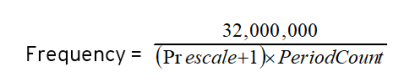
All of the PWM examples use the following formula.
Example 1
To get a 50% Duty Cycle @ 10 kHz waveform on PWM1:
Set %AQ1 = 50 (duty cycle count)
Set %AQ5 = 30 (prescale count)
Set %AQ7 = 100 (period count)
Example 2
To get a 50% Duty Cycle on PW1 and 90 % Duty Cycle on PWM2 @ 1 kHz waveform:
Set %AQ1 = 500 (duty cycle count)
Set %AQ3 = 900 (duty cycle count)
Set %AQ5-6 = 30 (prescale count)
Set %AQ7-8 = 1000 (period count)
Example 3
To turn PWM 1 output ON all the time
Set %AQ1-2 = Same value as AQ7-8 (duty cycle count)
Set %AQ5-6 = Any value (prescale count)
Set %AQ7-8 = Non-Zero value (period count)
Example 4
To turn PWM 1 output OFF all the time
Set %AQ1-2 = 0 (duty cycle count)
Set %AQ5-6 = Any value (prescale count)
Set %AQ7-8 = Any value <or> 0 (period count)
STP Examples for XLE/T and X2
Example 1
10,000,000 steps control sequence
The following example starts at 2.5kHz and ramps up to 5kHz during the first 1,000,000 steps. Then, it runs at 5kHz for the next 8,000,000 steps. Finally, during the last 1,000,000 steps it slows to a stop.
Set %AQ1 = 2500 (Hz) {Start Frequency}
Set %AQ2 = 5000 (Hz) {Run Frequency}
Set %AQ3-4 = 1000000 (Steps) {Accel Count}
Set %AQ5-6 = 8000000 (Steps) {Run Count}
Set %AQ7-8 = 1000000 (Steps) {Decel Count}
Example 2
5,000,000 steps control sequence
The following example starts at 0.5kHz and ramps up to 1kHz during the first 2,000,000 steps. Then, it runs at 1kHz for the next 2,000,000 steps. Finally, during the last 1,000,000 steps it slows to a stop.
Set %AQ1 = 500 (Hz) {Start Frequency}
Set %AQ2 = 1000 (Hz) {Run Frequency}
Set %AQ3-4 = 2000000 (Steps) {Accel Count}
Set %AQ5-6 = 2000000 (Steps) {Run Count}
Set %AQ7-8 = 1000000 (Steps) {Decel Count}
Example 3
6,000,000 steps control sequence
The following example starts at 50Hz and ramps up to 250Hz during the first 150,000 steps. Then, it runs at 250Hz for the next 5,500,000 steps. Finally, during the last 350,000 steps it slows to a stop.
Set %AQ1 = 50 (Hz) {Start Frequency}
Set %AQ2 = 250 (Hz) {Run Frequency}
Set %AQ3-4 = 150000 (Steps) {Accel Count}
Set %AQ5-6 = 5500000 (Steps) {Run Count}
Set %AQ7-8 = 350000 (Steps) {Decel Count}
Note: The highest usable frequency is 65kHz for the PWM output. This is only achievable on a Model 6 unit, Models 2-5 max output frequency is approximately 10kHz.
Return to the Top: High-Speed I/O for the XLE/XLT and X2