High Speed I/O General Overview and Defaults
See also: General I/O Configuration
See also: High-Speed I/O for the XLE/XLT and X2
See also CNX116 Dynamic I/O Configuration
See also: AD 100 Dynamic I/O Configuration
See also: DAC107 Dynamic I/O Configuration
See also: HSC840 Dynamic I/O Configuration
Topic Menu
High-Speed I/O Overview

|
High-Speed Counting Capabilities |
In addition to the compliment of simple analog and digital I/O, some OCS I/O modules support High Speed Counting (HSC) I/O functions and may also support Pulse Width Modulation (PWM![]() Pulse Width Modulation (PWM) - A technique for generating a DC voltage level from a higher constant DC voltage. The constant input voltage is chopped to produce pulses at a constant period and constant amplitude. Modulating the pulse width (duration) controls the average voltage of the output.) Output functions (non-relay modules). The HSC functions include Internal Timing, Frequency, Totalizer
Pulse Width Modulation (PWM) - A technique for generating a DC voltage level from a higher constant DC voltage. The constant input voltage is chopped to produce pulses at a constant period and constant amplitude. Modulating the pulse width (duration) controls the average voltage of the output.) Output functions (non-relay modules). The HSC functions include Internal Timing, Frequency, Totalizer![]() A counter that sums the total number of cycles applied to its input., Pulse Width Measurement (PWM), Period Measurement, and Quadrature. The PWM functions include traditional PWM (with variable rate and duty cycle) and a Stepper Function (limited functionality) with variable acceleration and deceleration rates. To determine function availability, refer to the associated model’s datasheet (Digital DC Input/Output sections) on the Horner Website's Documentation Page page.
A counter that sums the total number of cycles applied to its input., Pulse Width Measurement (PWM), Period Measurement, and Quadrature. The PWM functions include traditional PWM (with variable rate and duty cycle) and a Stepper Function (limited functionality) with variable acceleration and deceleration rates. To determine function availability, refer to the associated model’s datasheet (Digital DC Input/Output sections) on the Horner Website's Documentation Page page.
The OCS contains a Field-Programmable Gate Array (FPGA![]() Field-programmable Gate Array) , which is an integrated configurable circuit that allows the controller to be programmed to have either two high-speed counters or four high-speed counters. The OCS ships with two high-speed counters, but a customer can contact Horner Technical Support [Refer to Help for Cscape ] to receive a file that will configure the unit to have four. These modes are not supported simultaneously. Two counter mode supports Quadrature
Field-programmable Gate Array) , which is an integrated configurable circuit that allows the controller to be programmed to have either two high-speed counters or four high-speed counters. The OCS ships with two high-speed counters, but a customer can contact Horner Technical Support [Refer to Help for Cscape ] to receive a file that will configure the unit to have four. These modes are not supported simultaneously. Two counter mode supports Quadrature![]() Separation in phase by two pulses of 90°. Used on signal channel of feedback devices to detect the direction of motion. mode and two stepper outputs, while four counter mode does not support Quadrature mode and supports only one stepper output.
Separation in phase by two pulses of 90°. Used on signal channel of feedback devices to detect the direction of motion. mode and two stepper outputs, while four counter mode does not support Quadrature mode and supports only one stepper output.
HSC Glossary
|
Glossary of High Speed I/O Terms |
|
|---|---|
|
Register used to accumulate or store up a sum or count of many items or events. |
|
|
Clear |
A special function to zero out the value in a specific register. (Not used with Frequency or Period Measurement.) |
|
Disable |
A special function to prevent the counter from running. |
|
A sensor or transducer for converting rotary motion or position to a series of electronic pulses |
|
|
An integrated, configurable circuit that allows the controller to be programmed to have either two high-speed counters or four quadrature counters. |
|
|
The number of times an electromagnetic signal repeats an identical cycle in a unit of time, usually one second. |
|
|
A special function that uses a digital logic circuit to store one or more bits. A latch has a data input, a clock input and an output. When the clock input is active, data on the input is "latched" or stored and transferred to the output register either immediately or when the clock input goes inactive. The output retains its value until the clock goes active again. |
|
|
Input into the OCS that indicates a particular position. Typically, an encoder has a marker output that represents a specific point in the rotation. |
|
|
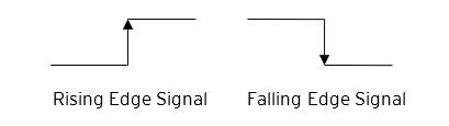
A Polarity pull-down box is associated with each function and indicates the manner in which the trigger happens (e.g., High Level, Low Level, Falling Edge, Rising Edge). |
|
|
A special function used to trigger loading of a value into a register upon an event. (Not used with Frequency or Period Measurement.) |
|
|
A high-speed device that expresses the phase relationship between two periodic quantities of the same period when the phase difference between them is one fourth of a period. A coupler in which the two output signals are 90° out of phase. |
|
|
A counter that sums the total number of cycles applied to its input. |
|
Return to the Top: High Speed I/O General Overview and Defaults
High-Speed Counters Functions
Most controllers support two high-speed, configurable counters. There are four dedicated inputs that can be configured to a number of different options. Each of the two counters can run in one of five modes. Those modes are Totalizer Frequency, Pulse Width Measurement, Period Measurement, and Quadrature Measurement. For some modes, more than one HSC input may be consumed. The measurement values are provided to ladder in a %AI![]() 16-bit input registers used to gather analog input data such as voltages, temperatures, and speed settings coming from an attached device. register (see mapping below).
16-bit input registers used to gather analog input data such as voltages, temperatures, and speed settings coming from an attached device. register (see mapping below).
Frequency
In frequency mode, the frequency of the input signal is written to the accumulator![]() A register/variable used to gather or accumulate a total of time, counts, items, or events. in terms of Hertz (cycles/second). When using frequency mode, four update selections are provided which specify the width of the sample window.
A register/variable used to gather or accumulate a total of time, counts, items, or events. in terms of Hertz (cycles/second). When using frequency mode, four update selections are provided which specify the width of the sample window.
Note: Selecting a shorter sample window provides a quicker measurement (faster response) but lowers the frequency accuracy (resolution) and increases the minimum frequency measurement limit. In this mode the Disable![]() When the disable function is active it will “disable” the high-speed inputs and no longer count pulses until it is re-enabled. and Latch
When the disable function is active it will “disable” the high-speed inputs and no longer count pulses until it is re-enabled. and Latch![]() When the Latch function is active it takes the current value of the Accumulator and moves it into the “Latch Value” register special functions are allowed.
When the Latch function is active it takes the current value of the Accumulator and moves it into the “Latch Value” register special functions are allowed.
Totalize
In Totalize![]() A counter that sums the total number of cycles applied to its input. Mode, the accumulator
A counter that sums the total number of cycles applied to its input. Mode, the accumulator![]() A register/variable used to gather or accumulate a total of time, counts, items, or events. is simply incremented or decremented each time the input transitions in a specific direction.
A register/variable used to gather or accumulate a total of time, counts, items, or events. is simply incremented or decremented each time the input transitions in a specific direction.
The Totalizer supports the following modes:
|
Internal |
This mode ties the input to the counter to an internal 10MHz or 1MHz clock. The special functions can be used to accurately time events. |
|
This increments the accumulator NOTE: Two inputs can be assigned. Either input can cause the counter to increment. The second input can also be disabled. |
|
|
This decrements the accumulator when the input is enabled. NOTE: Two inputs can be assigned. Either input can cause the counter to decrement. The second input can also be disabled. |
|
|
Up/Down (Input 1 Up/Input 2 Down) |
In this mode, input 1 (assigned to any of the four inputs) increments the counter, while input 2 (also assigned to any of the 4 inputs) decrements the counter. |
|
Clk/Dir (Input 1 Clk, Input 2 Dir) |
This mode uses input 1 as a clock signal to increment or decrement the counter and then uses input 2 to decide the direction. Input 2 disabled increments the counter, while input 2 enabled decrements the counter. |
Note: The Totalize mode enables the Disable, Latch Preload, and Clear special functions.
Note: Counter triggers off the rising edge of the signal.
Resetting the Current Count
Three different options are available to reset the current count. They are:
-
When configuring the Totalize function, a value may be specified under the Counts per Rev column. When the totalizer accumulator
 A register/variable used to gather or accumulate a total of time, counts, items, or events. reaches this value - 1, the accumulator will reset to zero on the next count. Specifying zero for this value allows the totalizer to count through the full 32-bit range before resetting.
-
Setting registers %Q17-20 reset HSC1-4 (respectively) with no additional configuration. When these registers are asserted, the associated totalizer accumulator is reset and held at zero (level sensitive).
-
Input Control (HSC1 and HSC2 only) - HSC3 (%I
Single-bit input registers. Typically, an external switch is connected to the registers.11) and HSC4 (%I12) may be configured as hardware digital reset signals for HSC1 and HSC2 (respectively). To enable these inputs as reset signals, specify the type as Totalize Reset. Note: The corresponding Totalize HSC must be previously configured before this option is available. The direct digital reset controls are edge sensitive with the edge polarity The orientation of voltage or current. For example, the polarity of the power connection on an OCS is the positive voltage source (24VDC) goes to the “+” input and ground (0VDC) goes to the “–“ input. If these were flipped, it would be Reverse Polarity. configurable.
Maximum direct digital reset latency is 100μs.
The totalize function also supports an option which compares the current accumulator value with a supplied Preset Value (PV), which is provided through a %AQ![]() 16-bit output registers used to send analog information such a voltages, levels, or speed settings to an attached device., and drives a physical digital output based on the that comparison.
16-bit output registers used to send analog information such a voltages, levels, or speed settings to an attached device., and drives a physical digital output based on the that comparison.
Note: This option (available for HSC1 and HSC2 only) drives Q1 or Q2 output point (respectively) once the associated totalizer accumulator![]() A register/variable used to gather or accumulate a total of time, counts, items, or events. reaches (or exceeds) the PV value. To enable this function, the corresponding PWM
A register/variable used to gather or accumulate a total of time, counts, items, or events. reaches (or exceeds) the PV value. To enable this function, the corresponding PWM![]() Pulse Width Modulation (PWM) - A technique for generating a DC voltage level from a higher constant DC voltage. The constant input voltage is chopped to produce pulses at a constant period and constant amplitude. Modulating the pulse width (duration) controls the average voltage of the output. function output (Q1 or Q2) must be configured for HSCx Output.
Pulse Width Modulation (PWM) - A technique for generating a DC voltage level from a higher constant DC voltage. The constant input voltage is chopped to produce pulses at a constant period and constant amplitude. Modulating the pulse width (duration) controls the average voltage of the output. function output (Q1 or Q2) must be configured for HSCx Output.
Note: Q1 and Q2 are PWM function outputs that may be configured independently as one of the following: standard digital output, PWM, HSCx or stepper output.
Preset values may be modified during run-time. A preset value of zero disables (resets) the totalizer compares function output causing the output to remain low.
Pulse Width Measurement or PWM
In Pulse Width Measurement mode, the high-speed input can measure the width of a pulse stream in one of two modes and provides a continuous indication of the last sampled value. In this mode the Disable![]() When the disable function is active it will “disable” the high-speed inputs and no longer count pulses until it is re-enabled. and Latch
When the disable function is active it will “disable” the high-speed inputs and no longer count pulses until it is re-enabled. and Latch![]() When the Latch function is active it takes the current value of the Accumulator and moves it into the “Latch Value” register special functions are allowed.
When the Latch function is active it takes the current value of the Accumulator and moves it into the “Latch Value” register special functions are allowed.
-
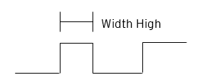
Width High 1μs Counts – In this sub-mode the accumulator
A register/variable used to gather or accumulate a total of time, counts, items, or events. value will contain the number of 1μs counts the pulse is high.
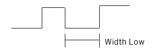
-
Width Low 1μs Counts - In this sub-mode the accumulator value will contain the number of 1μs counts the pulse is low.
Period Measurement
In period measurement mode, the high-speed input can measure the period of a pulse stream in one of two modes and provides a continuous indication of the last sampled value. In this mode the Disable and Latch special functions are allowed.
-
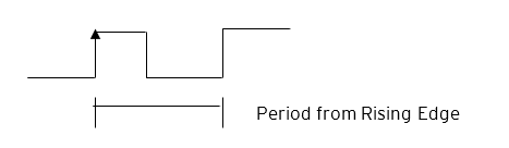
Period Rising Edges 1μs Counts – In this sub-mode the period of the input signal is reported in one (1) μs units. The period measurement will start on the rising edge of the input.
-
Period Falling Edges 1μs Counts – In this sub-mode the period of the input signal is reported in one (1) μs units. The period measurement will start on the falling edge of the input.

Quadrature
Quadrature![]() Separation in phase by two pulses of 90°. Used on signal channel of feedback devices to detect the direction of motion. mode uses two HSC inputs, any of the eight HSC inputs can be assigned for this purpose. Quadrature mode works much like the Totalize function except the accumulator
Separation in phase by two pulses of 90°. Used on signal channel of feedback devices to detect the direction of motion. mode uses two HSC inputs, any of the eight HSC inputs can be assigned for this purpose. Quadrature mode works much like the Totalize function except the accumulator![]() A register/variable used to gather or accumulate a total of time, counts, items, or events. will automatically increment or decrement based on the rotation phase of the two inputs. See the following example for more details. Quadrature inputs are typically used for reporting the value (position)of an encoder.
A register/variable used to gather or accumulate a total of time, counts, items, or events. will automatically increment or decrement based on the rotation phase of the two inputs. See the following example for more details. Quadrature inputs are typically used for reporting the value (position)of an encoder.
Two modes are available for quadrature that select whether the accumulator counts up or down when the phase of input 1 leads input 2. Check the encoder’s documentation to determine the output form it uses or try both modes to determine if the encoder counts up when expected.
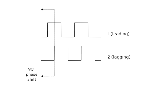
Using the above waveforms and a HSC input configuration of “Quadrature” - “1 leads 2, count up,” the accumulator will count up when 1 is rising and 2 is low, 1 is high and 2 is rising, 1 is falling and 2 is high, and when 1 is low and 2 is falling. This results in 4 counts per revolution. In order to determine the number of cycles, the accumulator would have to be divided by 4.
Marker reset operation is configured in the special operations and can be assigned to any of the 4 high speed inputs or can be assigned to be controlled by a “Q” bit in ladder.
Note: The quadrature mode enables the Disable![]() When the disable function is active it will “disable” the high-speed inputs and no longer count pulses until it is re-enabled., Latch
When the disable function is active it will “disable” the high-speed inputs and no longer count pulses until it is re-enabled., Latch![]() When the Latch function is active it takes the current value of the Accumulator and moves it into the “Latch Value” register, Preload
When the Latch function is active it takes the current value of the Accumulator and moves it into the “Latch Value” register, Preload![]() When the pre-load function is active it will take the value from the “Preload” register and put it into the “Accumulator” for the corresponding Counter., Clear
When the pre-load function is active it will take the value from the “Preload” register and put it into the “Accumulator” for the corresponding Counter., Clear![]() When the clear function is active it will move a value of 0 into the “Accumulator” for the corresponding counter., and Marker
When the clear function is active it will move a value of 0 into the “Accumulator” for the corresponding counter., and Marker![]() When the marker function is enabled, it acts as a dynamic enable/disable for the Disable, Latch, Preload and Clear functions. So, if the marker is enabled and “Assigned %Q” is selected then both the “Disable” and the “Disable Marker” bits need to be set high in order to disable the high-speed input. If the Marker is set for one of the inputs then the input will need to be “High” in order to use any of the Disable, clear, preload, or Latch functions. special functions.
When the marker function is enabled, it acts as a dynamic enable/disable for the Disable, Latch, Preload and Clear functions. So, if the marker is enabled and “Assigned %Q” is selected then both the “Disable” and the “Disable Marker” bits need to be set high in order to disable the high-speed input. If the Marker is set for one of the inputs then the input will need to be “High” in order to use any of the Disable, clear, preload, or Latch functions. special functions.
Register Match
Totalizer![]() A counter that sums the total number of cycles applied to its input. and Quadrature
A counter that sums the total number of cycles applied to its input. and Quadrature![]() Separation in phase by two pulses of 90°. Used on signal channel of feedback devices to detect the direction of motion. counter modes support a Register Match function. When the accumulator
Separation in phase by two pulses of 90°. Used on signal channel of feedback devices to detect the direction of motion. counter modes support a Register Match function. When the accumulator![]() A register/variable used to gather or accumulate a total of time, counts, items, or events. value matches either the Match 1 or Match 2 value configured in the corresponding %AQ
A register/variable used to gather or accumulate a total of time, counts, items, or events. value matches either the Match 1 or Match 2 value configured in the corresponding %AQ![]() 16-bit output registers used to send analog information such a voltages, levels, or speed settings to an attached device. registers, a high-speed output can Turn On, Turn Off, or Toggle. An internal %I
16-bit output registers used to send analog information such a voltages, levels, or speed settings to an attached device. registers, a high-speed output can Turn On, Turn Off, or Toggle. An internal %I![]() Single-bit input registers. Typically, an external switch is connected to the registers. register mirrors the output state whether the high-speed output is configured or not. The output can be reset in program logic using the corresponding %Q
Single-bit input registers. Typically, an external switch is connected to the registers. register mirrors the output state whether the high-speed output is configured or not. The output can be reset in program logic using the corresponding %Q![]() Single-bit output registers. Typically, these bits are connected to an actuator, indicator light or other physical outputs. registers.
Single-bit output registers. Typically, these bits are connected to an actuator, indicator light or other physical outputs. registers.
-
2-Counter Mode has Register Match support for both counters.
-
4-Counter Mode has Register Match support only for counters 1 and 2.
-
The High-Speed Outputs are %Q1 for Counter 1 and %Q2 for Counter 2. They operate as high-speed outputs, independent of the controller scan rate, when configured as ‘HSC Output’ in the Digital Out/PWM
Pulse Width Modulation (PWM) - A technique for generating a DC voltage level from a higher constant DC voltage. The constant input voltage is chopped to produce pulses at a constant period and constant amplitude. Modulating the pulse width (duration) controls the average voltage of the output. configuration in Cscape. -
The High-Speed Output state reflects in the status register “High Speed Out”, e.g. %I1603 for Counter 1 (the update speed of the status bit is scan rate dependent)
-
The High-Speed Output can be reset through ladder with the assigned output, e.g. %Q1606 for Counter 1
-
Both Match 1 and Match 2 values will trigger the match function.
-
If the output is already triggered by any Match register while using ‘Turn On’ or ‘Turn Off’ modes, subsequent matches will not affect the output.
-
If using ‘Toggle’ mode, every match of either Match value will toggle the output to the opposite state.
HSC Functions
The high-speed input on an OCS contains many optional tasks, all of which can be disabled, or set to an internal pre-assigned register (Assigned %Q) or to one of the external High-speed inputs (External Input #1, 2, 3 or 4).
Also, they can be set as an “overflow interrupt” or “underflow interrupt” meaning that they will occur when either the Overflow, or Underflow input has been activated.
-
Disable
When the disable function is active it will “disable” the high-speed inputs and no longer count pulses until it is re-enabled.: When the disable function is active it will “disable” the high-speed inputs and no longer count pulses until it is re-enabled -
Latch
When the Latch function is active it takes the current value of the Accumulator and moves it into the “Latch Value” register: When the Latch function is active it takes the current value of the Accumulator and moves it into the “Latch Value” register -
Preload
When the pre-load function is active it will take the value from the “Preload” register and put it into the “Accumulator” for the corresponding Counter.: When the preload function is active it will take the value from the “Preload” register and put it into the “Accumulator A register/variable used to gather or accumulate a total of time, counts, items, or events.” of the corresponding Counter. -
Clear
1. To zero out one or more variables/registers.
2. To delete the contents in memory, such as the program in an OCS.: When the clear function is active it will move a value of 0 into the “Accumulator” of the corresponding counter -
Marker
When the marker function is enabled, it acts as a dynamic enable/disable for the Disable, Latch, Preload and Clear functions. So, if the marker is enabled and “Assigned %Q” is selected then both the “Disable” and the “Disable Marker” bits need to be set high in order to disable the high-speed input. If the Marker is set for one of the inputs then the input will need to be “High” in order to use any of the Disable, clear, preload, or Latch functions.: When the marker function is enabled, it acts as a dynamic enable/disable for the Disable, Latch, Preload and Clear functions. So, if the marker is enabled and “Assigned %Q” is selected then both the “Disable” and the “Disable Marker” bits need to be set high in order to disable the high-speed input. If the Marker is set for one of the inputs then the input will need to be “High” in order to use any of the Disable, Clear, Preload, or Latch functions.
HSC Status Bits
There are three status bits ( %I![]() Single-bit input registers. Typically, an external switch is connected to the registers. registers for each high-speed counter):
Single-bit input registers. Typically, an external switch is connected to the registers. registers for each high-speed counter):
-
Overflow Flag: This status bit is set high when the Accumulator “overflows”, it moves from 4,294,967,295 (-1 if Signed) to 0, this bit can be reset with the “Output Reset Bit”, see table 11.4
-
Underflow Flag: This status bit is set high when the Accumulator “underflows”, it moves from 0 to 4,294,967,295 (-1 if Signed), this bit can also be reset with the “Output Reset Bit”. NOTE: For the Overflow and Underflow flag registers, if using a counter that counts both up and down, going over the threshold to go negative, triggers the underflow, and then going back over the threshold back into positive numbers will trigger the positive register to go active.
-
High-Speed Out: This register will follow the high-speed output assigned to the counter, it is important to note that this register is still updated within the scan time
Time required for the controller to read its inputs, solve the Ladder Logic program, and write its outputs. Scan times are usually expressed in milliseconds.
NOTE: Scan times can vary, depending on number and complexity of Ladder Logic rungs that are active during the "solve" portion of the scan. so the value in this register may not be up to date depending on the timing of the output; it should be up to date within one scan.
High-Speed Output Functions

|
How to: High-Speed Outputs |
On units that support High Speed Output functions, two dedicated outputs are available that can be configured for one of four modes of operation. Those modes are Normal, PWM![]() Pulse Width Modulation (PWM) - A technique for generating a DC voltage level from a higher constant DC voltage. The constant input voltage is chopped to produce pulses at a constant period and constant amplitude. Modulating the pulse width (duration) controls the average voltage of the output., Register Match, and Stepper Function.
Pulse Width Modulation (PWM) - A technique for generating a DC voltage level from a higher constant DC voltage. The constant input voltage is chopped to produce pulses at a constant period and constant amplitude. Modulating the pulse width (duration) controls the average voltage of the output., Register Match, and Stepper Function.
Normal
When either Q1 or Q2 is configured for Normal operation, the digital output registers %Q1 and %Q2 drives that respective output.
PWM
When either Q1 or Q2 is configured for PWM, the PWM![]() Pulse Width Modulation (PWM) - A technique for generating a DC voltage level from a higher constant DC voltage. The constant input voltage is chopped to produce pulses at a constant period and constant amplitude. Modulating the pulse width (duration) controls the average voltage of the output. function drives that respective output. Both PWM channels may be individually enabled and can have independent frequency and duty cycles. The PWMs require two parameters (%AQ
Pulse Width Modulation (PWM) - A technique for generating a DC voltage level from a higher constant DC voltage. The constant input voltage is chopped to produce pulses at a constant period and constant amplitude. Modulating the pulse width (duration) controls the average voltage of the output. function drives that respective output. Both PWM channels may be individually enabled and can have independent frequency and duty cycles. The PWMs require two parameters (%AQ![]() 16-bit output registers used to send analog information such a voltages, levels, or speed settings to an attached device.s) to be set for operation. These parameters may be set at run-time.
16-bit output registers used to send analog information such a voltages, levels, or speed settings to an attached device.s) to be set for operation. These parameters may be set at run-time.
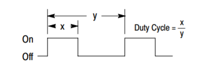
Duty Cycle
The Duty Cycle is a 32-bit value from 0 to 32,000 indicating the relative duty cycle of the output. For example, a value of 8000 would indicate a 25% duty cycle, a value of 16,000 would indicate a 50% duty cycle. 0 turns the output off, 32,000 turns the output on.
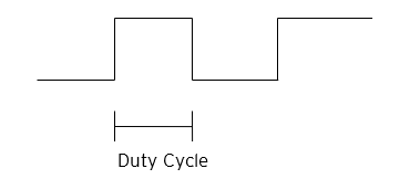
NOTE: The Duty Cycle is the ratio of pulse width to the interval between like portions of successive pulses. Usually expressed as a percentage.
Frequency
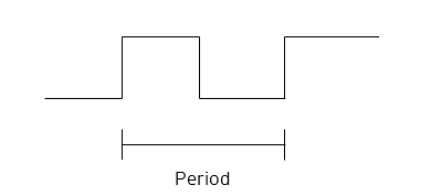
The Frequency is a 32-bit value indicating the output frequency in Hertz. One over the frequency is the period.
At controller power-up or during a download, the PWM![]() Pulse Width Modulation (PWM) - A technique for generating a DC voltage level from a higher constant DC voltage. The constant input voltage is chopped to produce pulses at a constant period and constant amplitude. Modulating the pulse width (duration) controls the average voltage of the output. output is maintained at zero until both the Frequency and the Duty cycle are loaded with non-zero values. When the controller is placed in stop mode, the state of the PWM outputs is dependent on the PWM State on Controller Stop configuration. This configuration allows for either hold-last-state or specific frequency and duty cycle counts. Specifying zero for either the period or duty causes the PWM output to remain low during stop mode.
Pulse Width Modulation (PWM) - A technique for generating a DC voltage level from a higher constant DC voltage. The constant input voltage is chopped to produce pulses at a constant period and constant amplitude. Modulating the pulse width (duration) controls the average voltage of the output. output is maintained at zero until both the Frequency and the Duty cycle are loaded with non-zero values. When the controller is placed in stop mode, the state of the PWM outputs is dependent on the PWM State on Controller Stop configuration. This configuration allows for either hold-last-state or specific frequency and duty cycle counts. Specifying zero for either the period or duty causes the PWM output to remain low during stop mode.
Note: For standard I/O models (Models 3, 4, 5 and 6) the maximum recommended PWM frequency is 10kHz, due to the limitations of built-in output circuitry. The HE-XHSQ generates 24V pulse outputs with a recommended max of 400kHz. The HE-XHSQ-5 generates 5V pulse outputs with a recommended max of 1MHz. The add-on HSQ and HSQ-5 module can be added to the Model 2 unit for HSC function.
PWM Wave Output Form
|
PWM Output Waveform Table |
|
|---|---|
| Rise Time | 150ns Max |
| Fall Time | 150ns Max |
| PWM Period | Frequency = 1 / Period |
High-Speed Counter Match
When either Q1 or Q2 is configured for HSC Output operation, their output state is based on a comparison between the counter accumulator and match registers.
Stepper Function
Most controllers support two stepper functions, one on each high-speed output when in two counter mode. In four counter mode, the controllers support one stepper function.
Step Function - A signal that has a zero (0) value before a certain instant of time and a constant nonzero value immediate after that instant.

The Stepper requires five parameters (%AQ![]() 16-bit output registers used to send analog information such a voltages, levels, or speed settings to an attached device.s) to be set for operation. These parameters may be set at run-time but are ‘latched’ when the stepper is commanded to start:
16-bit output registers used to send analog information such a voltages, levels, or speed settings to an attached device.s) to be set for operation. These parameters may be set at run-time but are ‘latched’ when the stepper is commanded to start:
|
Start Frequency (pulses per second) |
Sets the frequency for the first cycle during the acceleration phase and the frequency of the last cycle during the deceleration phase. When an acceleration or deceleration count is specified, the Start Frequency must be greater than 0 and must not exceed the run frequency or an error is generated. |
|
Run Frequency (pulses per second) |
Sets the frequency for the last cycle during the acceleration phase, the consistent frequency during the run phase, and the frequency of the first cycle during the deceleration mode. The Run Frequency must be greater than 0 and must not exceed 5000Hz (standard), 400,000Hz (HE-XHSQ) or 1.0 MHz (HE-XHSQ-5) |
|
Acceleration Count |
Sets the number of cycles to occur within the acceleration phase. The frequency of the cycles within this mode will vary linearly between the specified Start and Run frequency. The Accel count must not equal 1 or an error is generated. Setting this value to zero disables this phase. |
|
Run Count |
Sets the number of cycles to occur within the run phase. The frequency of the cycles within this mode is constant at the specified Run frequency. The Run count may be any value. Setting this value to zero disables this phase. |
|
Deceleration Count |
Sets the number of cycles to occur within the deceleration phase. The frequency of the cycles within this phase will vary linearly between the specified Run and Stop frequency. The Decel count must not equal 1 or an error is generated. Setting this value to zero disables this phase. |
The stepper provides two Boolean![]() Boolean- [Data Type BOOL] - A single bit, binary value, or register/variable. Boolean points have only two possible values, 'TRUE' or 'FALSE'. registers to provide stepper status:
Boolean- [Data Type BOOL] - A single bit, binary value, or register/variable. Boolean points have only two possible values, 'TRUE' or 'FALSE'. registers to provide stepper status:
|
Ready/Done |
A high indication on this register indicates the stepper sequence can be started (i.e. not currently busy) and also when the move is completed. |
|
Error |
A high indication on this register indicates that one of the analog parameters specified above is invalid or the stepper action was aborted before the operation was complete. This register is cleared on the next start command if the error was corrected. |
The stepper requires one discrete register to control the stepper action. Setting this register starts the stepper cycle. This register must remain set to complete the entire cycle. Clearing this register before the cycle is complete aborts the step sequence and sets the error bit.
Note: Setting the PLC mode to stop while the stepper is in operation causes the stepper output to immediately drop to zero and the current stepper count to be lost.
Note: The stepper output level may cause damage or be incompatible with some motor drive inputs. Consult drive documentation to determine if output level and type is compatible.
High-Speed Output Functions Register Map
The register assignments for the high speed I/O can be moved via a setting in Cscape. The values shown are the DEFAULT values and may not match the same starting point as the values shown below. Refer to the documentation for a specific controller through the Documentation Search on the Horner website. Register Maps are located in the User Manuals.
Return to the Top: High Speed I/O General Overview and Defaults