DeviceNet Communications
See also: Hardware Configuration
Topic Menu
DeviceNet Overview
XL series DeviceNet OCS provides DeviceNet communication on CAN port. It allows an OCS to supervise a DeviceNet network. Up to 63 slave devices can be connected to a Device Net Scanner. Depending on baud rate and the cable type used, the Device Net slave nodes can be located up to 1,500 feet (457.2 meters) from the OCS.
The Device Net Scanner Polled![]() Polled - When a device is consistently asked for data, either as fast as possible or on a time basis. Normally associated with Modbus communications. data is mapped directly into the OCS %I
Polled - When a device is consistently asked for data, either as fast as possible or on a time basis. Normally associated with Modbus communications. data is mapped directly into the OCS %I![]() Single-bit input registers. Typically, an external switch is connected to the registers., %Q
Single-bit input registers. Typically, an external switch is connected to the registers., %Q![]() Single-bit output registers. Typically, these bits are connected to an actuator, indicator light or other physical outputs., %AI
Single-bit output registers. Typically, these bits are connected to an actuator, indicator light or other physical outputs., %AI![]() 16-bit input registers used to gather analog input data such as voltages, temperatures, and speed settings coming from an attached device. and %AQ
16-bit input registers used to gather analog input data such as voltages, temperatures, and speed settings coming from an attached device. and %AQ![]() 16-bit output registers used to send analog information such a voltages, levels, or speed settings to an attached device. registers/variables. When using Polled Messaging, data is read from the OCS %Q and %AQ registers/variables by the Device Net Scanner, formatted into Device Net packets and sent to the Device Net nodes. As data produced by the Device Net slave nodes are received by the Device Net Scanner, it is converted into OCS register/variable notation and stored in the OCS %I and %AI Registers/variables. This happens automatically without the need for any ladder program intervention.
16-bit output registers used to send analog information such a voltages, levels, or speed settings to an attached device. registers/variables. When using Polled Messaging, data is read from the OCS %Q and %AQ registers/variables by the Device Net Scanner, formatted into Device Net packets and sent to the Device Net nodes. As data produced by the Device Net slave nodes are received by the Device Net Scanner, it is converted into OCS register/variable notation and stored in the OCS %I and %AI Registers/variables. This happens automatically without the need for any ladder program intervention.
The Device Net specification provides two methods of establishing communications between a scanner and its nodes. The first method makes use of the “Unconnected Message Manager” (UCMM) and the second is known as “Group 2 Only”. “Group 2 Only” is the simplest, because of its simplicity, many slave devices only support the “Group 2 Only” method. The Device Net Scanner allows both of these methods to be used simultaneously. Any single Device Net slave device can be either a Group 2 Only node or a UCMM node, never both. A Device Net network can be made up of a mixture of “Group 2 Only” and UCMM” slave devices.
Device Net Scanner Features
The Device Net Scanner supports the following features:
-
Baud Rates: 125K, 250K, and 500K,
-
UCMM protocol (Log on),
-
Group 2 Only protocol,
-
The Polled Connection,
-
Ladder Initiated Explicit Messaging (LIEM),
-
Fragmentation on both polled
 Polled - When a device is consistently asked for data, either as fast as possible or on a time basis. Normally associated with Modbus communications. and explicit connections
 -
All four Message Body Formats under UCMM.
Return to the Top: DeviceNet Communications
DeviceNet Technical Specifications
DeviceNet Connector
The Device Net connector consists of a 5- pin removable screw terminal with the following terminal descriptions:
DeviceNet I/O Connector Pinout |
||
|---|---|---|
| Pin | Signal | Description |
| 1 | V- | Power - |
| 2 | CAN_L | Signal - |
| 3 | Ground | Shield |
| 4 | CAN_H | Signal + |
| 5 | V+ | Power + |
Return to the Top: DeviceNet Communications
DeviceNet Configuration
Before configuring or programming a controller, the target controller must be selected using Cscape software. After selecting a controller, it is possible to determine the functions that are available in that specific model, and the controller can also be programmed.
-
An OCS with single CAN port supports CsCAN
Horner APG's proprietary network protocol that runs on the Bosch CAN network specifications. Prior to the advent of the OCS. protocol by default. -
User must change the firmware to support DeviceNet protocol on CAN. See also: Firmware Update
-
OCS with Dual CAN port supports DeviceNet protocol on CAN2.
-
-
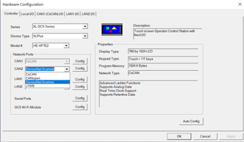
From Home > Program > Hardware Configuration from Cscape tool bar following dialog will appear. See Networking and Communications for more details.
-
Select DeviceNet Scanner and Config.
Network Properties
Once the Config button next to CAN1 or CAN2 is selected, the DeviceNet network configuration utility will open, based on the controller that is selected.
The first dialog that will appear is the Network Properties dialog.
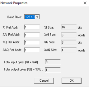
This dialog allows the user to set the starting Reference Addresses of the registers/variables and Baud Rate of the network. The %I![]() Single-bit input registers. Typically, an external switch is connected to the registers. size, %AI
Single-bit input registers. Typically, an external switch is connected to the registers. size, %AI![]() 16-bit input registers used to gather analog input data such as voltages, temperatures, and speed settings coming from an attached device. size, %Q size, %AQ
16-bit input registers used to gather analog input data such as voltages, temperatures, and speed settings coming from an attached device. size, %Q size, %AQ![]() 16-bit output registers used to send analog information such a voltages, levels, or speed settings to an attached device. size, %I Ref Address, %AI Ref Address, %Q Ref Address, and %AQ Ref Address values are values with respect to the OCS that the Device Net Scanner is running on.
16-bit output registers used to send analog information such a voltages, levels, or speed settings to an attached device. size, %I Ref Address, %AI Ref Address, %Q Ref Address, and %AQ Ref Address values are values with respect to the OCS that the Device Net Scanner is running on.
DeviceNet Baud Rate
The user can select any of the 3 supported baud rates, for the given network each slave node has to be set to same baud as that of scanner node. Different nodes at different baud rate cannot communicate with each other.
Note: Using System Menu the user can modify the Baud Rate and Node-ID. But after power reset Node-ID and Baud rate will get set to value configured using Configuration tool.
Return to the Top: DeviceNet Communications
DeviceNet Scanner Configurator
Once configuration in Network properties dialog is completed, click OK. Network view of DeviceNet Configurator will display as below:
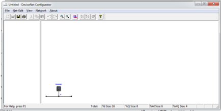
The right pane is the Network View where the user can build a visual representation of a network depicting the XL series DeviceNet Master(scanner) and all slave nodes (devices).
The DeviceNet network can now be constructed within the network view display. Before constructing a network with this utility, it is recommended that user should follow the below steps to create the network:
-
Decide what baud rate the network will run at. This is needed for the Scanner module configuration as well as the configuration of each individual DeviceNet node. All nodes including the Scanner must be configured for the same baud rate.
-
Identify all devices (nodes) that are going to be a part of the network.
-
Check whether Data Assembly information is available for each DeviceNet node in the network. This can be in the form of printed information in the manufacture's manual or in the form of an EDS file provided by the manufacturer. Note that some EDS files do not provide the nodes’ polled consumption and production sizes.
-
Assign MACIDs (node addresses) to each DeviceNet node. The MACIDs assigned to each node is totally arbitrary. The only thing that might have an effect here is the fact that the Scanner actually scans the nodes in order by MACID. Gaps can be left in the MACID assignments to allow for future nodes to be added, if desired. DeviceNet provides for nodes with lower MACIDs to have a higher network priority. The MACID for the Scanner can be assigned any value between 0 to 63. Every node on the network must be assigned a unique MACID.
-
All bit type input data must be assigned to a contiguous block of OCS %I registers/variables/ variables and all word type input data must be assigned to a contiguous block of OCS %AI
16-bit input registers used to gather analog input data such as voltages, temperatures, and speed settings coming from an attached device. registers/variables. -
All bit type output data must be assigned to a contiguous block of OCS
-
%Q
Single-bit output registers. Typically, these bits are connected to an actuator, indicator light or other physical outputs. registers/variables and all word type output data must be assigned to a contiguous block of OCS %AQ registers/variables. -
When these steps are taken, then a visual representation of the network can be constructed within the Network View screen.
-
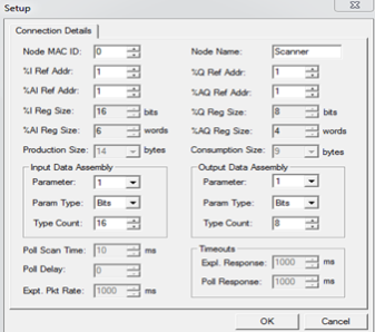
To add a node, either right-click in the right-window pane and select Add New Node or select the Net-Edit > Add New Node menu item. Once a new node is visually added to the display, it can now be configured in the following manner. Double click on the new node and the following screen appears:
-
Node MAC ID: The Node ID
Usually refers to the ID of the device on a supported CAN, such as CsCAN, CANopen, etc. Each device must have a unique network ID. Also called Node ID. of the slave Node. DeviceNet scanner will respond to this address. -
Node Name: Name for the slave Node
-
%I
Single-bit input registers. Typically, an external switch is connected to the registers. Ref Addr: Specifies the first register in the block of OCS %I registers/variables that are assigned to this node. NOTE: This block must be part of the larger block of %I registers/variables assigned to the Device Net Scanner. -
%Q
Single-bit output registers. Typically, these bits are connected to an actuator, indicator light or other physical outputs. Ref Addr: Specifies the first register in the block of OCS %Q registers/variables that are assigned to this node. Note that this block must be part of the larger block of %Q registers/variables assigned to the Device Net Scanner. -
%AI
16-bit input registers used to gather analog input data such as voltages, temperatures, and speed settings coming from an attached device. Ref Addr: Specifies the first register in the block of OCS %AI registers/variables that are assigned to this node. Note that this block must be part of the larger block of %AI registers/variables assigned to the Device Net Scanner. -
%AQ
16-bit output registers used to send analog information such a voltages, levels, or speed settings to an attached device. Ref Addr: Specifies the first register in the block of OCS %AQ registers/variables that are assigned to this node. Note that this block must be part of the larger block of %AQ registers/variables assigned to the Device Net Scanner.-
Note: The Cscape sets the starting reference addresses automatically based on the reference address in scanner, but the user can change them if needed.
-
Note: The Cscape sets the starting reference addresses automatically based on the reference address in scanner, but the user can change them if needed.
-
-
Input Data Assembly/Output Data Assembly - There are four parameters in each assembly. Each parameter can be bit data (bits), word data (words), or nothing (none). This value is set in the parameter type drop down window. The count of each parameter is set in the parameter count drop down box. The parameter drops down box is used to select any of the four available parameters within an assembly for editing/viewing. %I and %AI values come together to form the production size of the node. These are values going from the node onto the network to the Scanner. %Q and %AQ values come together to form the consumption size of the node. These values are coming from Scanner into the node.
Note: Bit data must be in Multiples of 8. See also: Data Assemblies
-
Poll Scan Time
Time required for the controller to read its inputs, solve the Ladder Logic program, and write its outputs. Scan times are usually expressed in milliseconds.
NOTE: Scan times can vary, depending on number and complexity of Ladder Logic rungs that are active during the "solve" portion of the scan.: The minimum amount of time that the Device Net Scanner will wait between sending polled Polled - When a device is consistently asked for data, either as fast as possible or on a time basis. Normally associated with Modbus communications. requests to the node. In effect, this is the minimum time between consecutive scans to the node. Once the system is running, the actual polled scan time can be displayed through the fault table facility in real time. -
Poll Delay Time: Some slave nodes cannot accept fragmented polled
Polled - When a device is consistently asked for data, either as fast as possible or on a time basis. Normally associated with Modbus communications. data packets sent at full speed, especially if the baud rate is 500KB. This entry instructs the Device Net Scanner to insert a delay between polled fragmented packets addressed to this node. For most nodes, this entry should be set to zero. If required, try a value of 100 or 200. -
Expt Pkt Rate: Specifies the Expected Packet Rate that will be loaded into the node when a dialog is established with the node. The node uses this number multiplied by four as an inactivity timer limit value. The node resets the inactivity timer each time it receives a polled request message from the Device Net Scanner. If the timer expires the node will enter the timed-out state, effectively taking itself off-line.
-
Expl (Explicit) Response Time: The maximum time that the Device Net Scanner will wait for an explicit response from the node. If this timer expires, the node is taken off-line. Then at the next opportunity, the Device Net Scanner will attempt to reconnect to the node.
-
Poll Response Time: The maximum time that the Device Net Scanner will wait for a polled response from the node. If this timer expires, the node is taken off-line. Then at the next opportunity, the Device Net Scanner will attempt to reconnect to the node.
The process can then be repeated for another node and so forth until the entire network is done.
Auto Remap
The user can choose Auto Remap feature to reassign the reference address for all nodes. In the DeviceNet Configurator, select Network > Auto Remap to remap the nodes in the network.
Caution: Auto Remap reassigns the reference addresses for all nodes so that no gaps are left in the map. The Auto Remap action cannot be undone and needs to be used with caution.
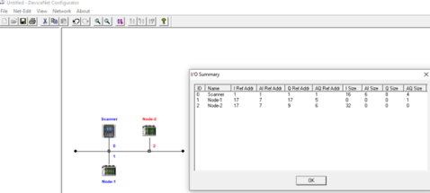
The Network baud rate and register base addresses can be set at any time in the DeviceNet Configurator selecting Network > Properties or by double-clicking anywhere on the screen in the right window pane. This will bring up the Network Properties screen. To see a summary of I/O devices in the DeviceNet Configurator, select Network > I/O Summary. This option is used to display a summary of the inputs ( %I![]() Single-bit input registers. Typically, an external switch is connected to the registers.s and %AI
Single-bit input registers. Typically, an external switch is connected to the registers.s and %AI![]() 16-bit input registers used to gather analog input data such as voltages, temperatures, and speed settings coming from an attached device.s) and outputs (%Q
16-bit input registers used to gather analog input data such as voltages, temperatures, and speed settings coming from an attached device.s) and outputs (%Q![]() Single-bit output registers. Typically, these bits are connected to an actuator, indicator light or other physical outputs.s and %AQ
Single-bit output registers. Typically, these bits are connected to an actuator, indicator light or other physical outputs.s and %AQ![]() 16-bit output registers used to send analog information such a voltages, levels, or speed settings to an attached device.s) of every node on the network configuration. It also displays reference addresses.
16-bit output registers used to send analog information such a voltages, levels, or speed settings to an attached device.s) of every node on the network configuration. It also displays reference addresses.
To zoom the network view in and out in the DeviceNet Configurator, select View > Net – Zoom In or Net – Zoom Out. When done with the configuration utility, click on the close icon (The ‘X’ icon) in the upper right corner of the utility screen. This will close the utility and save the configuration for downloading to the OCS.
Note: The module configuration is stored in the OCS.
Return to the Top: DeviceNet Communications
DeviceNet Data Transfer
Module to OCS Register/Variables Mapping
The DeviceNet Scanner requires the use of four blocks of OCS registers/variables. Using Cscape, the user can specify the starting register/variable and the size of each of these four blocks. Data from the OCS to Device Net nodes are passed in the %Q![]() Single-bit output registers. Typically, these bits are connected to an actuator, indicator light or other physical outputs. and %AQ
Single-bit output registers. Typically, these bits are connected to an actuator, indicator light or other physical outputs. and %AQ![]() 16-bit output registers used to send analog information such a voltages, levels, or speed settings to an attached device. registers/variables. Data to the OCS passed by the Scanner are in the %I
16-bit output registers used to send analog information such a voltages, levels, or speed settings to an attached device. registers/variables. Data to the OCS passed by the Scanner are in the %I![]() Single-bit input registers. Typically, an external switch is connected to the registers. and %AI
Single-bit input registers. Typically, an external switch is connected to the registers. and %AI![]() 16-bit input registers used to gather analog input data such as voltages, temperatures, and speed settings coming from an attached device. registers/variables.
16-bit input registers used to gather analog input data such as voltages, temperatures, and speed settings coming from an attached device. registers/variables.

As per above Network Properties window, the OCS register references are set to value one. This simplifies our examples by assuming that all of the register reference assignments start at value one. That is, the first %I, %Q, %AI and %AQ registers/variables are assigned to OCS register %I1, %Q1, %AI1 and %AQ1. Although these register assignments can be placed anywhere within the OCS register space, we have made these assignments for simplicities sake.
Node to OCS Register/Variables Mapping
Additionally, the DeviceNet Scanner subdivides these register blocks providing individual sub-blocks to each Device Net node. This provides mapping between the OCS data registers/variables and the data to and from each individual Device Net node. As a result, each node’s polled![]() Polled - When a device is consistently asked for data, either as fast as possible or on a time basis. Normally associated with Modbus communications. data is immediately available to the OCS ladder code by accessing the appropriate OCS registers/variables.
Polled - When a device is consistently asked for data, either as fast as possible or on a time basis. Normally associated with Modbus communications. data is immediately available to the OCS ladder code by accessing the appropriate OCS registers/variables.
Message Packets and Fragmentation
A DeviceNet message packet can contain from 0 to 8 bytes of data. If more than 8 bytes of data are required, the message must be broken up into two or more packets or fragments. This is called fragmentation. The DeviceNet Scanner handles this automatically, without any intervention by the user or the ladder program running in the OCS.
Fragmentation works differently for Polled messages than Explicit messages. In the case of Polled messages, each message fragment is sent to the receiving party one after the other as fast as possible. In the case of large Explicit messages, the sender will send only the first packet. The sender then waits for an ACK message from the receiver. Upon receiving the ACK, the sender then transmits the next packet and waits for another ACK. This process repeats until all message fragments have been sent. This ACK process requires a considerable amount of time when compared to Polled messages. See also: Explicit Messaging
Physical Limitations
There are physical limits on the amount of data that can be transferred between the DeviceNet Scanner and the OCS. This limit is 300 bytes of %I![]() Single-bit input registers. Typically, an external switch is connected to the registers. and %AI
Single-bit input registers. Typically, an external switch is connected to the registers. and %AI![]() 16-bit input registers used to gather analog input data such as voltages, temperatures, and speed settings coming from an attached device. data and 300 bytes of %Q
16-bit input registers used to gather analog input data such as voltages, temperatures, and speed settings coming from an attached device. data and 300 bytes of %Q![]() Single-bit output registers. Typically, these bits are connected to an actuator, indicator light or other physical outputs. and %AQ
Single-bit output registers. Typically, these bits are connected to an actuator, indicator light or other physical outputs. and %AQ![]() 16-bit output registers used to send analog information such a voltages, levels, or speed settings to an attached device. data. The smallest data item that DeviceNet can handle is one byte. If an application requires only a single %Q output or command bit, a group of 8 %Qs must be allocated. The remaining 7 will be unused (or wasted). The same is true for bit type input data.
16-bit output registers used to send analog information such a voltages, levels, or speed settings to an attached device. data. The smallest data item that DeviceNet can handle is one byte. If an application requires only a single %Q output or command bit, a group of 8 %Qs must be allocated. The remaining 7 will be unused (or wasted). The same is true for bit type input data.
Data Assemblies
For a Polled![]() Polled - When a device is consistently asked for data, either as fast as possible or on a time basis. Normally associated with Modbus communications. Connection, the data bytes within the DeviceNet messages must be sent and received in a predetermined order. This order is specified by “Data Assemblies”. Data Assemblies are published by the manufacturer of the DeviceNet node. To properly map the DeviceNet data to or from the OCS, the data assemblies for each DeviceNet node must be available and understood. Consult data sheets from the DeviceNet node manufacturer for specific details on Data Assemblies.
Polled - When a device is consistently asked for data, either as fast as possible or on a time basis. Normally associated with Modbus communications. Connection, the data bytes within the DeviceNet messages must be sent and received in a predetermined order. This order is specified by “Data Assemblies”. Data Assemblies are published by the manufacturer of the DeviceNet node. To properly map the DeviceNet data to or from the OCS, the data assemblies for each DeviceNet node must be available and understood. Consult data sheets from the DeviceNet node manufacturer for specific details on Data Assemblies.
From the point of view of the OCS, all input is via %I and %AI registers/variables and all output data is via %Q and %AQ registers/variables. From the point of view of the DeviceNet nodes, all I/O is via streams of data bytes, known as Data Assemblies, that they send and receive. In most DeviceNet nodes, the data assembly formats are fixed, in others they are configurable. Consult data sheets from the DeviceNet node manufacturer for details on Data Assemblies.
The DeviceNet Scanner accepts output data from the OCS in the form of %Q and/or %AQ registers/variables. It then translates this data into DeviceNet polled messages and sends them to the node. The DeviceNet Scanner receives DeviceNet polled response messages from the addressed DeviceNet node, translates these DeviceNet messages and passes the data on to the OCS where they are stored in the appropriate %I and/or %AI registers/variables.
The DeviceNet Scanner allows up to 4 blocks of data to be concatenated to form a data assembly. Each block can be configured as either bit data or word data. The number of bits or words within each block is also configurable. Keep in mind that bits must be assigned in groups of 8 bits. The user can configure, for example, that the first block will contain 32 bits, the second block might contain 7 words, the third block might contain 8 bits and the fourth block might contain 5 words. This would result in a data assembly that contains: 32 bits followed by 7 words followed by 8 bits followed by 5 words. This example results in a data assembly that contains 29 bytes. The user must define a data assembly for both the input and output data for each node on the network.
DeviceNet Nodes
DeviceNet Node Priority and Implications
The DeviceNet Scanner can carry on conversations with several DeviceNet nodes simultaneously. Because of this, DeviceNet Node Priorities become important. Within the scheme of CAN communications, there is a concept known as Arbitration. If two slaves begin to transmit CAN messages simultaneously, the slave with the smallest node address will win. The loser must immediately stop transmitting and try again later. This gives obvious priority to the slave with the lower node address. This can create problems if care is not taken in the assignment of node addresses.
Consideration should be given to the priorities of the individual nodes. In the design of most networks, there are usually a few nodes that require a higher priority than the rest. These nodes should be assigned the lower node addresses.
Fault Table
The DeviceNet Scanner provides a fault table that makes available the status of each node on the network. OCS registers/variables %Q3, %Q4, %Q5, %AI5, and %AI6 (with respect to the base addresses set within the configuration) are used to provide a user interface into the fault table. The table has an entry for each DeviceNet node.
There are three command bits (%Q![]() Single-bit output registers. Typically, these bits are connected to an actuator, indicator light or other physical outputs. registers/variables) to allow control over the fault table and the entry being displayed. Setting %Q3 causes the first node with a fault to be displayed. Setting %Q4 causes the next node with a fault to be displayed. If the node being displayed is the last node with a fault, then the first node with a fault will be displayed. Setting %Q5 causes all entries in the fault table to be cleared. Unpredictable results may occur if more than one of command bit %Q3, %Q4 or %Q5 is simultaneously set.
Single-bit output registers. Typically, these bits are connected to an actuator, indicator light or other physical outputs. registers/variables) to allow control over the fault table and the entry being displayed. Setting %Q3 causes the first node with a fault to be displayed. Setting %Q4 causes the next node with a fault to be displayed. If the node being displayed is the last node with a fault, then the first node with a fault will be displayed. Setting %Q5 causes all entries in the fault table to be cleared. Unpredictable results may occur if more than one of command bit %Q3, %Q4 or %Q5 is simultaneously set.
The user is also provided two %AI registers/variables that are used to display fault information about the indicated node. Each of these registers/variables are broken into two bytes as indicated below:
-
The least significant byte of register %AI5 contains the Node Address of the fault data displayed in the next 3 bytes.
-
The most significant byte of register %AI5 contains the Fault Code that exists for the node indicated by the addressed node. The fault code can have the following values:
-
None.
-
Polled
Polled - When a device is consistently asked for data, either as fast as possible or on a time basis. Normally associated with Modbus communications. Scan Time Time required for the controller to read its inputs, solve the Ladder Logic program, and write its outputs. Scan times are usually expressed in milliseconds.
NOTE: Scan times can vary, depending on number and complexity of Ladder Logic rungs that are active during the "solve" portion of the scan.. -
Timeout waiting for an Explicit Fragmented Acknowledge Response Message.
-
Timeout waiting for an Allocate Explicit Connection Response Message.
-
Timeout waiting for an Allocate Polled connection Response Message.
-
Timeout waiting for a Get Polled Consumption Size Response Message.
-
Timeout waiting for a Get Polled Production Size Response Message.
-
Timeout waiting for a "NOP" Response Message.
-
Timeout waiting for a Polled Response Message.
-
Timeout waiting for a Set Polled Expected Packet Rate Response Message.
-
Timeout waiting for any other Explicit Response Message.
-
Unable to Establish an Explicit Connection.
-
Unable to Establish a Polled Connection.
-
Polled Consumption Size Error.
-
Polled Production Size Error.
There are priorities involved with the fault code values. Priorities are assigned based on the numeric value of the individual fault codes. A higher number has a higher priority. If a code of 5 (Timeout waiting for a Get Polled Consumption Size Response Message) is being displayed, a lower priority code such as 2 (Timeout waiting for an Explicit Fragmented Acknowledge Response Message) will not displace the higher priority code. However, a lower priority fault code will be displaced by a higher priority code occurring.
Fault code type 1 (Polled Scan Time) is really not a fault at all. Instead, if there is nothing else that needs to be displayed, The Polled scan time is displayed. This is the time from one Polled Command Message to the next, NOT the node's response time to a Polled Command Message. When looking at these polled scan times, keep in mind that the DeviceNet Scanner will overlap Polled Command Messages. In other words, while waiting for a Polled Response Message from one node, a Polled Command Message will be sent to another node. It is possible on smaller networks that there could be a simultaneous Polled Response Message pending from each and every node on the network. The primary purpose of this technique is to more fully utilize the DeviceNet bandwidth.
The most significant byte of register %AI6 contains Fault Data Byte 1. This byte takes on different meanings depending on the fault code:
-
If the fault code is Polled Consumption Size Error, this entry displays the consumption size as reported by the specified node.
-
If the fault code is Polled Production Size Error, this entry displays the production size as reported by the specified node.
-
If the fault code is Polled Scan Time, both bytes of this word (16-bit WORD value) reports the actual polled scan time for this node in milliseconds.
The least significant byte of register %AI6 contains Fault Data Byte 2. This byte takes on different meanings depending on the fault code:
-
If fault code is Polled Consumption Size Error, this entry displays the consumption size as indicated by the Scanner configuration file for the specified node.
-
If fault code is Polled Production Size Error, this entry displays the production size as indicated by the Scanner configuration file for the specified node.
-
If the fault code is Polled Scan Time, both bytes of this word (16-bit WORD value) reports the actual polled scan time for this node.
Because it is possible that higher priority faults can be generated during system power up sequences, the following sequence should be followed to access the fault table:
-
Allow the system to run for a few seconds.
-
Clear the fault table.
-
Wait a few more seconds.
-
And finally, access the fault table.
This causes the fault table to be refreshed with current data. Any preexisting high priority entries are eliminated in favor of the current lower priority data.
Return to the Top: DeviceNet Communications
DeviceNet Scanner Registers
It requires a number of OCS registers/variables to be assigned to itself. The following tables define the Scanner register requirements and definitions of these data assemblies (These registers/variables are with respect to the base addresses assigned within the configuration):
DeviceNet Scanner %Q
|
|
|---|---|
| %Q1 | Stop DeviceNet Scanning |
| %Q2 | Send Explicit Message |
| %Q3 | Display the first node with a fault |
| %Q4 | Display the next node with a fault |
| %Q5 | Clear all faults |
| %Q6-8 | Reserved |
DeviceNet Scanner %AQ
|
|
|---|---|
| %AQ1 | Transmit Buffer First %R |
| %AQ2 | Transmit Buffer Size (In bytes) |
| %AQ3 | Receive Buffer First %R Number |
| %AQ4 | Receive Buffer Size (In bytes) |
DeviceNet Scanner %I
|
|
|---|---|
| %I1 | Someone is Offline |
| %I2 | DeviceNet scanning is stopped |
| %I3 | Explicit Transaction Complete |
| %I4 | Explicit Error – Buffer Allocation Error |
| %I5 | Explicit Error – Can’t get %R buffer from OCS |
| %I6 | Explicit Error – Invalid MAC ID |
| %I7 | Explicit Error – Node Not Configured |
| %I8 | Explicit Error – Node not on-line |
| %I9 | Explicit Error – Operation timed out |
| %I10 | Explicit Error – Other DNT Error |
| %I11 | Explicit Error – Receive Buffer Overrun |
| %I12 | Explicit Error – Cannot put %R buffer to OCS |
| %I13-16 | Reserved |
DeviceNet Scanner %AI
|
|
|---|---|
| %AI1 | Online status, nodes 0-15 |
| %AI2 | Online status, nodes 16-31 |
| %AI3 | Online status, nodes 32-47 |
| %AI4 | [Online status, nodes 48-63] |
| %AI5 LSB | [Fault Table Bytes 1 – Node Address] |
| %AI5 MSB | Fault Table Bytes 2 – Fault Code |
| %AI6 LSB | Fault Table Bytes 3 |
| %AI6 MSB | Fault Table Bytes 4 |
DeviceNet Register Definitions
%Q1 Stop Device Net Scanning - Setting this bit causes the Device Net Scanner to close or release all connections between itself and all Device Net nodes. No further communications will occur between the Scanner and the Device Net nodes until the Stop Device Net Scanning bit is cleared. While the Device Net Scanning is Stopped; Bit %I2 bit will be set.
%Q3 Display the first node with a fault - Displays the fault data for the lowest addressed node that has an entry in the fault table.
%Q4 Display the next node with a fault - Displays the next node
%Q5 Clear all fault codes - Clears all entries in the fault table.
%I1 Someone is Offline - This status bit indicated that one or more configured nodes are not online.
%I2 Device Net Scanning is Stopped - This status bit indicates that the Device Net scanning is stopped as a result of the bit having been set by the OCS.
%AI1 - %AI4 - The following four %AI registers/variables collectively contain 64 individual status bits:
-
%AI1 Online Status of Nodes 00 – 15
-
%AI2 Online Status of Nodes 16 – 31
-
%AI3 Online Status of Nodes 32 – 47
-
%AI4 Online Status of Nodes 48 - 63
-
One bit is assigned to each of the 64 possible DeviceNet node addresses. Status bits for nodes 0 through 15 are mapped into the first %AI register. Status bits for nodes 16 through 31 are mapped into the second %AI register. Status bits for nodes 32 through 47 are mapped into the third %AI register. Status bits for nodes 48 through 63 are mapped into the fourth %AI register. The status bit for node 0 is placed in the least significant bit position of the first %AI register, with consecutively higher addressed nodes status bits being placed in the next higher bit positions.
-
Each individual status bit is set TRUE if the corresponding DeviceNet node is Online. Online is defined as the node’s Polled connection being in the Established state and the node is communicating Polled data.
%AI5 LSB – Fault Table Byte 1 – Node Address - This byte contains the node address of the fault data displayed in the next 3 bytes.
Note: Many Device Net nodes also provide additional diagnostic data within their individual data assemblies.
Return to the Top: DeviceNet Communications
Explicit Messaging
The Scanner supports both POLLED and EXPLICIT connections. Explicit Messaging requires a great deal of overhead in both the Scanner and the OCS. Multiple OCS scans may be required to access the required data between the OCS and the Scanner. As a result, Explicit Messages should be reserved for access to infrequently needed data, such as configuration or tuning parameters only.
The sequence below presents a general description of the process that must be executed to service an Explicit request:
-
The ladder code builds an explicit request message in a group of %R
Retentive 16-bit registers. registers/variable. -
The ladder code plugs the start of and length of the transmit and receive buffers into four
-
%AQ
16-bit output registers used to send analog information such a voltages, levels, or speed settings to an attached device. registers/variables. The transmit and receive buffers must both be located in the %R register space of the OCS. -
The ladder code then sets the “Send Explicit Message” command bit.
-
The Scanner periodically checks the “Send Explicit Message” command bit.
-
If the “Send Explicit Message” command bit is set, processing of the explicit request begins. This command bit must remain on until success or error status is returned.
-
The four %AQ registers/variables are examined and checked for validity.
-
The Scanner requests the OCS
-
to send the transmit buffer.
-
The Scanner then checks the MACID contained in the transmit buffer. Several checks take place, MACID out-of-range, referenced node not configured and referenced node not On- line.
-
Then the message is formatted and sent to the referenced node.
-
When the response message is received, a check is made to see if the allocated receive buffer is large enough to accept the response message.
-
The message is then sent to the block of %R
Retentive 16-bit registers. registers/variables designated as the receive buffer. -
The Explicit Transaction Complete bit is then set.
-
If there were any errors detected in any of the previous steps, the process is aborted and the appropriate error status bit along with the Explicit Transaction Complete bit are set.
Building Explicit Messages
Example 1
In the following example, let’s assume that we want to read the polled consumption size from the node at MACID 3, we also want to locate the transmit buffer at %R101, the receive buffer at %R51 and we will also allocate 20 bytes to the receive buffer.
|
Byte Number |
Register Number |
Description |
Transmit Buffer Data |
|---|---|---|---|
| 0 | R101 LSB | MACID (Node Address) | 03 |
| 1 | R101 MSB | Service Code (Get Attribute Single) | 14 |
| 2 | R102 LSB | Class ID (Connection Class) | 05 |
| 3 | R102 MSB | 00 | |
| 4 | R103 LSB | Instance ID (Polled Connection) | 02 |
| 5 | R103 MSB | 00 | |
| 6 | R104 LSB | Attribute # (Consumption Size) | 07 |
| Register | Description | Value |
|---|---|---|
| %AQ1 | Start of Transmit Buffer | 101 |
| %AQ2 | Number of Bytes to Transmit | 7 |
| %AQ3 | Start of Receive Buffer | 51 |
| %AQ4 | Receive Buffer Allocation Size | 20 |
Example 2
In the following example we want to write the polled expected packet rate to the node at MACID 3, we also want to locate the transmit buffer at %R101, the receive buffer at %R51, we will also allocate 20 bytes to the receive buffer.
|
Byte Number |
Register Number |
Description |
Transmit Buffer Data |
|---|---|---|---|
| 0 | R101 LSB | MACID (Node Address) | 03 |
| 1 | R101 MSB | Service Code (Set Attribute Single) | 16 |
| 2 | R102 LSB | Class ID (Connection Class) | 05 |
| 3 | R102 MSB | 00 | |
| 4 | R103 LSB | Instance ID (Polled Connection) | 02 |
| 5 | R103 MSB | 00 | |
| 6 | R104 LSB | Attribute (Expected Packet Rate) | 07 |
| 7 | R104 MSB | Data Value Low Byte | E8(Hex) |
| 8 | R105 LSB | Data Value High Byte | 03 |
| Register | Description | Value |
|---|---|---|
| %AQ1 | Start of Transmit Buffer | 101 |
| %AQ2 | Number of Bytes to Transmit | 7 |
| %AQ3 | Start of Receive Buffer | 51 |
| %AQ4 | Receive Buffer Allocation Size | 20 |
How to Interpret Explicit Response Messages
The normal, expected response from an Explicit Message is the Acknowledge Message: nsmit buffer at %R101, the receive buffer at %R51, we will also allocate 20 bytes to the receive buffer.
|
Byte Number |
Description |
Transmit Buffer Data |
|---|---|---|
| 0 | Number of bytes received | Xx |
| 1 | Xx | |
| 2 | MACID | 01 |
| 3 | *Service Code | 0x90(Hex) |
| 4 | Optional Data | Xx |
| - | Optional Data | Xx |
| - | Optional Data | Xx |
| n | Optional Data | Xx |
| *Previous sent Service Code (0x10) + 0x80 |
Note: The Most Significant Bit in the Service Code byte is used as a Response Bit indicating that the command was properly received. [Service Code 0x10 + Response Bit 0x80 = 0x90]. If any extra data needs to be returned, that data will be placed into subsequent bytes.
Note: The number of bytes received value is the number of bytes of the message placed in the receive buffer including the two bytes devoted to the number of bytes received.
Explicit Message Errors
In the case that an Explicit Message requests a function that cannot be performed by the referenced node, an Explicit Error Message will be returned.
An Explicit Error Message takes the following form:
| Explicit Error Message | ||||
|---|---|---|---|---|
| Byte Number | Description |
Ex. Values |
Word Offset |
Values (from example) |
| 0 | No. of bytes received | 06 | %R1 | 0006 |
| 1 | 00 | |||
| 2 | MACID | 01 | %R2 | 0x9401 |
| 3 | Service Code | 94 | ||
| 4 | General Error Code | xx | %R3 | xxxx |
| 5 | Additional Error Code | xx | ||
An Error is indicated by a 0x94 in the service code byte. This indicates that the referenced node has detected an error and the two bytes following indicate the specifics to that error. The next byte indicates the General Error Code. The last byte contains an Additional Error Code to indicate additional information. See appendix C for a list of and definitions of General and Additional Error Codes.
Many DeviceNet manufactures have defined vendor specific error codes. In this case the General error code will be in the range of 0xD0 to 0xFF (Vendor-specific Object and Class errors). In these cases, the Additional error code can be anything. Consult the documentation from the node manufacture for more details.
Return to the Top: DeviceNet Communications