EtherNet/IP Scanner Help File
See also: Get Started with Cscape
Introduction to EtherNet/IP Scanner
Enabling EtherNet/IP Scanner in Cscape
Enabling EtherNet/IP Scanner in Cscape
EtherNet/IP Adapter Configuration - Adapter Tab
EtherNet/IP Adapter Configuration - Input Tab
EtherNet/IP Adapter Configuration - Input Tab
EtherNet/IP Adapter Configuration - ConfigTab
EtherNet/IP Adapter Configuration - Explicit Message Tab
Status Register Expected Behavior & Troubleshooting
Topic Menu
Introduction to EtherNet/IP Scanner
EtherNet/IP is an industrial EtherNet IP protocol widely used for real-time communication between PLCs and devices such as remote I/O modules, VFDs, servo drives, and other controllers.
In EtherNet/IP communication:
-
A scanner actively initiates and manages connections
-
An Adapter responds to the scanner and exchanges data
The EtherNet/IP Scanner in OCS allows the OCS controllers to act as a master (scanner) and establish implicit (cyclic) I/O connections with EtherNet/IP Adapter devices on the network.
Return to the Top: EtherNet/IP Scanner Help File
Enabling EtherNet/IP Scanner in Cscape
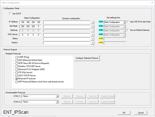
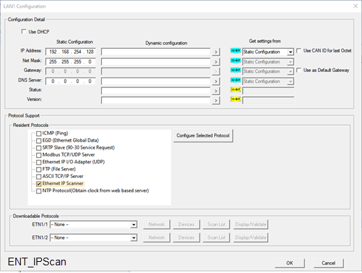
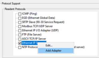
EtherNet/IP Scanner is configured under LAN Configuration as a Resident Protocol.
Use the following path to navigate to the LAN Configuration screen: Hardware Configuration > LAN Configuration > Resident Protocols
Note: Alternately, the Ethernet/IP Scanner configuration window can be opened by Edit or double-click.
Return to the Top: EtherNet/IP Scanner Help File
Enabling EtherNet/IP Scanner - Resident Protocol Configuration
-
Enable the Scanner Protocol
Note: This action enables the EtherNet/IP Scanner service in the OCS firmware.
-
Navigate to the Resident Protocols screen.
-
In the Resident Protocols section, locate EtherNet/IP Scanner and select it.
IMPORTANT: Checking the box is not sufficient. Mandatory configuration is also required.
-
-
Open the Scanner Configuration
-
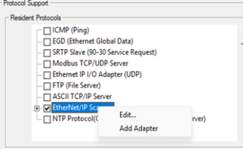
From the Resident Protocols area, right-click the EtherNet/IP Scanner option, and from the pop-up menu, select Edit. The EtherNet/IP Scanner Configuration window will open.
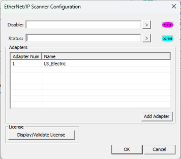
Note: The EtherNet/IP Scanner Configuration window contains two mandatory fields:
-
Disable: Disable Bit, supports BOOLEAN only
-
Status: Status Register, supports 32-Bit only
-
-
-
Complete the EtherNet/IP Configuration window.

-
Configure the Disable Bit and Status Register fields.
Important: If these fields are not configured, the EtherNet/IP Scanner will not work, even though they might be enabled and/or Adapters are configured.
-
Disable (Bit): Permits the application logic to enable or disable the EtherNet/IP Scanner at runtime.
-
Set Disable (Bit) = 0 → Scanner is Enabled
-
Set Disable (Bit) = 1 → Scanner is Disabled
-
-
Status (Register): Provides runtime diagnostic information about the EtherNet/IP Scanner.
-
Status (Bits) 1-8 = Number of Adapters connected
-
Status (Bits) 9-32 = Reserved for future use
-
-
-
Configure the Adapters: Displays all EtherNet/IP Adapter devices currently configured in the scanner
The following Adapter information may be available depending on option and screen:
-
Adapter Num → Unique Adapter identification number
-
Name → User-configured Adapter name
-
Newly added Adapters
-
Previously configured existing Adapters
Adapter Options
Right-click on any Adapter from the Adapter list to access the following options:
-
Edit:
-
Opens the EtherNet/IP Scanner – Adapter Configuration window for the selected Adapter.
-
Modifies the Adapter configuration settings.
-
-
Delete Adapter
-
Removes the selected Adapter from the EtherNet/IP Scanner configuration list.
-
-
Add Adapter:
-
Used when adding a new EtherNet/IP Adapter device that the OCS scanner will communicate with.
-
Each Adapter added represents one EtherNet/IP target device on the network
-
-
License (section): Applies and validates the EtherNet/IP Scanner license.
Note: XL Prime Series ONLY:
-
EtherNet/IP Scanner requires a valid license on the XL Prime series controllers.
-
Click Display/Validate License to apply or validate the license.
Note: Canvas Series ONLY:
-
EtherNet/IP Scanner support is enabled by default.
-
No separate EtherNet/IP Scanner license is required for Canvas models.
-
-
-
-
Adding an EtherNet I/P Adapter Device
Use the following steps to add an EtherNet/IP Adapter device (such as a VFD, remote I/O, or drive) with which OCS scanner will communicate. Each Adapter added represents one EtherNet/IP target device on the network.
Note: A maximum 32 Adapters can be configured.
-
From the Resident Protocols area, right-click the EtherNet/IP Scanner option, and from the pop-up menu, select Add Adapter. The EtherNet/IP Scanner - Adapter Configuration window open.
-
Return to the Top: EtherNet/IP Scanner Help File
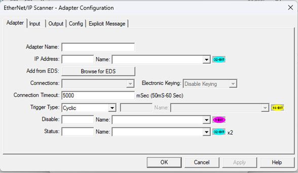
EtherNet/IP Adapter Configuration - Adapter Tab
Use the following steps to configure the Adapter tab. The Adapter tab is used to configure the basic communication parameters required for the OCS EtherNet/IP Scanner to establish Implicit Messaging/Explicit Messaging with an EtherNet/IP Adapter device.
-
Each Adapter configured here represents one EtherNet/IP target device on the network.
Adapter Name
Adapter Name: Logical name used to identify the Adapter inside the OCS project.
-
Best Practices: Use names that clearly indicate the device type and location to help during debugging, maintenance, and multi-device projects.
-
Enter a meaningful name (e.g., PowerFlex_525, RemotelO_Station1)
Return to the Top: EtherNet/IP Scanner Help File
IP Address
IP Address: Specifies the network address of the EtherNet/IP Adapter device.
-
Both static and dynamic IPs are accepted:
-
Static IP: Enter a constant IP address directly.
-
Dynamic IP (by variable):
-
Assigns a 32-Bit register / variable
-
Allows the IP address to be changed at runtime through logic or HMI.
-
-
-
The Adapter IP must be reachable from the OCS LAN interface.
-
Dynamic IP assignment is useful when:
-
Device IPs are set through logic or from graphics screen.
-
Multiple identical systems are deployed.
-
Return to the Top: EtherNet/IP Scanner Help File
Add from EDS
Add from EDS: Imports EtherNet/IP device information from an EDS (Electronic Data Sheet) file.
This function:
-
Reviews the confirmation pop-up for accuracy in vendor name, product type, and product name.
-
Automatically populates supported connection definitions and assembly information (used in later tabs).
-
Reduces manual configuration errors.
-
Select Browse for EDS to select an EDS file. A confirmation pop-up will open.
This confirmation ensures the correct Adapter EDS has been imported.
Return to the Top: EtherNet/IP Scanner Help File
Connections
Connections: Selects the EtherNet/IP connection type supported by the Adapter.
This function:
-
Provides a dropdown list that contains all connection types defined in the imported EDS file.
-
Includes available options that depend entirely on Adapter capability and EDS definition.
Note: The selected connection must match the device’s expected I/O configuration. And, the incorrect connection selection can lead to forward open failure and data size mismatch errors.
Return to the Top: EtherNet/IP Scanner Help File
Connection Timout
Connection Timeout: Defines the maximum time the scanner waits for valid I/O data before declaring a connection failure.
Configuration Options
-
Static Value
-
Default connection timeout value is 5 seconds.
-
Timeout value can be modified manually based on application requirements.
-
-
Dynamic Value
Assign a 16-Bit register / variable to change timeout at runtime.
Note: If the program is downloaded with the Connection Timeout configured as dynamic, the assigned variable value will initially be 0 after download. In this condition, the scanner automatically considers the default timeout value as 5 seconds. The timeout value can later be updated based on application requirements.
Supported Range
-
50 milliseconds to 60 seconds
Usage Notes
-
Increase timeout for devices with slow start up and networks with higher latency.
-
Shorter timeout permits faster fault detection
Return to the Top: EtherNet/IP Scanner Help File
Trigger Type
Trigger Type: Defines how and when implicit I/O data exchange is triggered.
Available Trigger Types
-
Cyclic: Data is exchanged continuously based on RPI.
-
Change-Of-State (COS): Data updates only when a change occurs.
-
Application: Triggered by the application logic.
-
Dynamic Config: Trigger behavior defined dynamically via configuration.
Typical Usage
Cyclic trigger type is the most commonly used mode for drives, remote I/O, and real-time control devices.
Return to the Top: EtherNet/IP Scanner Help File
Disable (Bit)
Disable (Bit): Permits the application to disable communication with this specific Adapter.
Configuration:
Disable Bit: Assigns a Boolean variable or register
Behavior:
-
0 → Adapter communication enabled.
-
1 → Adapter communication disabled.
Usage:
Disables only the selected Adapter without affecting other EtherNet/IP connections
Return to the Top: EtherNet/IP Scanner Help File
Status (Register)
Status Register: Provides status information related to implicit messaging for this Adapter.
Notes:
-
This status register is specific to implicit messaging
-
It is used for monitoring Adapter communication state and errors
-
Detailed status Bit definitions are provided separately
| Status Bits | Status Name | Status Description |
| 1 | Implicit Connection Established | Implicit Messaging Connection is established |
| 2 | Implicit Connecting | Implicit Messaging Connecting |
| 3 | Invalid Configuration | Invalid Implicit Messaging Configuration |
| 4 | Bind Error | Socket Bind Error |
| 5 | Connection Timeout | Timeout during connection establishment with Adapter |
| 6 | Response Timeout | No response from Adapter |
| 7 | Transmit Buffer Error | Buffer allocation failed during transmit` |
| 8 | Transmit Error | Unable to transmit data |
| 9 | Structure Fail | Structure Allocation Fail |
| 10-16 | Unused Bits | Reserved for future use |
| 17-24 | CIP Status Codes | Volume 1: Common Industrial Protocol Specification, Appendix B: Status Codes |
| 25-32 | Additional Status Words | Number of additional Status Words |
| 33-48 | Extended Status | Vol. 1: Common Industrial Protocol Specification, Chapter 3: Communication Object Classes |
| 49-64 | Additional Status for Certain Error Codes | Additional Status word required for specific error codes |
Note: In case of any errors, refer to troubleshooting section.
Return to the Top: EtherNet/IP Scanner Help File
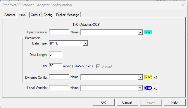
EtherNet/IP Adapter Configuration - Input Tab
The Input tab defines how input (Adapter → OCS) data is received from the EtherNet/IP Adapter to the OCS using implicit messaging. This tab mainly controls the following:
-
Input Assembly Instance
-
Input data format and size
-
Requested Packet Interval (RPI)
-
Unicast communication
-
Optional dynamic configuration from logic or HMI
Return to the Top: EtherNet/IP Scanner Help File
Input Instance
Input Instance: Specifies the Input Assembly Instance number used by the EtherNet/IP Adapter.
Behavior based on EDS import
-
If EDS file is imported
-
The Input Instance field becomes hidden
-
Assembly instance is automatically taken from the EDS definition
-
Manual configuration is not required
-
-
If EDS file is NOT imported
-
The Input Instance field remains visible
-
User must manually enter the input assembly value
-
The value must match one of the assemblies supported by the Adapter
-
Configuration Options
-
Enter a constant value matching the Adapter’s supported input assemblies
-
Assign a 16-Bit variable/register to configure the Input Instance dynamically from logic and HMI.
Return to the Top: EtherNet/IP Scanner Help File
EtherNet/IP Scanner - Input Tab - Parameters Section
Parameters: Defines how input data is formatted and how often it is updated.
Return to the Top: EtherNet/IP Scanner Help File
Data Type
Data Type: Defines the data type of the input assembly data.
Behavior
-
The dropdown lists all supported data types.
-
Available options are shown in the configuration window
Supported Data Types
-
BOOL
-
BYTE
-
INT
-
UINT
-
DINT
-
UDINT
-
REAL
-
LREAL
Usage
-
Must match the Adapter’s supported input data format
-
Incorrect data type selection can cause data interpretation issues
Return to the Top: EtherNet/IP Scanner Help File
Data Length
Data Length: Specifies the length of the input data.
Behavior
-
If EDS file is imported, the Data Length is auto-filled based on the EDS definition.
-
If EDS file is NOT imported, the user can enter the value manually.
Note: Data length must match the Adapter’s actual input data size definition in the EDS
Return to the Top: EtherNet/IP Scanner Help File
Requested Packet Interval (RPI)
RPI: Defines how often input data is sent from the Adapter to the OCS.
Behavior
-
If EDS file specifies a default RPI, RPI is auto-filled from the EDS.
-
If the EDS file does NOT specific RPI, Cscape sets a default value of 50ms
Supported Range
-
50 milliseconds to 60 seconds.
User Control
-
RPI value can be changed manually
-
The Adapter must support the configured RPI value
Key Points
-
Smaller RPI → faster updates, higher network load
-
Larger RPI → slower updates, lower network load
Return to the Top: EtherNet/IP Scanner Help File
Unicast Checkbox
What is Unicast:
-
Adapter sends data directly to a single scanner
-
Uses point-to-point communication
-
Reduces unnecessary network traffic
Unicast Checkbox Behavior:
-
Checked → Unicast communication
Key Points
-
The Unicast option is selectable only if the Adapter EDS supports both modes.
-
Selection should be based on network design and application needs.
Return to the Top: EtherNet/IP Scanner Help File
Dynamic Config
Dynamic Config: Permits the input parameters to be configured dynamically at runtime from logic or HMI.
Parameters Controlled Dynamically
-
Data Type
-
Data Length
-
RPI
-
Unicast
Configuration
-
Assign a base 16-Bit register or variable
-
Four consecutive 16-Bit locations are used automatically
Configuration Example: Register-Based Programs
If Dynamic Config is assigned to %R1001, then:
|
Register |
Function |
|---|---|
| %R1001 | Datatype |
| %R1002 | Data length |
| %R1003 | RPI |
| %R1004 | Unicast(value 1) |
Configuration Example: Variable-Based, IEC & Enhanced IEC Programs
If Dynamic Config is assigned to a variable array:
Note: The array length must be 4.
|
Input Parameters Dynamic |
Variable Array |
|---|---|
| Input_Parameters_dynamic[0] | Data Type |
| Input_Parameters_dynamic[1] | Data Length |
| Input_Parameters_dynamic[2] | RPI |
| Input_Parameters_dynamic[3] | Unicast(value 1) |
Datatype Mapping for Dynamic Configuration
| Data Type | Value | Size |
|---|---|---|
| BOOL | 0 | 1-Bit |
| BYTE | 1 | 8-Bit |
| INT | 2 | 16-Bit |
| UINT | 3 | 16-Bit |
| DINT | 4 | 32-Bit |
| UDINT | 5 | 32-Bit |
| REAL | 6 | 32-Bit |
| LREAL | 7 | 64-Bit |
UI Behavior
After Dynamic Config is assigned, the following are "greyed out," as values are now controlled dynamically.
-
Data type
-
Data Length
-
RPI
-
Unicast Checkbox
Return to the Top: EtherNet/IP Scanner Help File
Local Variable
Local Variable: Defines where the input data received from the Adapter is stored in the OCS.
Configuration
-
Assign a register or variable
-
The variable type and size depends on the selected Data Type and the configured Data Length
Behavior
-
Input data from Adapter to OCS is mapped into this variable
-
Data is interpreted based on the configured parameters
Special case – Dynamic Configuration
-
When Parameters are set dynamically, the local variable is forced to a 16-Bit register array with a maximum length of 256, since the data format is determined dynamically.
-
Permits logic to interpret data dynamically based on runtime configuration
Return to the Top: EtherNet/IP Scanner Help File
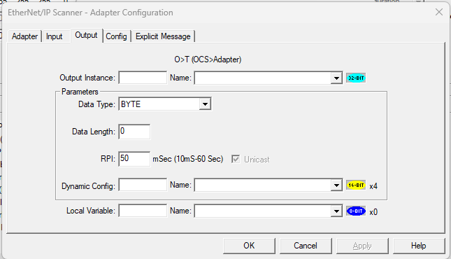
EtherNet/IP Adapter Configuration - Output Tab
The Output tab is used to configure the cyclic output data that is sent from the OCS to the Ethernet/IP Adapter.
This tab mainly controls the following:
-
Output Assembly Instance
-
Output data format and size
-
Requested Packet Interval (RPI)
-
Unicast communication
-
Optional dynamic configuration from logic or HMI
Return to the Top: EtherNet/IP Scanner Help File
Output Instance
Output Instance: Specifies the Output Assembly Instance number used by the EtherNet/IP Adapter.
Behavior based on EDS Import
-
If the EDS file is imported
-
The Output Instance field becomes hidden
-
Assembly instance is automatically taken from the EDS definition
-
Manual configuration is not required
-
-
If the EDS file is NOT imported
-
The Output Instance field remains visible
-
The User must manually enter the output assembly value
-
The value must match one of the assemblies supported by the Adapter
-
Configuration Options
-
Enter a constant value matching the Adapter’s supported output assemblies
-
Assign a 16-Bit variable/register to configure the Output Instance dynamically from Logic and HMI
Return to the Top: EtherNet/IP Scanner Help File
Parameters Section
Parameters Section: Defines how input data is formatted and how often it is updated.
Return to the Top: EtherNet/IP Scanner Help File
Data Types
Data Types: Defines the data type of the output assembly data.
Behavior
-
The dropdown lists all supported data types
-
Available options are shown in the configuration window
Supported Data Types
-
BOOL
-
BYTE
-
INT
-
UINT
-
DINT
-
UDINT
-
REAL
-
LREAL
Usage
-
Must match the Adapter’s supported output data format
-
Incorrect data type selection can cause data interpretation issues
Return to the Top: EtherNet/IP Scanner Help File
Data Length
Data Length: Specifies the length of the output data.
Behavior
Note: The Data Length must match the Adapter’s actual output data size definition in the EDS
-
If the EDS file is imported, the Data Length is auto-filled based on the EDS definition
-
If the EDS file is NOT imported, the user can enter the value manually.
Return to the Top: EtherNet/IP Scanner Help File
Requested Packet Interval (RPI)
RPI: Defines how often output data is sent from the OCS to the Adapter.
Behavior
-
If the EDS file is imported, the RPI is auto-filled based on the EDS definition
-
If the EDS file is NOT imported, Cscape sets a default value of 50ms.
Supported Range
50 milliseconds to 60 seconds
User Control
-
RPI value can be changed manually
-
The Adapter must support the configured RPI value
Smaller vs Larger RPI
-
Smaller RPI → faster updates, higher network load
-
Larger RPI → slower updates, lower network load
Return to the Top: EtherNet/IP Scanner Help File
Unicast Checkbox
What is Unicast
-
Adapter sends data directly to a single scanner
-
Uses point-to-point communication
-
Reduces unnecessary network traffic
Behavior
-
Checked → Unicast communication
Key Points
-
The Unicast option is selectable only if the Adapter EDS supports.
-
Selection should be based on network design and application needs.
Return to the Top: EtherNet/IP Scanner Help File
Parameters Dynamic Config
Parameters Dynamic Config: Permits the Output parameters to be configured dynamically at runtime from logic or HMI.
Parameters Controlled Dynamically
Data Type
Data Length
RPI
Unicast selection
Configuration
-
Assign a base 16-Bit register or variable
-
Four consecutive 16-Bit locations are used automatically
Configuration Example: Register-Based programs
If Dynamic Config is assigned to %R2001, then:
|
Register |
Function |
|---|---|
| %R2001 | Data Type |
| %R2002 | Data Length |
| %R2003 | RPI |
| %R2004 | Unicast(value 1) |
Configuration Example: Variable-Based, IEC & Enhanced IEC Programs
If Dynamic Config is assigned to a variable array:
Note: The array length must be 4.
|
Output Parameters Dynamic |
Variable Array |
|---|---|
| Output_Parameters_dynamic[0] | Data Type |
| Output_Parameters_dynamic[1] | Data Length |
| Output_Parameters_dynamic[2] | RPI |
| Output_Parameters_dynamic[3] | Unicast(value 1) |
Datatype Mapping for Dynamic Configuration
| Data Type | Value | Size |
|---|---|---|
| BOOL | 0 | 1-Bit |
| BYTE | 1 | 8-Bit |
| INT | 2 | 16-Bit |
| UINT | 3 | 16-Bit |
| DINT | 4 | 32-Bit |
| UDINT | 5 | 32-Bit |
| REAL | 6 | 32-Bit |
| LREAL | 7 | 64-Bit |
UI Behavior
After Dynamic Config is assigned, the following are "greyed out," as values are now controlled dynamically.
-
Data Type
-
Data Length
-
RPI
-
Unicast Checkbox
Return to the Top: EtherNet/IP Scanner Help File
Local Variable
Local Variable: Defines the output data that needs to be sent from the OCS to the Adapter.
Configuration
-
Assign a register or variable
-
The variable type and size depending on the selected Data Type and the configured Data Length.
Behavior
-
Output data from OCS to Adapter is mapped into this variable
-
Data is interpreted based on the configured parameters
Dynamic Configuration Special Case
-
When Parameters are set dynamically, the local variable is forced to a 16-Bit register array with a maximum length of 256, since the data format is determined dynamically.
-
This permits the logic to interpret data dynamically based on runtime configuration.
Return to the Top: EtherNet/IP Scanner Help File
EtherNet/IP Adapter Configuration - ConfigTab
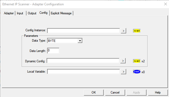
In EtherNet/IP, the Config Assembly is used to send configuration data to an Adapter during connection establishment. Only Adapters that explicitly support a Config Assembly (and expose it in their EDS file) can use this feature. If the Adapter does not support a Config Assembly or the EDS file does not define it, the Config tab will have no effect even if values are entered manually.
Return to the Top: EtherNet/IP Scanner Help File
Config Instance
-
If the EDS file is imported using Add from EDS (provided the Adapter supports a Config Assembly), the Config Instance field becomes invisible.
-
If NO EDS file is imported, this field remains visible, and the user may then:
-
Enter the Config Assembly instance as a constant value, based on what the Adapter supports.
-
Assign a 16-Bit register/variable to set the Config Instance dynamically from logic or HMI.
-
Return to the Top: EtherNet/IP Scanner Help File
Parameters Section
Parameters Section: Defines how config data is formatted and how often it is updated.
Return to the Top: EtherNet/IP Scanner Help File
Data Type
Behavior
-
The dropdown lists all supported data types
-
Available options are shown in the configuration window
Supported Data Types
-
BOOL
-
BYTE
-
INT
-
UINT
-
DINT
-
UDINT
-
REAL
-
LREAL
Usage
-
Must match the Adapter’s supported config data format
-
Incorrect data type selection can cause data interpretation issues
Return to the Top: EtherNet/IP Scanner Help File
Data Length
Data Length: Specifies the length of the Config data.
Behavior
Note: The Data Length must match the Adapter’s config assembly size definition in the EDS.
-
If the EDS file is imported, the Data Length is auto-filled based on the EDS definition.
-
If the EDS file is not imported, the user can enter the value manually.
Return to the Top: EtherNet/IP Scanner Help File
Parameters Dynamic Config
Parameters Dynamic Config: Permits the Output parameters to be configured dynamically at runtime from logic or HMI.
Parameters Controlled Dynamically
-
Data Type
-
Data Length
Configuration
-
Assign a base 16-Bit register or variable
-
Two consecutive 16-Bit locations are used automatically
Configuration Example: Register-Based programs
If the Dynamic Config is assigned to %R3001
|
Register |
Function |
|---|---|
| %R3001 | Data Type |
| %R3002 | Data Length |
Configuration Example: Variable-Based, IEC & Enhanced IEC Programs
If Dynamic Config is assigned to a variable array:
Note: The array length must be 2.
|
Config Parameters Dynamic |
Variable Array |
|---|---|
| Config_Parameters_dynamic[0] | Data Type |
| Config_Parameters_dynamic[1] | Data Length |
Datatype Mapping for Dynamic Configuration
| Data Type | Value | Size |
|---|---|---|
| BOOL | 0 | 1-Bit |
| BYTE | 1 | 8-Bit |
| INT | 2 | 16-Bit |
| UINT | 3 | 16-Bit |
| DINT | 4 | 32-Bit |
| UDINT | 5 | 32-Bit |
| REAL | 6 | 32-Bit |
| LREAL | 7 | 64-Bit |
Return to the Top: EtherNet/IP Scanner Help File
Local Variable
The Local Variable holds the Config data exchanged between the OCS and the Adapter, based on the configured parameters.
Note: A Local Variable/Register must be assigned to store the Config Assembly data.
-
The variable/register type is determined by the selected Data Type and Data Length.
-
If the Dynamic Config is enabled, the local variable is forced to a 16-Bit register array with a maximum length of 256, since the data format is determined dynamically.
Return to the Top: EtherNet/IP Scanner Help File
EtherNet/IP Adapter Configuration - Explicit Message Tab
In EtherNet/IP, communication is divided into implicit and explicit messaging. While implicit messaging is used for continuous, cyclic I/O data exchange between the controller and Adapter, explicit messaging is used for on-demand communication. Explicit messaging follows a request/response model, meaning data is exchanged only when triggered by the logic. It is typically used for reading or writing device parameters, accessing object attributes, performing diagnostics, or executing specific services supported by the Adapter. Unlike implicit messaging, it is not time-critical and does not use cyclic RPI-based transmission.
Explicit Messaging is used for the following:
-
Reading device parameters
-
Writing configuration values
-
Accessing object attributes
-
Performing diagnostics
-
Triggering device-specific services
Key Characteristics
-
Request/Response based communication
-
Non-cyclic (not continuous)
-
Triggered from logic
-
Uses object model addressing
Required Addressing Information - Explicit Messaging Operates Using...
These parameters are defined in the Adapter’s object model and are usually available in the device documentation.
-
Class ID
-
Instance ID
-
Attribute ID
-
Service Code (e.g., Read, Write)
Return to the Top: EtherNet/IP Scanner Help File
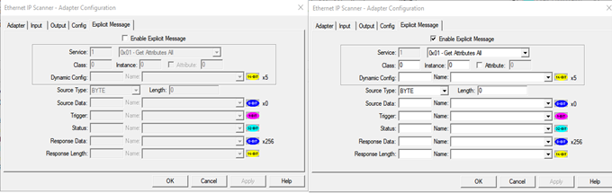
Enable Explicit Messages Checkbox
The Enable Explicit Message checkbox must be selected in order to use explicit messaging functionality.
-
By default, explicit messaging is disabled.
-
When the checkbox is unchecked, all explicit message configuration fields remain inactive (greyed out).
-
When the checkbox is checked, explicit messaging is enabled and all related configuration fields become active, allowing the user to configure:
-
Service
-
Class
-
Instance
-
Attribute
-
Dynamic Configuration
-
Source and Response parameters
-
Explicit messaging operates in a request/response mode, as and when required the trigger Bit must set high to the send the message. The trigger Bit will remain high after successfully sending the message, it must be made low and triggered again to send the next message when parameter access or device-level communication is required.
Once enabled, the user can configure the necessary addressing and data parameters based on the Adapter’s object model and supported services.
Return to the Top: EtherNet/IP Scanner Help File
Service Types
The Service dropdown defines the type of explicit message that will be sent to the Adapter.
-
The dropdown lists all supported EtherNet/IP service types.
-
When a predefined service is selected, the Service code field is automatically filled and becomes read-only (greyed out).
-
When Custom is selected:
-
The Service field becomes editable
-
The user must manually enter the required service code.
-
This allows standard services to be selected easily while still providing flexibility for vendor-specific or advanced services.
Available Service Types
Notes:
-
The selected service must be supported by the Adapter.
-
Required Class, Instance, and Attribute values depend on the selected service.
-
These values are typically defined in the device manual or object model documentation.
| Dropdown Menu Option | Description |
|---|---|
| 0x01 – Get Attributes All |
|
| 0x02 – Set Attributes All |
|
| 0x05 – Reset |
|
| 0x06 – Start |
|
| 0x07 – Stop |
|
| 0x08 – Create |
|
| 0x09 – Delete |
|
| 0x0E – Get Attribute Single |
|
| 0x10 – Set Attribute Single |
|
| Custom |
|
Return to the Top: EtherNet/IP Scanner Help File
Class, Instance & Attribute Configuration
In explicit messaging, the Class, Instance, and Attribute fields define the exact object and parameter inside the Adapter that the message will access.
These values must be entered based on the following:
-
The Adapter’s supported object model
-
Information provided in the device manual
In explicit messaging, the Class, Instance, and Attribute fields define the exact object and parameter inside the Adapter that the message will access. These values must be entered based on:
Class
-
Identifies the object type (for example, Identity Object, Assembly Object, etc.).
-
The user must enter a valid Class ID supported by the Adapter.
Instance
-
Identifies a specific instance of the selected Class.
-
The value must match an instance supported by the device.
Attribute
-
Identifies a specific parameter within the selected Class and Instance.
-
The Attribute field remains greyed out by default.
-
It becomes editable only when the Attribute checkbox is selected.
-
If the checkbox is:
-
Checked → Attribute value can be entered.
-
Unchecked → Attribute field remains disabled and is not used in the message.
-
This design ensures that the Attribute field is only used when required (for example, in Get Attribute Single or Set Attribute Single services).
Return to the Top: EtherNet/IP Scanner Help File
Dynamic Configuration
Dynamic Configuration: The Dynamic Config field allows the following parameters to be set dynamically from logic or HMI:
-
Service
-
Class
-
Instance
-
Attribute enable/disable
-
Attribute value
When a 16-Bit register or variable is assigned to the Dynamic Config field:
-
In Register-based programs, it consumes five consecutive 16-Bit registers.
-
In Variable-based / IEC / Enhanced IEC programs, it requires a variable array with a length of 5.
Once Dynamic Config is assigned:
-
Manual entry of Service, Class, Instance, and Attribute is overridden.
-
Values are taken from the assigned registers/variables.
Configuration Example: Register-Based Programs
If Dynamic Config is assigned to %R3501, then:
|
Register |
Function |
|---|---|
| %R3501 | Service Value |
| %R3502 | Class |
| %R3503 | Instance |
| %R3504 |
Attribute enable flag
|
| %R3505 | Attribute Value |
Configuration Example: Variable-Based
If %R3501 is assigned in the Dynamic Config field:
|
Input Parameters Dynamic |
Variable Array |
|---|---|
| Explicit_Parameters_dynamic[0] | Service |
| Explicit_Parameters_dynamic[1] | Class |
| Explicit_Parameters_dynamic[2] | Instance |
| Explicit_Parameters_dynamic[3] | Attribute enable flag |
| Explicit_Parameters_dynamic[4] | Attribute value |
This structure allows full control of explicit message addressing directly from logic or HMI, making it flexible for advanced or runtime-configurable applications.
Return to the Top: EtherNet/IP Scanner Help File
Source Type and Length
The Source Type defines the data format of the message being sent to the Adapter (for example, when using Set Attribute Single, Set Attribute All & Custom).
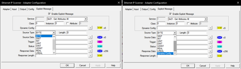
Supported Data Types
-
BOOL
-
BYTE
-
SINT
-
INT
-
UINT
-
DINT
-
UDINT
-
REAL
-
LREAL
-
Dynamic Config
The user must select the Source Data Type based on the parameter being written and the format supported by the Adapter.
Status Configuration (Manual Selection)
When a standard data type (BYTE, INT, DINT, etc.) is selected:
-
The Length field must be set according to the required data size.
-
The Length represents the total data size to be transmitted.
The system automatically adjusts the Length when the data type changes.
Example:
-
If Source Type = BYTE and Length = 8
→ Total data size = 8 bytes
If the data type is changed:
-
INT (16-Bit) → Length automatically becomes 4
-
DINT (32-Bit) → Length automatically becomes 2
This ensures the total byte size remains consistent.
Configuration Example: Register-Based Programs
If Dynamic Config is assigned to %R3601, then:
|
Register |
Function |
|---|---|
| %R3601 | Source Data type Value |
| %R3602 | Source Length |
The Source Data Type must be written using the following mapping:
| Data Type | Value | Size |
|---|---|---|
| BOOL | 0 | 1-Bit |
| BYTE | 1 | 8-Bit |
| INT | 2 | 16-Bit |
| UINT | 3 | 16-Bit |
| DINT | 4 | 32-Bit |
| UDINT | 5 | 32-Bit |
| REAL | 6 | 32-Bit |
| LREAL | 7 | 64-Bit |
Configuration Example: Variable-Based / IEC / Enhanced IEC
If Explicit_Source_Dynamic[] is assigned:
|
Input Parameters Dynamic |
Variable Array |
|---|---|
| Explicit_Parameters_dynamic[0] | Source Data Type (numeric value from table above) |
| Explicit_Parameters_dynamic[1] | Source Length |
This permits the source data format and size to be modified at runtime through logic or HMI.
Return to the Top: EtherNet/IP Scanner Help File
Source Data
Source Data: Assigns the register or variable that contains the actual data to be transmitted in the explicit message.
-
The expected data size and length displayed next to the Source Data field automatically changes based on the Source Data Type selected in the dropdown.
-
The register or variable assigned in this field must match the selected data type.
For example:
-
If Source Type = INT, the assigned variable must be of INT type.
-
If Source Type = DINT, the assigned variable must be of DINT type.
-
-
The size indicator helps the user verify that the correct variable type and length are configured.
Behavior in Static Configuration
When a fixed (non-dynamic) Source Type is selected:
-
The expected data size displayed is calculated based on:
-
Selected Data Type
-
Configured Length
-
-
Any change in data type automatically updates the expected size shown next to the field.
This ensures proper alignment between:
-
Selected Data Type
-
Length
-
Assigned Variable /Register
Behavior in Dynamic Configuration
When Source Type is set to Dynamic Config:
-
The expected data size shown next to the Source Data field defaults to: 16-Bit × 256 (maximum)
-
This is because the actual data type and length will be determined at runtime.
-
In this case, the assigned register/variable must be capable of handling the maximum possible size.
This ensures sufficient memory allocation when the format is being controlled dynamically from logic or HMI.
Return to the Top: EtherNet/IP Scanner Help File
Trigger
Trigger: Initiates the explicit messaging request.
This field must be configured with a BOOLEAN register or variable. When this Bit transitions to HIGH (1), the configured explicit request is sent to the Adapter. The transmission of the explicit message depends entirely on this trigger signal, meaning the request will not be executed unless the trigger Bit is set.
-
Must be configured with a BOOLEAN register/variable.
-
When the Bit becomes HIGH (1), the explicit request is sent.
-
Acts as the execution control for explicit communication.
-
No explicit message will be transmitted unless the trigger is activated.
Return to the Top: EtherNet/IP Scanner Help File
Status
The Status field is dedicated exclusively to monitoring the status of the explicit messaging transaction. This field must be configured with a 32-Bit register or variable. Each Bit within this 32-Bit value represents a specific execution state, success condition, or error related to the explicit request.
Detailed status Bit definitions are provided separately below-
| Status Bits | Status Name | Status Description |
|---|---|---|
| Bit 1 | Explicit Messaging Completed | Explicit Messaging is completed |
| Bit 2 | Explicit Messaging Started | Explicit Messaging Started |
| Bit 3 | Invalid Configuration | Invalid Explicit Messaging Configuration |
| Bit 4 | Bind Error | Socket Bind error |
| Bit 5 | Connection Timeout | Timeout during connection establishment with Adapter |
| Bit 6 | Response Timeout | No response from Adapter |
| Bit 7 | Transmit Buffer Error | Buffer allocation failed during transmit |
| Bit 8 | Transmit Error | Unable to transmit data |
|
Bit 9 |
Structure Fail | Structure allocation fail |
| Bit 10-16 | Unused Bits | Reserved for future use |
| Bit 17-24 | CIP Status Codes | See: “Volume 1: Common Industrial Protocol Specification, Appendix B: Status Codes” |
| Bit 25-32 | Additional Status Size | Number of additional status bytes (Additional bytes will be part of response buffer) |
Return to the Top: EtherNet/IP Scanner Help File
Response Data
Response Data: Stores the data received from the Adapter after an explicit request is executed. This field must be assigned to a register or variable capable of handling up to 8-Bit × 256 elements. The response returned by services such as Get Attribute Single, Get Attribute All, or Custom services will be stored in this assigned register/variable area.
Return to the Top: EtherNet/IP Scanner Help File
Response Length
Response Length: Indicates the total amount of response data received from the Adapter. This field must be configured with a 16-Bit register/variable. It displays the total response received in terms of data length, including the number of characters returned in the explicit response.
Return to the Top: EtherNet/IP Scanner Help File
Status Register Expected Behavior & Troubleshooting
Implicit Messaging
Expected Behavior
| Status Bits | Status Name | Expected Behavior |
|---|---|---|
| Bit 1 | Implicit Connection Established | Bit turns HIGH once the implicit communication is successfully established. |
| Bit 2 | Implicit Connecting |
|
Return to the Top: EtherNet/IP Scanner Help File
Troubleshooting
| Status Bits | Status Name | Potential Issue |
Try This... |
|---|---|---|---|
| Bit 2 | Implicit Connecting |
If the Bit remains HIGH continuously, implicit communication is not being established. |
|
| Bit 3 | Invalid Configuration | If the Bit turns HIGH when the downloaded implicit configuration has any invalid parameters configured. |
|
| Bit 4 | Bind Error | Contact Technical Support for further assistance. | |
| Bit 5 | Connection Timeout | The Bit turns HIGH when no response is received from the Adapter. |
|
| Bit 6 | Response Timeout | The Bit turns HIGH when no response is received from the Adapter. |
Confirm the Adapter side configuration. See: Input Instance |
| Bit 7 | Transmit Buffer Error | Contact Technical Support for further assistance. | |
| Bit 8 | Transmit Error | Contact Technical Support for further assistance. | |
| Bit 9 | Structure Fail | Contact Technical Support for further assistance. | |
| Bit 10-16 | Unused Bits | Reserved (for future use) | |
| Bit 17-24 | CIP Status Codes | See: Volume 1: Common Industrial Protocol Specification, Appendix B: Status Codes | |
| Bit 25-32 | Additional Status Words | Number of additional status words. | |
| Bit 33-48 | Extended Status | Vol. 1: Common Industrial Protocol Specification, Chapter 3: Communication Object Classes. |
Return to the Top: EtherNet/IP Scanner Help File
Explicit Messaging
Expected Behavior
| Status Bits | Status Name | Expected Behavior |
|---|---|---|
| Bit 1 | Explicit Messaging Completed |
Bit turns HIGH once the explicit messaging is successful after triggering the explicit request. |
| Bit 2 | Explicit Messaging Started |
|
Return to the Top: EtherNet/IP Scanner Help File
Troubleshooting
| Status Bits | Status Name | Potential Issue |
Try This... |
|---|---|---|---|
| Bit 2 | Explicit Messaging Started | If the Bit remains HIGH continuously after triggering the explicit request, then explicit communication is not getting established |
|
| Bit 3 | Invalid Configuration | If the Bit turns HIGH when the downloaded Explicit configuration has any invalid parameters configured. Check the provided options in the Cscape program. |
|
| Bit 4 | Bind Error | Contact Technical Support for further assistance. | |
| Bit 5 | Connection Timeout | The Bit turns HIGH when there is a connection timeout. |
|
| Bit 6 | Response Timeout | The Bit turns HIGH when no response is received from the Adapter. |
Confirm the Adapter side configuration. See: IP Address |
| Bit 7 | Transmit Buffer Error | Contact Technical Support for further assistance. | |
| Bit 8 | Transmit Error | Contact Technical Support for further assistance. | |
| Bit 9 | Structure Fail | Contact Technical Support for further assistance. | |
| Bit 10-16 | Unused Bits | Reserved (for future use) | |
| Bit 17-24 | CIP Status Codes | See: Volume 1: Common Industrial Protocol Specification, Appendix B: Status Codes |
Return to the Top: EtherNet/IP Scanner Help File