Serial Modbus Master in Advanced Ladder 
See also: Serial Communication in Advanced Ladder
See also: Project Toolbox for Advanced Ladder
Note: Modbus Master functionality in OCS products has been made much easier with the Protocol Configuration . Though it is still possible to use this programming function, it is recommended to instead use the Protocol Configuration unless the required flexibility cannot be achieved therein.
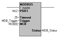
The Modbus Master Communications function can be used to make the OCS controller available as a Modbus Slave over a serial connection. This function must be used in conjunction with the Open Communication Port function [see: Serial Communication in Advanced Ladder], which must open the port for either the Modbus RTU or Modbus ASCII protocol prior to using the Modbus Master Communications function. Operation is achieved by building Message Control Blocks (MCBs) in variables/registers for each message needed, then feeding them through the Modbus Master function. Sequencing of this process is dependent on additional logic.
Note: For variable-based programming, it is required to map variables to registers for the Modbus Master function to know where to read data to or write data from. See Words 5 and 6 of the MCB for more information.
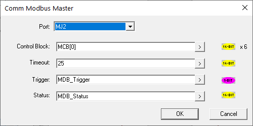
Port: The port to use as a Modbus Master, having previously been opened with the Open Communication Port function. [See: Serial Communication in Advanced Ladder.]
Control Block: A group of six consecutive array elements or registers that comprise the message to be sent when the function is triggered, aka Message Control Block (MCB).
Timeout: A constant value or variable/register that determines how long to wait for a response before considering it a failed message attempt due to no response. Value is in 100ms resolution, i.e. 25 = 2.5s.
Trigger: A 1-bit variable/register that, along with power to the function being present, will trigger the message in the MCB buffer to execute when transitioning from OFF to ON.
Status: A variable/register that will contain the status of the function.
Operation: A message control block is constructed and placed in the Control Block location in this order:
-
Word 1: Slave ID, value from 1 to 247 indicating the target device of this message
-
Word 2: Modbus Command; see Supported Commands below
-
Word 3: Slave Offset, the address in the slave device to access.
-
Word 4: Data Length, how many elements to read or write, up to 125 Words or up to 2000 Boolean
 Boolean- [Data Type BOOL] - A single bit, binary value, or register/variable. Boolean points have only two possible values, 'TRUE' or 'FALSE'. points
 -
Word 5: OCS Reference Type, the type of register to use for this message’s data; see Reference Type below
-
Word 6: OCS Reference Offset, a number which, along with Word 5, determines where in the OCS register memory to read data to or write data from.
When building the MCB, the Modbus Command and Slave Offset are considered “Low Level” designations and work together to determine the “conventional” 5-digit Modbus Address. The Slave Offset is also a 0-based offset instead of 1-based. Some experimentation during development is generally required to match these parameters to the slave device documentation and operation.
-
OK passes power when both this function and the associated open function block is Enabled
-
STATUS is a WORD (16-bit) register used to hold the results of the element.
Status Bit Assignment:
|
Bit # |
Status |
|---|---|
| 1 | Request Succeeded (OK) |
| 2 | Request Failed (See additional errors below) |
| 3 | MCB - ID out of range |
| 4 | MCB - Length exceeds Modbus frame |
| 5 | MCB - Command not supported |
| 6 | MCB - Invalid controller reference |
| 7 | Reserved |
| 8 | Reserved |
| 9 | RX - Timeout Expired |
| 10 | RX - Frame or parity error |
| 11 | RX - Invalid checksum / crc from slave |
| 12 | FX - Invalid format from slave |
| 13 | RSP - Slave rejected the command |
| 14 | RSP - Slave rejected the address |
| 15 | RSP - slave rejected the data |
| 16 | RSP - Slave device error |
This function passes power flow if the associated port is opened and ready for communications.
Translation between Conventional and Low-Level command/address
|
Conventional Address |
Operation |
Slave Command |
Slave Offset |
|
00001 |
Read |
Read Coil Status (1) |
0 |
|
|
Write |
Force Multiple Coils (15) |
0 |
|
10001 |
Read |
Read Input Status (2) |
0 |
|
|
Write |
(not supported by MODBUS) |
0 |
|
30001 |
Read |
Read Input Register (4) |
0 |
|
|
Write |
(not supported by MODBUS) |
0 |
|
40001 |
Read |
Read Holding Register (3) |
0 |
|
|
Write |
Preset Multiple Registers (16) |
0 |
For example, a Modbus slave device with documentation indicating the needed parameter is at Modbus address 43001 (such as an OCS Modbus Slave’s %R1 register reference), the Modbus Command would be 8 and the Slave Offset would be 3000.
| Supported Commands | ||
|
Slave Command |
ID |
Data Type |
|
Read Coil Status |
1 |
|
|
Read Input Status |
2 |
Boolean |
|
Read Holding Register |
3 |
Word |
|
Read Input Register |
4 |
Word |
|
Force Single Coil |
5 |
Boolean |
|
Preset Single Register |
6 |
Word |
|
Read Exception Status |
7 |
Boolean |
|
Loop-Back Diagnostics |
8 |
Word |
|
Force Multiple Coils |
15 |
Boolean |
|
Preset Multiple Registers |
16 |
Word |
|
Get Slave Address |
65 |
Word |
Read Exception Status command - This command is used to read the exception status of a slave. The request must specify a Slave Offset of zero and a Data Length of 8. The response is loaded to memory reference specified by controller Memory Type and Offset fields.
Loop-back diagnostics command - This command is used to read status information and provide limited control of the MODBUS interface for a slave. The request must specify the diagnostic code in the Slave Offset field and a Data Length of 1. Passed and received values are stored in the memory reference specified by controller Memory Type and Offset fields.
Get Slave Address command (Exception Message) - This command is used to establish the Id of a calling slave in modem applications. This is a Horner specific command, which must be supported by the slave devices when this feature is used. The ladder application typically detects a connection through the Modem function block and builds the MCB to broadcast the Get Slave Id command. The Slave Address, Slave Offset, and Data Length fields of the MCB are ignored. Once complete the single word response is stored in the location specified by the controller Memory Type and Offset fields and contains the address of the calling station. Refer to Modbus Slave function block for more information on the format of this command. See also: Serial Modbus Slave in Advanced Ladder
OCS Reference Type - The following values are used in Word 5 of the MCB to specify the type of register to use for the message at hand.
|
Memory Reference |
Ref. Id |
Ref. Type |
|
2 |
word |
|
|
%AIG |
4 |
word |
|
%AQG |
6 |
word |
|
8 |
word |
|
|
10 |
word |
|
|
12 |
word |
|
|
24 |
boolean |
|
|
26 |
boolean |
|
|
%IG |
66 |
boolean |
|
%QG |
68 |
boolean |
|
%I |
70 |
boolean |
|
72 |
boolean |
|
|
74 |
boolean |
|
|
76 |
boolean |
Return to the Top: Serial Modbus Master in Advanced Ladder