Toshiba TOSVERT Protocol
See also: Help for Serial Protocols
Overview
The Toshiba TOSVERT serial downloadable protocol is for communication between the Toshiba drives and an OCS. This is a Master/Slave protocol.
CSCAPE Configuration
To configure OCS for the Toshiba TOSVERT serial protocol, select the Protocol Configuration from the Program menu in Cscape software. Select the appropriate protocol type on the desired port. To make sure that the Software is able to configure the equipment for the correct protocol, make sure ToshibaTosvert.dll file is in the Protocols directory of the current working/open Cscape.
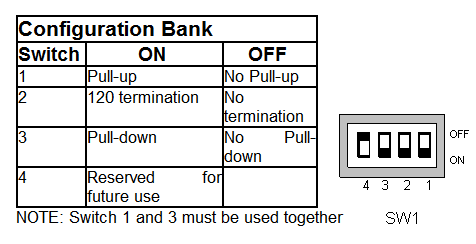
Serial Port Configuration
The default link settings for the terminal are: 9600 baud, 8 data bits, Even parity, 1 stop bit, No handshaking and RS232 communications mode. For communications, the connector may be wired as RS232 or RS485.
Operation By Communications
When enabled, operation by communication takes priority over all other methods. Although the command mode parameter (CMOD) assigns priority to the panel or the terminal block, and the frequency mode parameter (FMOD) assigns priority to the panel, speed potentiometer, or terminal block, communications can take priority over these settings.
To give communications the highest priority for commands, bit 15 of communication number FA00 must be set to 1. Bit 14 of FA00 must be set to 1 to give priority to the frequency setting by communication. Once either of these bits is set, they remain in effect until they are turned off by writing 0’s to them, disconnecting the inverter from the power, resetting the inverter after a trip, or doing a reset to factory setting (tYP).
While bit 15 is set, the command mode parameter (CMOD) is ignored.
Address Mapping for OCS and Supported Functions
ToshibaTosvert.dll supports the following addressing modes:
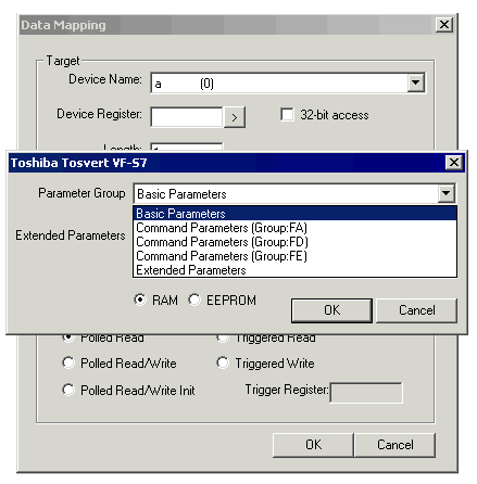
Parameter Specification
Parameters are grouped into several blocks of Basic, Extended, Command, Frequency Monitoring and State Monitoring Parameters.
Basic Parameters (Group No. 00)
Four Navigation Functions
|
Communication No. |
Function |
|
- |
History function |
|
0000 |
Automatic acceleration/ deceleration |
|
0001 |
Torque boost setting macro function |
Basic Parameters
|
Communication No. |
Function |
|
0003 |
Command mode selection |
|
0004 |
Frequency setting mode selection 1 |
|
0005 |
Meter selection |
|
0006 |
Meter adjustment |
|
0007 |
Default setting |
|
0008 |
Forward/reverse run selection (Operation panel) |
|
0009 |
Acceleration time 1 |
|
0010 |
Deceleration time 1 |
|
0011 |
Maximum frequency |
|
0012 |
Upper limit frequency |
|
0013 |
Lower limit frequency |
|
0014 |
Base frequency 1 |
|
0015 |
V/F control mode selection |
|
0016 |
Torque boost value 1 |
|
0017 |
Electronic-thermal protection characteristic selection *2 |
|
0018 |
Preset-speed operation frequency 1 |
|
0019 |
Preset-speed operation frequency 2 |
|
0020 |
Preset-speed operation frequency 3 |
|
0021 |
Preset-speed operation frequency 4 |
|
0022 |
Preset-speed operation frequency 5 |
|
0023 |
Preset-speed operation frequency 6 |
|
0024 |
Preset-speed operation frequency 7 |
Sub-Group of Extended Parameters
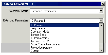
Input/Output Parameters 1
|
Communication No. |
Function |
|
0100 |
Low-speed signal output frequency |
|
0101 |
Speed reach setting frequency |
|
0102 |
Speed reach detection band |
|
0105 |
Priority selection (Both F-CC and R-CC are ON) |
|
0108 |
Always active function selection 1 |
|
0109 |
Analog/contact input function selection (VIA/ VIB terminal) |
|
0110 |
Always-active function selection 2 |
|
0111 |
Input terminal selection 1 (F) |
|
0112 |
Input terminal selection 2 (R) |
|
0113 |
Input terminal selection 3 (RES) |
|
0114 |
Input terminal selection 4 (S1) |
|
0115 |
Input terminal selection 5 (S2) |
|
0116 |
Input terminal selection 6 (S3) |
|
0117 |
Input terminal selection 7 ( VIB) |
|
0118 |
Input terminal selection 8 (VIA) |
|
0130 |
Output terminal selection 1A ( RY-RC) |
|
0131 |
Output terminal selection 2A (OUT-NO) |
|
0132 |
Output terminal selection 3 (FL) |
|
0137 |
Output terminal selection 1B ( RY-RC) |
|
0138 |
Output terminal selection 2B (OUT-NO) |
|
0139 |
Output terminal logic selection ( RY-RC, OUT-NO) |
|
0167 |
Frequency command agreement detection range |
|
0170 |
Base frequency 2 |
|
0171 |
Base frequency voltage 2 |
|
0172 |
Torque boost value 2 |
|
0173 |
Motor electronic-thermal protection level 2 |
|
0185 |
Stall prevention level 2 |
Frequency Parameters
|
Communication No. |
Function |
|
0200 |
Frequency priority selection |
|
0201 |
VIA input point 1 setting |
|
0202 |
VIA input point 1 frequency |
|
0203 |
VIA input point 2 setting |
|
0204 |
VIA input point 2 frequency |
|
0207 |
Frequency setting mode selection 2 |
|
0210 |
VIB input point 1 setting |
|
0211 |
VIB input point 1 frequency |
|
0212 |
VIB input point 2 setting |
|
0213 |
VIB input point 2 frequency |
|
0240 |
Starting frequency setting |
|
0241 |
Operation starting frequency |
|
0242 |
Operation starting frequency hysteresis |
|
0250 |
DC braking starting frequency |
|
0251 |
DC braking current |
|
0252 |
DC braking time |
|
0254 |
Motor shaft fixing control |
|
0256 |
Time limit for lower-limit frequency operation |
|
0260 |
Jog run frequency |
|
0261 |
Jog run stopping pattern |
|
0262 |
Panel jog run operation mode |
|
0264 |
Input from external contacts -UP response time |
|
0265 |
Input from external contacts -UP frequency step width |
|
0266 |
Input from external contacts -DOWN response time |
|
0267 |
Input from external contacts - DOWN frequency step width |
|
0268 |
Initial value of UP/DOWN frequency |
|
0269 |
Saving of changed value of UP/DOWN frequency |
|
0270 |
Jump frequency 1 |
|
0271 |
Jumping width 1 |
|
0272 |
Jump frequency 2 |
|
0273 |
Jumping width 2 |
|
0274 |
Jump frequency 3 |
|
0275 |
Jumping width 3 |
|
0287 |
Preset-speed operation frequency 8 |
|
0288 |
Preset-speed operation frequency 9 |
|
0289 |
Preset-speed operation frequency 10 |
|
0290 |
Preset-speed operation frequency 11 |
|
0291 |
Preset-speed operation frequency 12 |
|
0292 |
Preset-speed operation frequency 13 |
|
0293 |
Preset-speed operation frequency 14 |
|
0294 |
Preset-speed operation frequency 15 (Fire-speed) |
Operation Mode Parameters
|
Communication No. |
Function |
|
0300 |
PWM carrier frequency |
|
0301 |
Auto-restart control selection |
|
0302 |
Regenerative power ride-through control (Deceleration stop) |
|
0303 |
Retry selection (number of times) |
|
0304 |
Dynamic braking selection |
|
0305 |
Overvoltage limit operation (Slowdown stop mode selection) |
|
0307 |
Supply voltage correction (limitation of output voltage) |
|
0308 |
Dynamic braking resistance |
|
0309 |
Dynamic braking resistor capacity |
|
0311 |
Reverse-run prohibition |
|
0312 |
Random mode |
|
0316 |
Carrier frequency control mode selection |
|
0320 |
Droop gain |
|
0323 |
Droop insensitive torque band |
|
0342 |
Braking mode selection |
|
0343 |
Release frequency |
|
0344 |
Release time |
|
0345 |
Creeping frequency |
|
0346 |
Creeping time |
|
0359 |
PID control waiting time |
|
0360 |
PID control |
|
0362 |
Proportional gain |
|
0363 |
Integral gain |
|
0366 |
Differential gain |
Torque Boost Parameters 1
|
Communication No. |
Function |
|
0400 |
Auto-tuning |
|
0401 |
Slip frequency gain |
|
0402 |
Automatic torque boost value |
|
0415 |
Motor rated current |
|
0416 |
Motor no-load current |
|
0417 |
Motor rated speed |
|
0418 |
Speed control response coefficient |
|
0419 |
Speed control stability coefficient |
Input/Output Parameters 2
|
Communication No. |
Function |
|
0470 |
VIA input bias |
|
0471 |
VIA input gain |
|
0472 |
VIB input bias |
|
0473 |
VIB input gain |
Torque Boost Parameters 2
|
Communication No. |
Function |
|
0480 |
Exciting current coefficient |
|
0485 |
Stall prevention control coefficient 1 |
|
0492 |
Stall prevention control coefficient 2 |
|
0494 |
Motor adjustment coefficient |
|
0495 |
Maximum voltage adjustment coefficient |
|
0496 |
Waveform switching adjustment coefficient |
Acceleration/Deceleration Time Parameters
|
Communication No. |
Function |
|
0500 |
Acceleration time 2 |
|
0501 |
Deceleration time 2 |
|
0502 |
Acceleration/deceleration 1 pattern |
|
0503 |
Acceleration/deceleration 2 pattern |
|
0504 |
Acceleration/deceleration selection (1, 2 , 3) |
|
0505 |
Acceleration/deceleration 1 and 2 |
|
0506 |
S-pattern lower-limit adjustment amount |
|
0507 |
S-pattern upper-limit adjustment amount |
|
0510 |
Acceleration time 3 |
|
0511 |
Deceleration time 3 |
|
0512 |
Acceleration/deceleration 3 pattern |
|
0513 |
Acceleration/deceleration 2 and 3 switching frequency |
Protection Parameters
|
Communication No. |
Function |
|
0601 |
Stall prevention level 1 |
|
0602 |
Inverter trip retention selection |
|
0603 |
Emergency stop selection |
|
0604 |
Emergency DC braking time |
|
0605 |
Output phase failure detection mode selection |
|
0607 |
Motor 150%-overload time limit |
|
0608 |
Input phase failure detection mode selection |
|
0609 |
Small current detection current hysteresis |
|
0610 |
Small current trip/alarm selection |
|
0611 |
Small current detection current |
|
0612 |
Small current detection time |
|
0613 |
Detection of output short-circuit during start-up |
|
0615 |
Over-torque trip/alarm selection |
|
0616 |
Over-torque detection level |
|
0618 |
Over-torque detection time |
|
0619 |
Over-torque detection level hysteresis |
|
0621 |
Cumulative operation time alarm setting |
|
0626 |
Over-voltage stall protection level |
|
0627 |
Under voltage trip/alarm selection |
|
0633 |
Trip at VIA lowlevel input mode |
|
0634 |
Annual average ambient temperature (parts replacement alarms) |
Output Parameters
|
Communication No. |
Function |
|
0669 |
Logic output/pulse train output selection (OUT-NO) |
|
0676 |
Pulse train output function selection (OUT-NO) |
|
0677 |
Maximum numbers of pulse train |
|
0691 |
Inclination characteristic of analog output |
|
0692 |
Meter bias |
Operation Panel Parameters
|
Communication No. |
Function |
|
0700 |
Prohibition of change of parameter settings |
|
0701 |
Unit selection |
|
0702 |
Free unit selection |
|
0705 |
Inclination characteristic of free unit display |
|
0706 |
Free unit display bias |
|
0707 |
Free step 1 (pressing a panel key once) |
|
0708 |
Free step 2 (panel display) |
|
0710 |
Standard monitor display selection |
|
0719 |
Canceling of operation command when standby terminal ( ST) is turned off |
|
0721 |
Panel stop pattern |
|
0730 |
Prohibition of frequency setting on the operation panel |
|
0733 |
Panel operation prohibition (RUN/STOP keys) |
|
0734 |
Prohibition of panel emergency stop operation |
|
0735 |
Prohibition of panel reset operation |
|
0736 |
Prohibition of change of CNOD/ FNOD during operation |
Communication Parameters
|
Communication No. |
Function |
|
0800 |
Communication rate |
|
0801 |
Parity |
|
0802 |
Inverter number |
|
0803 |
Communication error trip time |
|
0805 |
Communication waiting time |
|
0806 |
Setting of master and slave for communication between inverters |
|
0811 |
Communication command point 1 setting |
|
0812 |
Communication command point 1 frequency |
|
0813 |
Communication command point 2 setting |
|
0814 |
Communication command point 2 frequency |
|
0829 |
Selection of communication protocol |
|
0870 |
Block write data 1 |
|
0871 |
Block write data 2 |
|
0875 |
Block read data 1 |
|
0876 |
Block read data 2 |
|
0877 |
Block read data 3 |
|
0878 |
Block read data 4 |
|
0879 |
Block read data 5 |
|
0880 |
Free notes |
|
0890 |
Parameter for option 1 |
|
0891 |
Parameter for option 2 |
|
0892 |
Parameter for option 3 |
|
0893 |
Parameter for option 4 |
|
0894 |
Parameter for option 5 |
PM Motor Parameters
|
Communication No. |
Function |
|
0910 |
Step-out detection current level |
|
0911 |
Step-out detection time |
|
0912 |
High-speed torque adjustment coefficient |
Command Parameters (Group No. FA)
Group is RAM only do not use EEPROM Parameters
|
Title |
Function |
VF-S7 |
VF-S7e |
|
FA00 |
Communication command |
* |
* |
|
FA01 |
Communication Frequency Command |
* |
* |
|
FA02 |
Panel Frequency Command |
* |
* |
FA00 Communication Command Bit Structure
|
Bit |
Operation |
0 |
1 |
|
15 |
Communication Command valid (FA00) |
Invalid |
Valid |
|
14 |
Frequency Command valid (FA01) |
Invalid |
Valid |
|
13 |
Reset Trip |
OFF |
Reset |
|
12 |
Emergency Stop |
OFF |
E-Stop |
|
11 |
Free Run Command |
OFF |
Free Run |
|
10 |
Run / Stop |
Stop |
Run |
|
9 |
Forward / Reverse |
Forward |
Reverse |
|
8 |
Jog Operation |
OFF |
Jog |
|
7 |
DC Braking |
OFF |
DC Braking |
|
6 |
Acceleration / Deceleration 1 / 2 Selection |
Acc/ Dec 1 |
Acc/ Dec 2 |
|
5 |
Reserved |
- |
- |
|
4 |
Reserved |
- |
- |
|
3 |
Preset Speed 4 (VF-S7 only) |
OFF |
ON |
|
2 |
Preset Speed 3 |
OFF |
ON |
|
1 |
Preset Speed 2 |
OFF |
ON |
|
0 |
Preset Speed 1 |
OFF |
ON |
Command Parameters (Group No. FD)
Group is READ only
|
Title |
Function |
VF-S7 |
VF-S7e |
|
FD00 |
Current Output Frequency |
* |
* |
Command Parameters (Group No. FE)
Group is READ only
|
Title |
Function |
VF-S7 |
VF-S7e |
|
FE00 |
Output Frequency (saves Trip Frequency) |
* |
* |
|
FE01 |
Status (saves trip status) |
* |
* |
|
FE02 |
Current Frequency Command |
* |
* |
|
FE03 |
Output current Display |
* |
* |
|
FE04 |
Bus Voltage |
* |
* |
|
FE05 |
Output Voltage |
* |
* |
|
FE06 |
Input Terminal Data |
* |
* |
|
FE07 |
Output Terminal Data |
* |
* |
|
FE08 |
CPU Version |
* |
* |
|
FE09 |
EEPROM Version |
* |
* |
|
FE10 |
Past Trip 1 |
* |
* |
|
FE11 |
Past Trip 2 |
* |
* |
|
FE12 |
Past Trip 3 |
* |
* |
|
FE13 |
Past Trip 4 |
* |
* |
|
FE10 |
Cumulative Run time |
* |
* |
FE01 Inverter Status Bit Structure
|
Bit |
Operation |
0 |
1 |
|
15 |
Reserved |
Invalid |
Valid |
|
14 |
Reserved |
Invalid |
Valid |
|
13 |
Reserved |
OFF |
Reset |
|
12 |
Reserved |
OFF |
E-Stop |
|
11 |
Reserved |
OFF |
Free Run |
|
10 |
Run / Stop status |
Stop |
Run |
|
9 |
Forward / Reverse status |
Forward |
Reverse |
|
8 |
Jog Operation status |
- |
Jogging |
|
7 |
DC Braking status |
- |
DC Braking |
|
6 |
Acceleration / Deceleration 1 / 2 Status |
Acc/ Dec 1 |
Acc/ Dec 2 |
|
5 |
Reserved |
- |
- |
|
4 |
Reserved |
- |
- |
|
3 |
Reserved |
OFF |
ON |
|
2 |
Reserved |
OFF |
ON |
|
1 |
Reserved |
OFF |
ON |
|
0 |
Reserved |
OFF |
ON |
Running status bit is “Running” during DC Braking.
Network Communication Errors
In order to access the Network statistics, user must assign the “Network status register” in network configuration. The table below gives the details of statistics.
| Number | Statistics | Location | Description |
|---|---|---|---|
|
|
|
|
|
|
1 |
Update interval exceeded count |
%Rx |
This register explains number of times that the actual transaction scan time to complete all transactions exceeded specified update interval. Generally used as an indicator that an excessive number of triggered transfers or failed communication retries are occurring that is lengthening the expected transaction scan time.
If the Update interval is set to zero (update as fast as possible), this 32-bit register alternately specifies the actual transaction scan time in mSec resolution. |
|
2 |
No response count |
%R(x+2) |
This register explains number of times that a device(s) did not respond to a transaction. This includes ALL failed transaction, not just those after the retry count is exceeded. |
|
3 |
Corrupt Response Count |
%R(x+4) |
This register explains number of times that a device(s) returned an invalid or failed response to a transaction. This includes ALL failed.
Transaction, not just those after the retry count is exceeded. |
|
4 |
Valid Response Count |
%R(x+6) |
This register explains total number of valid responses. |
NOTE: %Rx: 32-bit network status register configured in Network configuration. For example: %R500(501).
Device Communication Errors
| Error | Error Number | Description |
|---|---|---|
|
INVALID_BLOCK |
-203 |
Invalid size for data type. |
|
NO_RESPONSE_FROM_PLC |
-204 |
Timeout while waiting for remote node response. |
|
INVALID_RESPONSE_FROM_PLC |
-205 |
Corrupted response from remote node. |
|
INVALID_INITIALISATION |
-207 |
Internal Error - Unable to open port. |
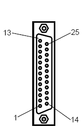
Connection Details
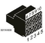
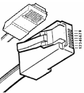
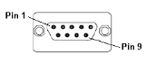
Illustrations below show the various end-of-cable connectors required:
| 25-Pin D-Type Male | 10-Pin Weidmuller
Cage Clamp |
8-Pin RJ 45 Plug | 9-Pin DB Male |
|
|
|
|
| CN1 | CN1 | MJ1/MJ2 | Port 1 |
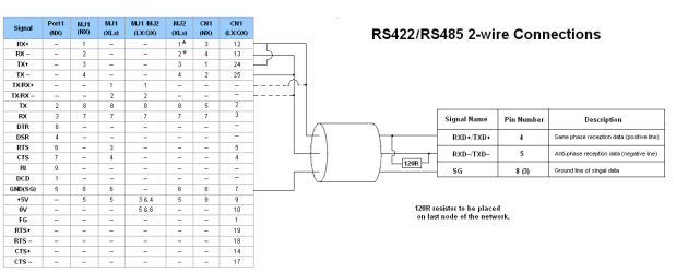
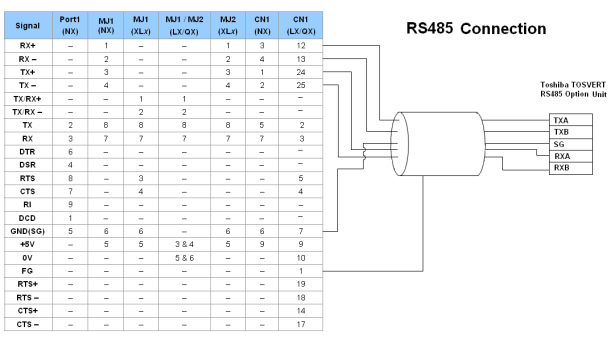
Following table indicates the Summary of the Serial port pin details for Serial communication. With this information RS-232/485/422 communication cables can be done.
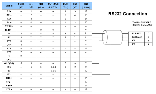
Port 1 — DB9 (Female at OCS end)
MJ1/MJ2 — RJ45 (Female at OCS end)
CN1 — 10-Pin Weidmuller Cage Clamp (Female at OCS end)
CN1 — DB25 (Female at OCS end)
NOTES:
-
Do not connect to unlisted pins.
-
Recommended Cable: Beldon 9503, twisted multipair, screened.
-
Connect the screens together at the shield / earth pin of the PLC.