Toshiba Computer Link Protocol
See also: Help for Serial Protocols
Overview
The Toshiba serial downloadable protocol is for communication between the Toshiba drives and an OCS. This is a Master/Slave protocol.
CSCAPE Configuration
To configure OCS for the Toshiba Computer Link protocol, select the Protocol Configuration from the Program menu in CSCAPE software. Select the appropriate protocol type on the desired port. To make sure that the Software is able to configure the equipment for the correct protocol, ensure ToshibaComputerLink.dll file is in the Protocols directory of the current working/open Cscape.
Protocol Revisions
Toshiba Computer Link Protocol supports master communications to the slave using ASCII commands.
Serial Port Format
The default link settings are : 9600 baud, No Parity, Eight data bits, RS232 Communication and No handshaking.
Communications in 232 mode is via the 7 way male D-sub port located on the top of the motor and the selected port.
Station Node Address
The station node address for the drive is default to 0 unless changed via the SADDR or ADDR= commands. If there is more than 1 motor on the bus, access is different. Sending 0x80 (0 in decimal) prior to the command will send the selected command to all motors on the bus (default on power up of drive). To specifically address one motor, send the specific address of the required motor before sending the command.
Commands
Each motor parameter is accessed as a command as described in the following section. When these commands are being accessed in CSCAPE the name of each command may be directly used.
NOTE: Every command must be configured as a 32-bit memory location for accessibility reasons i.e. even if the command is 8-bit, 16-bit or 32-bit the register must be given 32-bit of memory space. So if %R1 contains one command, %R3 should be used not %R2 for the next command.
Parameter Specification
The register addressing ranges selectable from within the OCS configurator have been chosen to allow the widest values of a particular family. Always check with the manufacture’s data to ensure selected register addresses are available. A chart showing the register types and ranges is included in this documentation.
NOTE: Some of the registers are READ ONLY. Trying to write to read only registers could cause unpredictable results and should be avoided.
Word Type Register Accesses
|
Name |
Type |
Access |
|
XW |
External input registers |
Read |
|
YW |
External output registers |
Read |
|
RW |
Auxiliary relay registers |
Read & Write |
|
SW |
Special registers |
Read |
|
T |
Timer registers |
Read |
|
C |
Counter registers |
Read |
|
D |
Data registers |
Read & Write |
|
ZX |
Link Registers |
Read |
Bit Types Register Accesses
|
Name |
Type |
Access |
|
X |
External input devices |
Read |
|
Y |
External output devices |
Read |
|
R |
Auxiliary relay devices |
Read & Write |
|
S |
Special devices |
Read |
|
T |
Timer Devices |
Read |
|
C |
Counter Devices |
Read |
|
Z |
Link Bits |
Read |
Register Ranges
NOTE: The following data is for guidance purposes only and must be confirmed by manufacturers own data on the relevant products. R & S device types are limited by the protocol to 63E not 63F as stated in the PLC Documentation. The Address is entered in the “Identifier box” as a combination of decimal and hexadecimal numbers, e.g. 31F or 15A or 270. The last digit represents the bit number within the word.
Word Register Ranges
|
Type |
Dir, |
T1 |
T1S |
T2E |
|
XW |
R |
00-31 |
00-31 |
00-63 |
|
YW |
R |
02-31 |
02-31 |
00-63 |
|
RW |
R/W |
00-63 |
00-255 |
00-255 |
|
SW |
R |
00-63 |
00-63 |
00-255 |
|
T |
R |
00-63 |
00-63 |
00-255 |
|
C |
R |
00-63 |
00-63 |
00-255 |
|
D |
R/W |
0-1023 |
0-4095 |
0-4095 |
|
ZX |
R |
0-31 |
0-31 |
0-63 |
Bit Register Ranges
|
Type |
Dir, |
T1 |
T1S |
T2E |
|
X |
R |
00-31F |
00-31F |
00-63F |
|
Y |
R |
00-31F |
00-31F |
00-63F |
|
R |
R/W |
FF-63E |
00-63E |
000-127F |
|
S |
R |
00-63E |
00-63E |
000-255F |
|
T |
R |
00-63 |
00-63 |
000-255 |
|
C |
R |
00-63 |
00-63 |
000-255 |
|
Z |
R |
00-31F |
00-31F |
00-31F |
Network Communication Errors
In order to access the Network statistics, user must assign the “Network status register” in network configuration. The table below gives the details of statistics.
| Number | Statistics | Location | Description |
|---|---|---|---|
|
|
|
|
|
|
1 |
Update interval exceeded count |
%Rx |
This register explains number of times that the actual transaction scan time to complete all transactions exceeded specified update interval. Generally used as an indicator that an excessive number of triggered transfers or failed communication retries are occurring that is lengthening the expected transaction scan time.
If the Update interval is set to zero (update as fast as possible), this 32-bit register alternately specifies the actual transaction scan time in mSec resolution. |
|
2 |
No response count |
%R(x+2) |
This register explains number of times that a device(s) did not respond to a transaction. This includes ALL failed transaction, not just those after the retry count is exceeded. |
|
3 |
Corrupt Response Count |
%R(x+4) |
This register explains number of times that a device(s) returned an invalid or failed response to a transaction. This includes ALL failed.
Transaction, not just those after the retry count is exceeded. |
|
4 |
Valid Response Count |
%R(x+6) |
This register explains total number of valid responses. |
NOTE: %Rx: 32-bit network status register configured in Network configuration. For example: %R500(501).
Device Communication Errors
| Error | Error Number | Description |
|---|---|---|
|
INVALID_BLOCK |
-203 |
Invalid size for data type. |
|
NO_RESPONSE_FROM_PLC |
-204 |
Timeout while waiting for remote node response. |
|
INVALID_RESPONSE_FROM_PLC |
-205 |
Corrupted response from remote node. |
|
INVALID_INITIALISATION |
-207 |
Internal Error - Unable to open port. |
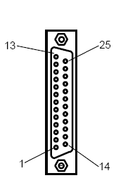
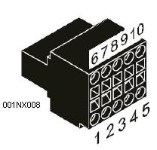
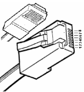
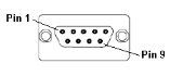
Connection Details
Illustrations below show the various end-of-cable connectors required:
| 25-Pin D-Type Male | 10-Pin Weidmuller
Cage Clamp |
8-Pin RJ 45 Plug | 9-Pin DB Male |
|
|
|
|
| CN1 | CN1 | MJ1/MJ2 | Port 1 |
Connection details to Toshiba T Series PLC’s/ Toshiba T2 Series PLC’s/ Toshiba T2N PLC’s (RS232)
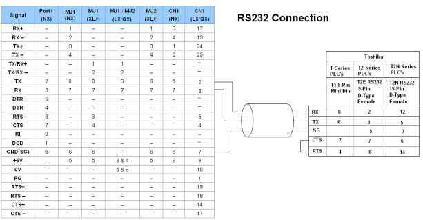
Port 1 — DB9 (Female at OCS end)
MJ1/MJ2 — RJ45 (Female at OCS end)
CN1 — 10-Pin Weidmuller Cage Clamp (Female at OCS end)
CN1 — DB25 (Female at OCS end)
NOTES:
-
Do not connect to unlisted pins.
-
Recommended Cable: Beldon 9503, twisted multipair, screened.
-
Connect the screens together at the shield / earth pin of the PLC.
Connection details to Toshiba EX, T2E, T1XS PLC’s / Toshiba T2N PLC’s (RS485)
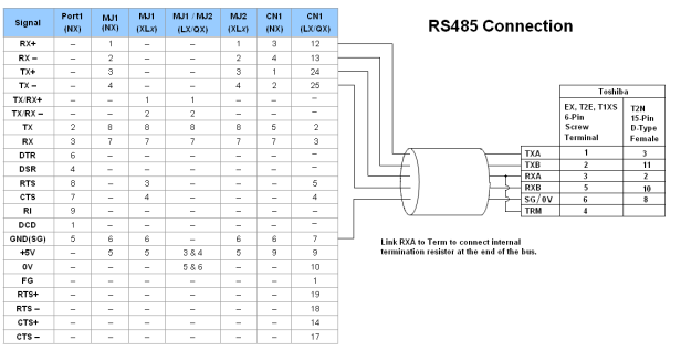
Port 1 — DB9 (Female at OCS end)
MJ1/MJ2 — RJ45 (Female at OCS end)
CN1 — 10-Pin Weidmuller Cage Clamp (Female at OCS end)
CN1 — DB25 (Female at OCS end)
NOTES:
-
Do not connect to unlisted pins.
-
Recommended Cable: Beldon 9503, twisted multipair, screened.
-
Connect the screens together at the shield / earth pin of the PLC.