Modbus Serial Protocol
See also: Help for Serial Protocols
MODBUS Serial is a variant of the MODBUS family of simple, vendor-neutral communication protocols. It is intended for supervision and control of automation equipment.
CSCAPE Configuration
To configure OCS for the MODBUS SERIAL protocol, select the Protocol Configuration from the Program menu in Cscape software. Select the appropriate protocol type in desired port. To make sure that the Software is able to configure the equipment for the correct protocol, ensure the Modbus.dll file is in the Protocols directory of the current working/open Cscape.
Serial Port Configuration
The default link settings for the terminal are : 9600 baud, No parity, Eight data bits, One stop bit, RS232 communication and No handshaking.
Modbus Addresses mapping for OCS
Modbus.dll (Version 1.11 and Later) supports the following addressing modes:
Generic Decimal Addressing
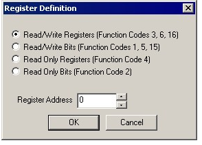
Use this when the connected device uses an addressing mode which does not correspond to a Modicon PLC, and offsets in the documentation for the target device are given in decimal. Addresses are entered in the following form:
<Data Type> <Decimal number>
Data type takes one of the following values
RWR : (Read Write Registers) Uses Modbus function codes 3, 6, 16
RWB : (Read Write Bits) Uses Modbus function codes 1, 5, 15
ROR : (Read Only Registers) Uses Modbus function code 4
ROB : (Read Only Bits) Uses Modbus function code 2
The decimal number gives the offset of the target data in the selected data type.
Generic Hexadecimal Addressing
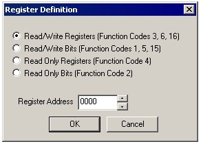
Use this when the connected device uses an addressing mode which does not correspond to a Modicon PLC, and offsets in the documentation for the target device are given in hexadecimal. Addresses are entered in the following form:
<Data Type> <Hexadecimal number>
Data type takes one of the following values
RWR : (Read Write Registers) Uses Modbus function codes 3, 6, 16
RWB : (Read Write Bits) Uses Modbus function codes 1, 5, 15
ROR : (Read Only Registers) Uses Modbus function code 4
ROB : (Read Only Bits) Uses Modbus function code 2
The hexadecimal number gives the offset of the target data in the selected data type.
Native OCS Addressing
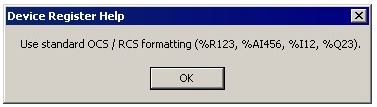
Use this when the connected device is an OCS unit running Modbus Slave.
Addresses are entered as standard OCS addresses, e.g. %R123, %M78
Modicon PLC 5 Digit Addressing
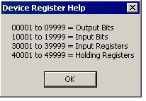
Use this when the connected device uses an addressing mode which corresponds to a reduced memory map Modicon PLC.
Address ranges supported are
00001-09999 - Read/Write Bits
10001-19999 - Read Only Bits
30001-39999 - Read only Registers
40001-49999 - Read Write Registers
Modicon PLC 6 Digit Addressing
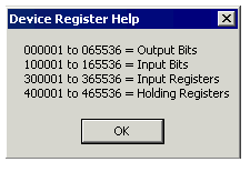
Use this when the connected device uses an addressing mode which corresponds to an extended memory map Modicon PLC.
Address ranges supported are
000001-065536 - Read/Write Bits
100001-165536 - Read Only Bits
300001-365536 - Read only Registers
400001-465536 - Read Write Registers
Configuring Modbus Master Device
Following are the steps for configuring Modbus master with Cscape application.
Step 1: Open Program -> Protocol Config and perform the following configurations:
Step 2: Select Modbus Master protocol from the drop-down list.
Step 3: On network configuration dialog user can configure following network parameters/status registers.
-
Configure Baud Rate, Parity, Stop Bits, Handshake, RTU/ANSI, RS-232/485, Retries, Timeout and Slave Speed.
-
Configure the update Scan type as automatic or manual according to process requirements.
-
Configure the (optional) network status register.
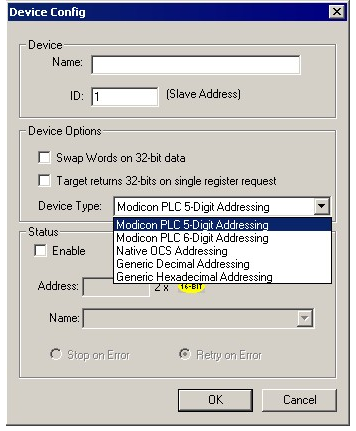
Step 4: Click Devices button to configure Slave device (0-247) as follows:
-
Configure slave device name and ID.
-
Select the addressing mode required when talking to this device.
-
If option for Swap Words on 32-bit Data is checked, the high and low 16-bit values of 32-bit Data are swapped when transferred between the target and OCS.
-
Device status registers can be optionally enabled and used to determine the current state of communications.
-
Select Stop on Error or Retry on Error as per process requirement.
Step 5: Click Scan List button to configure Data Mapping.
-
To transfer data between the OCS and remote target, a Scan List must be created that defines each transaction. Each mapping entry (transaction) contains the source and destination registers, the number of consecutive registers transferred, the direction of the transfer and trigger for transfer (optional). Maximum number of entries is 512. NOTE: Order of the Scan List is the order in which the transactions occur.
-
Scan list for a master device is developed in the following steps: Click Add button to Invoke the Data Mapping dialog for adding new entry to the Scan List.
Configure:
-
Device Name: Select the target device from the drop-down list. Only those device entries previously created from the Device Config menu are available.
-
Device Register: Specify the target device’s register to be mapped according to the selected addressing mode.
-
32-Bit Access: Allows two local (OCS) 16-bit registers to be treated as a single 32-bit value. For example, if the value in either 16-bit register is modified, both registers are written to the device. (only command 3 & 16 are used).
-
Length: Specify the number of consecutive device registers to Read / Write. Maximum length is 32.
-
Local Register: Specify the local (OCS) register that is the source or destination for transfer of the data.
-
Local Name (Optional): Enter / select name for the Local Register.
-
Update Type: This field specifies the direction and triggers the transfer of data between the OCS and target device. Select Update Type as per the system requirements.
-
Floating Point Access
Some venders return 32-bit IEEE floating point values in response to a Read Modbus Analog Input or Holding register (reads made to the 30001-49999 address range). This driver accepts and loads two consecutive OCS registers with this 32-bit value if the associated Device Config menu for this device has the Target returns 32-bits on single register request option selected. Should the word order of the incoming data be reversed, the Device Config menu option Swap words on 32-bit data may be used to correct the data orientation.
Virtual 32-bit transfers
When 32-bit access is selected from the Data Mapping menu for a specific transaction, any local change to either of the two local OCS registers associated with a virtual 32-bit point causes both register values to be written to the remote device in the same transaction (assumes either Read/Write or Read/Write/Init type configuration)
Network Communication Errors
In order to access the Network statistics, user must assign the “Network status register” in network configuration. The table below gives the details of statistics.
| Number | Statistics | Location | Description |
|---|---|---|---|
|
|
|
|
|
|
1 |
Update interval exceeded count |
%Rx |
This register explains number of times that the actual transaction scan time to complete all transactions exceeded specified update interval. Generally used as an indicator that an excessive number of triggered transfers or failed communication retries are occurring that is lengthening the expected transaction scan time.
If the Update interval is set to zero (update as fast as possible), this 32-bit register alternately specifies the actual transaction scan time in mSec resolution. |
|
2 |
No response count |
%R(x+2) |
This register explains number of times that a device(s) did not respond to a transaction. This includes ALL failed transaction, not just those after the retry count is exceeded. |
|
3 |
Corrupt Response Count |
%R(x+4) |
This register explains number of times that a device(s) returned an invalid or failed response to a transaction. This includes ALL failed.
Transaction, not just those after the retry count is exceeded. |
|
4 |
Valid Response Count |
%R(x+6) |
This register explains total number of valid responses. |
NOTE: %Rx: 32-bit network status register configured in Network configuration. For example: %R500(501).
Device Communication Errors
|
Error |
Error Number |
|
master does not support |
0x00C5 (197) |
|
master invalid plc ref |
0x00C6 (198) |
|
exceed mode frame |
0x00C8 (200) |
|
time out |
0x0081 (129) |
|
cRC error |
0x0082 (130) |
|
response bad Format |
0x0083 (131) |
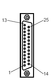
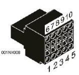
Connection Details
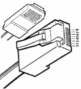
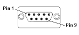
Illustrations below show the various end-of-cable connectors required:
| 25-Pin D-Type Male | 10-Pin Weidmuller
Cage Clamp |
8-Pin RJ 45 Plug | 9-Pin DB Male |
|
|
|
|
| CN1 | CN1 | MJ1/MJ2 | Port 1 |
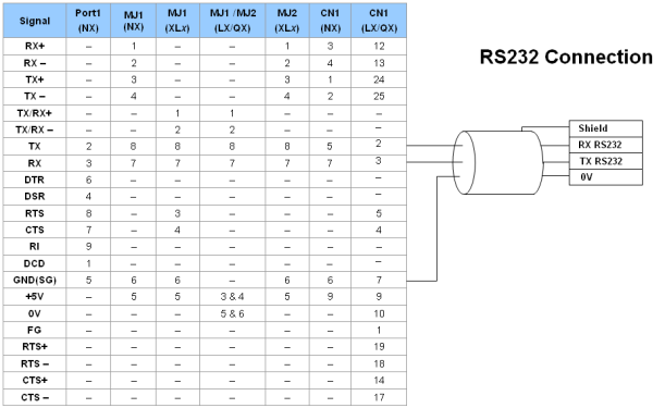
Port 1 — DB9 (Female at OCS end)
MJ1/MJ2 — RJ45 (Female at OCS end)
CN1 — 10-Pin Weidmuller Cage Clamp (Female at OCS end)
CN1 — DB25 (Female at OCS end)
NOTES:
-
Do not connect to unlisted pins.
-
Recommended Cable: Beldon 9503, twisted multipair, screened.
-
Connect the screens together at the shield / earth pin of the PLC.
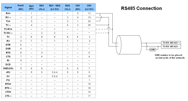
RS485 Full Duplex/RS422
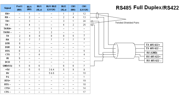
Port 1 — DB9 (Female at OCS end)
MJ1/MJ2 — RJ45 (Female at OCS end)
CN1 — 10-Pin Weidmuller Cage Clamp (Female at OCS end)
CN1 — DB25 (Female at OCS end)
NOTES:
-
Do not connect to unlisted pins.
-
Recommended Cable: Beldon 9503, twisted multipair, screened.
-
Connect the screens together at the shield / earth pin of the PLC.
Opening an existing project created using Modbus DLL Version 1.05 requires modification of scan list as it is not compatible with present version of Modbus DLL. However in Cscape version 8.6 and onwards if application written using Modbus DLL Version 1.05 is opened, it will displays the following message:
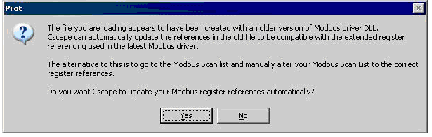
On selecting Yes, it will automatically updates the scan list parameters make it compatible with present version of Modbus DLL. If selected No, scan list parameters need to be modified manually.
After updating, it will not be backward compatible with Modbus DLL Version 1.05.