KEB Protocol
See also: Help for Serial Protocols
Overview
The KEB DIN66019 II (ANSI X3.28 / ISO 1745 compatible) serial downloadable protocol is for communication between the KEB inverters and an OCS. This is a Master/Slave protocol.
KEB protocol supports master only operation to the slave Inverter using the KEB protocol. Communication is via the 9 pin ‘D’ type Female connector located on the front of the inverter.
CSCAPE Configuration
To configure OCS for the KEB protocol, select the Protocol Configuration from the Program menu in CSCAPE software. Select the appropriate protocol type on the desired port. To make sure that the Software is able to configure the equipment for the correct protocol, ensure keb.dll file is in the Protocols directory of the current working/open Cscape.
Serial Port Configuration
The default communications settings are : 9600 baud, Even parity, Seven data bits, One stop bit and No handshaking. For communications, the connector may be wired as RS232 or RS485.
Node Number
Global Remote Node ID default address is 1.
The address of drive may be changed in parameter ud 6 within the range 1 to 239. This may be changed from the OCS, once changed, communication will no longer be possible until the Communication node address has been changed in the configuration to be the same as the Drive.
Broadcasting to multiple drives simultaneously
Broadcasting to a multiple of networked drives is possible with this Drive. The Comms mode must be set to RS422/485 with the Network Mode Enable.
Address 240 in the OCS will broadcast to KEB COMBIVERT addresses 0-15 and will read from address 0.
Address 241 in the OCS will broadcast to KEB COMBIVERT addresses 16-31 and will read from address 16.
.
.
.
Address 254 in the OCS will broadcast to KEB COMBIVERT addresses 224-239 and will read from address 224.
NOTE: On a broadcast network, reads can only be from the lowest address in the group. Attempting to read from any
other address will result in a communication failure and will show as *****.
NOTE: If Parameter address used which is not specified in the list will generate undetermined result.
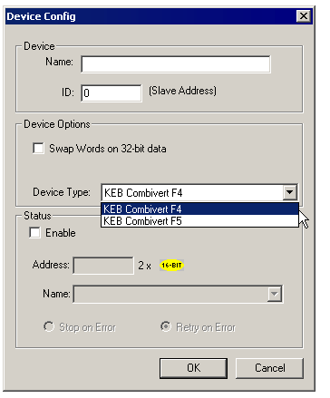
Selecting Device Type
Select the desired device type 'Combivert F4' or 'Combivert F5' from Device Type list.
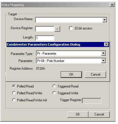
Enter the desired parameter address in the Device Register field or use button to select the desired parameter from the drop-down list. There are two drop-down lists viz. Parameter Type and Parameter.
There are two ways of accessing parameters:
-
By selecting Parameter type and Parameter from the drop-down list. The following diagram shows selecting Pr-04 (Pole –Number) from the drop-down list.
-
By entering the hex address directly in the Device Register field. E.g. to select Pr-04 parameter, type 012Ah in the Device register field. Using this, the parameters which are not present in the drop-down list can also be accessed.
Combiverter F4 parameters
Link to Combiverter F5 parameters
|
No. |
Parameter Name |
Address on F4 |
|
1 |
Pr-04 : Pole Number |
012Ah |
|
2 |
Pr-05 : Malfunction Code |
0105h |
|
3 |
Pr-06 : Control Word |
0106h |
|
4 |
Pr-07 : Status Word |
0107h |
|
5 |
Pr-08 : Nominal Speed Value |
0108h |
|
6 |
Pr-09 : Actual Speed Value |
0109h |
|
7 |
Pr-10 : Speed Min. Amount |
010Ah |
|
8 |
Pr-11 : Speed Max. Amount |
010Bh |
|
9 |
Pr-16 : Acceleration Delta Speed |
0110h |
|
10 |
Pr-18 : Acceleration Delta Time |
0112h |
|
11 |
Pr-25 : Deceleration Delta Speed |
0119h |
|
12 |
Pr-27 : Deceleration Delta Time |
011Bh |
|
13 |
Pr-37 : Speed Control Variable |
0125h |
|
14 |
Pr-38 : Set Value Percentage |
0126h |
|
15 |
Pr-39 : Percentage Reference Value |
0127h |
|
16 |
Pr-40 : Actual Percentage |
0128h |
|
17 |
Pr-41 : Percentage Control Variable |
0129h |
|
18 |
ru-00 : Inverter State |
2000h |
|
19 |
ru-01 : Actual Speed Display |
2001h |
|
20 |
ru-03 : Actual Frequency Display |
2003h |
|
21 |
ru-04 : Set Speed Display |
2004h |
|
22 |
ru-06 : Set Frequency Display |
2006h |
|
23 |
ru-07 : Actual Inverter Utilization |
2007h |
|
24 |
ru-08 : Peak Inverter Utilization |
2008h |
|
25 |
ru-09 : Apparent Current |
2009h |
|
26 |
ru-10 : Active Current |
200Ah |
|
27 |
ru-11 : Actual DC Voltage |
200Bh |
|
28 |
ru-12 : Peak DC Voltage |
200Ch |
|
29 |
ru-13 : Output Voltage |
200Dh |
|
30 |
ru-14 : Input Terminal State |
200Eh |
|
31 |
ru-15 : Output Terminal State |
200Fh |
|
32 |
ru-16 : Internal Input State |
2010h |
|
33 |
ru-17 : Internal Output State |
2011h |
|
34 |
ru-18 : Actual Parameterset |
2012h |
|
35 |
ru-22 : Ref 1 display |
2016h |
|
36 |
ru-23 : Ref 2 display |
2017h |
|
37 |
ru-24 : OL Counter Display |
2018h |
|
38 |
ru-29 : Heat Sink Temperature |
201Dh |
|
39 |
ru-30 : Ext. PI Output Display |
201Eh |
|
40 |
ru-31 : Power On Counter |
201Fh |
|
41 |
ru-32 : Modulation On Counter |
2020h |
|
42 |
ru-33 : Timer A Act. Value |
2021h |
|
43 |
ru-34 : Motorpoti Act. Value |
2022h |
|
44 |
ru-41 : Analog Out 1 Display |
2029h |
|
45 |
ru-43 : Programmable Display |
202Bh |
|
46 |
ru-44 : Act. Switching Freq. |
202Ch |
|
47 |
ru-45 : Aanalog Option Display |
202Dh |
|
48 |
ru-46 : Ramp Frequency |
202Eh |
|
49 |
ru-47 : Act Encoder Frequency |
202Fh |
|
50 |
oP-00 : Reference Source |
2100h |
|
51 |
oP-01 : Freq. Reference Setting Abs. |
2101h |
|
52 |
oP-02 : Freq. Reference Setting % |
2102h |
|
53 |
oP-03 : Rotation Setting |
2103h |
|
54 |
oP-04 : Min. Freq. Reference Forward |
2104h |
|
55 |
oP-05 : Max. Freq. Reference Forward |
2105h |
|
56 |
oP-06 : Min. Freq. Reference Reverse |
2106h |
|
57 |
oP-07 : Max. Freq. Reference Reverse |
2107h |
|
58 |
oP-08 : Abs. Max. Freq. Forward |
2108h |
|
59 |
oP-09 : Abs. Max. Freq. Reverse |
2109h |
|
60 |
oP-10 : Acc Dec Mode |
210Ah |
|
61 |
oP-11 : Acceleration Time Forward |
210Bh |
|
62 |
oP-12 : Deceleration Time Forward |
210Ch |
|
63 |
oP-13 : Acceleration Time Reverse |
210Dh |
|
64 |
oP-14 : Deceleration Time Reverse |
210Eh |
|
65 |
oP-15 : S-Curve Time Acc. Forward |
210Fh |
|
66 |
oP-16 : S-Curve Time Dec. Forward |
2110h |
|
67 |
oP-17 : S-Curve Time Acc. Reverse |
2111h |
|
68 |
oP-18 : S-Curve Time Dec. Reverse |
2112h |
|
69 |
oP-22 : Step Frequency 1 |
2116h |
|
70 |
oP-23 : Step Frequency 2 |
2117h |
|
71 |
oP-24 : Step Frequency 3 |
2118h |
|
72 |
oP-25 : Step Frequency Mode |
2119h |
|
73 |
oP-26 : Motorpoti Function |
211Ah |
|
74 |
oP-27 : Motorpoti Min. Value |
211Bh |
|
75 |
oP-28 : Motorpoti Max. Value |
211Ch |
|
76 |
oP-29 : Motorpoti Inc./Dec. Time 211 |
211Dh |
|
77 |
oP-30 : Motorpoti Prescaler 211E |
211Eh |
|
78 |
oP-31 : Motorpoti Destination 211F |
211Fh |
|
79 |
oP-32 : Max. Output Freq. Forward 21 |
2120h |
|
80 |
oP-33 : Max. Output Freq. Reverse 21 |
2121h |
|
81 |
Pn-00 : Auto Restart UP |
2200h |
|
82 |
Pn-01 : Auto Restart UP |
2201h |
|
83 |
Pn-02 : Auto Restart OC |
2202h |
|
84 |
Pn-03 : Motorprotection / Mode |
2203h |
|
85 |
Pn-04 : LAD Stop Function |
2204h |
|
86 |
Pn-05 : LAD Load Level |
2205h |
|
87 |
Pn-06 : LD Voltage |
2206h |
|
88 |
Pn-07 : Speed Search Condition |
2207h |
|
89 |
Pn-08 : DC Braking Mode |
2208h |
|
90 |
Pn-09 : DC Braking Start Freq. |
2209h |
|
91 |
Pn-10 : DC Braking Max. Voltage |
220Ah |
|
92 |
Pn-11 : DC Braking Time |
220Bh |
|
93 |
Pn-12 : Stall Mode |
220Ch |
|
94 |
Pn-13 : Stall Level |
220Dh |
|
95 |
Pn-14 : Stall Acc/Dec Time |
220Eh |
|
96 |
Pn-15 : Motorprotection / Counter Selection |
220Fh |
|
97 |
Pn-16 : E.dOH Delay Time |
2210h |
|
98 |
Pn-17 : Power Off Starting Voltage |
2211h |
|
99 |
Pn-18 : Power Off Braking Torque |
2212h |
|
100 |
Pn-19 : Power Off Restart Frequency |
2213h |
|
101 |
Pn-33 : Power Off Mode |
2221h |
|
102 |
Pn-34 : Power Off KP Uzk |
2222h |
|
103 |
Pn-36 : Power Off KP Iw |
2224h |
|
104 |
Pn-37 : Power Off KI Iw |
2225h |
|
105 |
Pn-38 : Power Off Jump Factor |
2226h |
|
106 |
Pn-42 : Power Off Set Voltage |
222Ah |
|
107 |
Pn-43 : Power Off Wait Time |
222Bh |
|
108 |
Pn-50 : Speed Search Mode |
2232h |
|
109 |
Pn-51 : Brake Mode |
2233h |
|
110 |
Pn-52 : Start Time 1 |
2234h |
|
111 |
Pn-53 : Start Time 2 |
2235h |
|
112 |
Pn-54 : Start Frequency |
2236h |
|
113 |
Pn-55 : Stop Time 1 |
2237h |
|
114 |
Pn-56 : Stop Time 2 |
2238h |
|
115 |
Pn-57 : Stop Frequency |
2239h |
|
116 |
Pn-58 : Min. Load for Brake Control |
223Ah |
|
117 |
Pn-61 : Auto Restart E.net |
223Dh |
|
118 |
uF-00 : Rated Frequency |
2300h |
|
119 |
uF-01 : Boost |
2301h |
|
120 |
uF-02 : Additional Rated Freq. |
2302h |
|
121 |
uF-03 : Additional Rated Voltage |
2303h |
|
122 |
uF-04 : Delta Boost |
2304h |
|
123 |
uF-05 : Delta Boost Time |
2305h |
|
124 |
uF-06 : Energy Saving Mode |
2306h |
|
125 |
uF-07 : Energy Saving Level |
2307h |
|
126 |
uF-08 : DC Voltage Compensation |
2308h |
|
127 |
uF-09 : Min. Freq. For Modulation |
2309h |
|
128 |
uF-10 : Modulation Mode |
230Ah |
|
129 |
uF-11 : Carrier Frequency |
230Bh |
|
130 |
uF-16 : Current Limitation ON/OFF |
2310h |
|
131 |
uF-17 : Transistor on Delay Time Comp. ON/OFF |
2311h |
|
132 |
dr-01 : Rated Motor Speed |
2401h |
|
133 |
dr-02 : Rated Motor Current |
2402h |
|
134 |
dr-03 : Rated Motor Frequency |
2403h |
|
135 |
dr-04 : Rated Motor cos(Phi) |
2404h |
|
136 |
dr-05 : Motor Terminal Resistance |
2405h |
|
137 |
dr-12 : Rated motor voltage |
240Ch |
|
138 |
dr-22 : Breakdown Factor |
2416h |
|
139 |
dr-24 : Interface Select |
2418h |
|
140 |
dr-25 : Encoder 1 (inc/r) |
2419h |
|
141 |
dr-29 : Change Encoder 1 Rotation |
241Dh |
|
142 |
dr-30 : Encoder 2 (inc/r) |
241Eh |
|
143 |
dr-34 : Change Encoder 2 Rotation |
2422h |
|
144 |
dr-35 : Gear Ratio Channel 1 |
2423h |
|
145 |
dr-36 : Gear Ratio Channel 2 |
2424h |
|
146 |
dr-37 : Filter Encoder 1 |
2425h |
|
147 |
dr-38 : Filter Encoder 2 |
2426h |
|
148 |
dr-43 : Initiator Direction |
242Bh |
|
149 |
dr-44 : Reference Speed Tacho Evaluation |
242Ch |
|
150 |
cn-00 : Control Mode |
2500h |
|
151 |
cn-01 : Slip Compensation Gain |
2501h |
|
152 |
cn-02 : Torque Compensation Gain |
2502h |
|
153 |
cn-03 : Act. Speed Source |
2503h |
|
154 |
cn-10 : Ext. PI Add Ref Fmin |
250Ah |
|
155 |
cn-11 : Ext. PI Add Ref Fmax |
250Bh |
|
156 |
cn-12 : Ext. PI Add Ref Source |
250Ch |
|
157 |
cn-13 : Ext. PI Add Ref Function |
250Dh |
|
158 |
cn-14 : Ext. PI Delta Ref Max. |
250Eh |
|
159 |
cn-15 : Ext. PI Ref Absolut |
250Fh |
|
160 |
cn-16 : Ext. PI KP |
2510h |
|
161 |
cn-17 : Ext. PI KI |
2511h |
|
162 |
cn-18 : Ext. PI Pos. Max. |
2512h |
|
163 |
cn-19 : Ext. PI Neg. Min. |
2513h |
|
164 |
cn-20 : Ext. PI act. Value Source |
2514h |
|
165 |
cn-21 : Ext. PI Reset Condition |
2515h |
|
166 |
cn-22 : Ext. PI Act. Value Absolut |
2516h |
|
167 |
cn-25 : Ext. PI Frequency Ratio |
2519h |
|
168 |
cn-26 : Ext. PI Fade In Time |
251Ah |
|
169 |
cn-27 : Ext. PI Frequency Limit |
251Bh |
|
170 |
cn-30 : Diameter Compensation Source |
251Eh |
|
171 |
cn-31 : Digital Diameter Input |
251Fh |
|
172 |
cn-32 : Diameter Ratio |
2520h |
|
173 |
cn-33 : Diameter Inc/Dec Time |
2521h |
|
174 |
ud-00 : Key Password Input |
2600h |
|
175 |
ud-01 : Bus Password Input |
2601h |
|
176 |
ud-02 : Start Parameter Group |
2602h |
|
177 |
ud-03 : Start Parameter Number |
2603h |
|
178 |
ud-05 : Controlword Activation |
2605h |
|
179 |
ud-06 : Inverter Address |
2606h |
|
180 |
ud-07 : Baud Rate |
2607h |
|
181 |
ud-08 : Watchdog Time |
2608h |
|
182 |
ud-09 : Drive Mode Control |
2609h |
|
183 |
ud-10 : Display Mode |
260Ah |
|
184 |
ud-11 : Maximum Frequency Mode |
260Bh |
|
185 |
ud-13 : cP0 Address |
260Dh |
|
186 |
ud-14 : cP0 Set |
260Eh |
|
187 |
ud-15 : cP1 Address |
260Fh |
|
188 |
ud-16 : cP1 Set |
2610h |
|
189 |
ud-17 : cP2 Address |
2611h |
|
190 |
ud-18 : cP2 Set |
2612h |
|
191 |
ud-19 : cP3 Address |
2613h |
|
192 |
ud-20 : cP3 Set |
2614h |
|
193 |
ud-21 : cP4 Address |
2615h |
|
194 |
ud-22 : cP4 Set |
2616h |
|
195 |
ud-23 : cP5 Address |
2617h |
|
196 |
ud-24 : cP5 Set |
2618h |
|
197 |
ud-25 : cP6 Address |
2619h |
|
198 |
ud-26 : cP6 Set |
261Ah |
|
199 |
ud-27 : cP7 Address |
261Bh |
|
200 |
ud-28 : cP7 Set |
261Ch |
|
201 |
ud-29 : cP8 Address |
261Dh |
|
202 |
ud-30 : cP8 Set |
261Eh |
|
203 |
ud-31 : cP9 Address |
261Fh |
|
204 |
ud-32 : cP9 Set |
2620h |
|
205 |
ud-33 : cP10 Address |
2621h |
|
206 |
ud-34 : cP10 Set |
2622h |
|
207 |
ud-35 : cP11 Address |
2623h |
|
208 |
ud-36 : cP11 Set |
2624h |
|
209 |
ud-37 : cP12 Address |
2625h |
|
210 |
ud-38 : cP12 Set |
2626h |
|
211 |
ud-39 : cP13 Address |
2627h |
|
212 |
ud-40 : cP13 Set |
2628h |
|
213 |
ud-41 : cP14 Address |
2629h |
|
214 |
ud-42 : cP14 Set |
262Ah |
|
215 |
ud-43 : cP15 Address |
262Bh |
|
216 |
ud-44 : cP15 Set |
262Ch |
|
217 |
ud-45 : cP16 Address |
262Dh |
|
218 |
ud-46 : cP16 Set |
262Eh |
|
219 |
ud-47 : cP17 Address |
262Fh |
|
220 |
ud-48 : cP17 Set |
2630h |
|
221 |
ud-49 : cP18 Address |
2631h |
|
222 |
ud-50 : cP18 Set |
2632h |
|
223 |
ud-51 : cP19 Address |
2633h |
|
224 |
ud-52 : cP19 Set |
2634h |
|
225 |
ud-53 : cP20 Address |
2635h |
|
226 |
ud-54 : cP20 Set |
2636h |
|
227 |
ud-55 : cP21 Address |
2637h |
|
228 |
ud-56 : cP21 Set |
2638h |
|
229 |
ud-57 : cP22 Address |
2639h |
|
230 |
ud-58 : cP22 Set |
263Ah |
|
231 |
ud-59 : cP23 Address |
263Bh |
|
232 |
ud-60 : cP23 Set |
263Ch |
|
233 |
ud-61 : cP24 Address |
263Dh |
|
234 |
ud-62 : cP24 Set |
263Eh |
|
235 |
ud-87 : Display Scaling Source |
2657h |
|
236 |
ud-88 : Display Scaling Multiplier |
2658h |
|
237 |
ud-89 : Display Scaling Divisor |
2659h |
|
238 |
ud-90 : Display Scaling Offset |
265Ah |
|
239 |
ud-91 : Display Scaling Post Dec. Pos |
265Bh |
|
240 |
Fr-00 : Copy Para Set (Key) |
2700h |
|
241 |
Fr-01 : Copy Para Set (Bus) |
2701h |
|
242 |
Fr-02 : Parameter Set Source |
2702h |
|
243 |
Fr-03 : Parameter Set Lock |
2703h |
|
244 |
Fr-04 : Parameter Set Setting |
2704h |
|
245 |
Fr-05 : Parameter Set Activation Delay |
2705h |
|
246 |
Fr-06 : Parameter Set Deactivation Delay |
2706h |
|
247 |
Fr-09 : Bus Parameter Set |
2709h |
|
248 |
An-01 : Noise Filter Ref 1 |
2801h |
|
249 |
An-02 : Zero Clamp Ref 1 |
2802h |
|
250 |
An-03 : Ref 1 Gain |
2803h |
|
251 |
An-04 : Ref 1 Offset X |
2804h |
|
252 |
An-05 : Ref 1 Offset Y |
2805h |
|
253 |
An-06 : Ref 2 - Interface - Definition |
2806h |
|
254 |
An-07 : Noise Filter Ref 2 |
2807h |
|
255 |
An-08 : Zero Clamp Ref 2 |
2808h |
|
256 |
An-09 : Ref 2 Gain |
2809h |
|
257 |
An-10 : Ref 2 Offset X |
280Ah |
|
258 |
An-11 : Ref 2 Offset Y |
280Bh |
|
259 |
An-12 : Reference/Aux Selection |
280Ch |
|
260 |
An-13 : Aux Function |
280Dh |
|
261 |
An-14 : Analog Out1 Function |
280Eh |
|
262 |
An-15 : Analog Out1 Gain |
280Fh |
|
263 |
An-16 : Analog Out1 Offset X |
2810h |
|
264 |
An-17 : Analog Out1 Offset Y |
2811h |
|
265 |
An-22 : Analog In Mode |
2816h |
|
266 |
An-23 : Analog Option Gain |
2817h |
|
267 |
An-24 : Analog Option Offset X |
2818h |
|
268 |
An-25 : Analog Option Offset Y |
2819h |
|
269 |
An-26 : Noise Filter Analog Option |
281Ah |
|
270 |
An-27 : Zero Clamp Analog Option |
281Bh |
|
271 |
di-00 : Noise Filter Digital |
2900h |
|
272 |
di-01 : NPN/PNP Selection |
2901h |
|
273 |
di-02 : Input Logic |
2902h |
|
274 |
di-03 : Input Function I1 |
2903h |
|
275 |
di-04 : Input Function I2 |
2904h |
|
276 |
di-05 : Input Function I3 |
2905h |
|
277 |
di-06 : Input Function I4 |
2906h |
|
278 |
di-07 : Input Function IA |
2907h |
|
279 |
di-08 : Input Function IB |
2908h |
|
280 |
di-09 : Input Function IC |
2909h |
|
281 |
di-10 : Input Function ID |
290Ah |
|
282 |
di-14 : Input Trigger |
290Eh |
|
283 |
di-15 : Select Signal Source |
290Fh |
|
284 |
di-16 : Digital Input Setting |
2910h |
|
285 |
di-17 : Input Strobe Dependance |
2911h |
|
286 |
di-18 : Select Strobe Source |
2912h |
|
287 |
di-19 : Select Strobe Mode |
2913h |
|
288 |
di-20 : Rotation Input |
2914h |
|
289 |
di-21 : Reset Mode for ST |
2915h |
|
290 |
do-00 : Output Logic |
2A00h |
|
291 |
do-01 : Output Condition 1 |
2A01h |
|
292 |
do-02 : Output Condition 2 |
2A02h |
|
293 |
do-03 : Output Condition 3 |
2A03h |
|
294 |
do-04 : Output Condition 4 |
2A04h |
|
295 |
do-09 : Select Out 1 Condition |
2A09h |
|
296 |
do-10 : Select Out 2 Condition |
2A0Ah |
|
297 |
do-11 : Select Out 3 Condition |
2A0Bh |
|
298 |
do-13 : Select Out A Condition |
2A0Dh |
|
299 |
do-14 : Select Out B Condition |
2A0Eh |
|
300 |
do-15 : Select Out C Condition |
2A0Fh |
|
301 |
do-16 : Select Out D Condition |
2A10h |
|
302 |
do-17 : Out 1 Condition Logic |
2A11h |
|
303 |
do-18 : Out 2 Condition Logic |
2A12h |
|
304 |
do-19 : Out 3 Condition Logic |
2A13h |
|
305 |
do-21 : Out A Condition Logic |
2A15h |
|
306 |
do-22 : Out B Condition Logic |
2A16h |
|
307 |
do-23 : Out C Condition Logic |
2A17h |
|
308 |
do-24 : Out D Condition Logic |
2A18h |
|
309 |
do-25 : Output Condition Connection |
2A19h |
|
310 |
LE-00 : Frequency Level 1 |
2B00h |
|
311 |
LE-01 : Frequency Level 2 |
2B01h |
|
312 |
LE-02 : Frequency Level 3 |
2B02h |
|
313 |
LE-03 : Frequency Level 4 |
2B03h |
|
314 |
LE-08 : Load Level 1 |
2B08h |
|
315 |
LE-09 : Load Level 2 |
2B09h |
|
316 |
LE-10 : Load Level 3 |
2B0Ah |
|
317 |
LE-11 : Load Level 4 |
2B0Bh |
|
318 |
LE-16 : Active Current Level 1 |
2B10h |
|
319 |
LE-17 : Active Current Level 2 |
2B11h |
|
320 |
LE-18 : Active Current Level 3 |
2B12h |
|
321 |
LE-19 : Active Current Level 4 |
2B13h |
|
322 |
LE-24 : DC Voltage Level 1 |
2B18h |
|
323 |
LE-25 : DC Voltage Level 2 |
2B19h |
|
324 |
LE-26 : DC Voltage Level 3 |
2B1Ah |
|
325 |
LE-27 : DC Voltage Level 4 |
2B1Bh |
|
326 |
LE-32 : OL Warning Level |
2B20h |
|
327 |
LE-34 : OH Warning Level |
2B22h |
|
328 |
LE-35 : Timer Value |
2B23h |
|
329 |
LE-36 : Frequency Hysteresis |
2B24h |
|
330 |
LE-41 : Timer A Level 1 |
2B29h |
|
331 |
LE-42 : Timer A Level 2 |
2B2Ah |
|
332 |
LE-43 : Timer A Level 3 |
2B2Bh |
|
333 |
LE-44 : Timer A Level 4 |
2B2Ch |
|
334 |
LE-45 : Timer A Reset Condition |
2B2Dh |
|
335 |
LE-46 : Timer A Inc Condition |
2B2Eh |
|
336 |
LE-47 : Timer A Resolution |
2B2Fh |
|
337 |
LE-62 : Percentage Level 1 |
2B3Eh |
|
338 |
LE-63 : Percentage Level 2 |
2B3Fh |
|
339 |
LE-64 : Percentage Level 3 |
2B40h |
|
340 |
LE-65 : Percentage Level 4 |
2B41h |
|
341 |
LE-69 : Analog Hysteresis |
2B45h |
|
342 |
In-00 : Inverter Type |
2C00h |
|
343 |
In-01 : Rated Inverter Current |
2C01h |
|
344 |
In-02 : Max. Output Frequency |
2C02h |
|
345 |
In-03 : Max. Carrier Frequency |
2C03h |
|
346 |
In-04 : Software Version |
2C04h |
|
347 |
In-05 : Software Date |
2C05h |
|
348 |
In-06 : Configfile No. |
2C06h |
|
349 |
In-07 : Serial No. (Date) |
2C07h |
|
350 |
In-08 : Serial No. (Counter) |
2C08h |
|
351 |
In-09 : Serial No. (AB-no. High) |
2C09h |
|
352 |
In-10 : Serial No. (AB-no. Low) |
2C0Ah |
|
353 |
In-11 : Cust. No. (High) |
2C0Bh |
|
354 |
In-12 : Cust. No. (Low) |
2C0Ch |
|
355 |
In-13 : QS No. |
2C0Dh |
|
356 |
In-15 : REF Offset + |
2C0Fh |
|
357 |
In-16 : REF Offset - |
2C10h |
|
358 |
In-17 : REF Gain + |
2C11h |
|
359 |
In-18 : REF Gain - |
2C12h |
|
360 |
In-19 : REF2 0-10V Offset |
2C13h |
|
361 |
In-20 : REF2 0-10V Gain |
2C14h |
|
362 |
In-21 : REF2 0-20mA Offset |
2C15h |
|
363 |
In-22 : REF2 0-20mA Gain |
2C16h |
|
364 |
In-23 : REF2 4-20mA Offset |
2C17h |
|
365 |
In-24 : REF2 4-20mA Gain |
2C18h |
|
366 |
In-40 : Last Error |
2C28h |
|
367 |
In-41 : Error Counter OC |
2C29h |
|
368 |
In-42 : Error Counter OL |
2C2Ah |
|
369 |
In-43 : Error Counter OP |
2C2Bh |
|
370 |
In-44 : Error Counter OH |
2C2Ch |
|
371 |
In-45 : Error Counter buS |
2C2Dh |
|
372 |
In-58 : User Parameter 1 |
2C3Ah |
|
373 |
In-59 : User Parameter 2 |
2C3Bh |
|
374 |
CP-00 : Password Key |
2600h |
|
375 |
CP-00 : Password Bus |
2601h |
|
376 |
CP-01 : User defined |
3301h |
|
377 |
CP-02 : User defined |
3302h |
|
378 |
CP-03 : User defined |
3303h |
|
379 |
CP-04 : User defined |
3304h |
|
380 |
CP-05 : User defined |
3305h |
|
381 |
CP-06 : User defined |
3306h |
|
382 |
CP-07 : User defined |
3307h |
|
383 |
CP-08 : User defined |
3308h |
|
384 |
CP-09 : User defined |
3309h |
|
385 |
CP-10 : User defined |
330Ah |
|
386 |
CP-11 : User defined |
330Bh |
|
387 |
CP-12 : User defined |
330Ch |
|
388 |
CP-13 : User defined |
330Dh |
|
389 |
CP-14 : User defined |
330Eh |
|
390 |
CP-15 : User defined |
330Fh |
|
391 |
CP-16 : User defined |
3310h |
|
392 |
CP-17 : User defined |
3311h |
|
393 |
CP-18 : User defined |
3312h |
|
394 |
CP-19 : User defined |
3313h |
|
395 |
CP-20 : User defined |
3314h |
|
396 |
CP-21 : User defined |
3315h |
|
397 |
CP-22 : User defined |
3316h |
|
398 |
CP-23 : User defined |
3317h |
|
399 |
CP-24 : User defined |
3318h |
Combiverter F5 parameters
|
No. |
Parameter Name |
Address on F5 |
|
1 |
ru-00 : inverter state |
0200h |
|
2 |
ru-01 : set value display |
0201h |
|
3 |
ru-02 : ramp output display |
0202h |
|
4 |
ru-03 : actual frequency display |
0203h |
|
5 |
ru-07 : actual value display |
0207h |
|
6 |
ru-09 : encoder 1 speed |
0209h |
|
7 |
ru-10 : encoder 2 speed |
020Ah |
|
8 |
ru-11 : set torque display |
020Bh |
|
9 |
ru-12 : actual torque display |
020Ch |
|
10 |
ru-13 : actual utilization |
020Dh |
|
11 |
ru-14 : peak utilization |
020Eh |
|
12 |
ru-15 : apparent current |
020Fh |
|
13 |
ru-16 : peak apparent current |
0210h |
|
14 |
ru-17 : active current |
0211h |
|
15 |
ru-18 : actual DC voltage |
0212h |
|
16 |
ru-19 : peak DC voltage |
0213h |
|
17 |
ru-20 : output voltage |
0214h |
|
18 |
ru-21 : input terminal state |
0215h |
|
19 |
ru-22 : internal input state |
0216h |
|
20 |
ru-23 : output condition state |
0217h |
|
21 |
ru-24 : state of output flags |
0218h |
|
22 |
ru-25 : output terminal state |
0219h |
|
23 |
ru-26 : active parameter set |
021Ah |
|
24 |
ru-27 : AN1 pre amplifier disp. |
021Bh |
|
25 |
ru-28 : AN1 post amplifier disp. |
021Ch |
|
26 |
ru-29 : AN2 pre amplifier disp. |
021Dh |
|
27 |
ru-30 : AN2 post amplifier disp. |
021Eh |
|
28 |
ru-31 : AN3 pre amplifier disp. |
021Fh |
|
29 |
ru-32 : AN3 post amplifier disp. |
0220h |
|
30 |
ru-33 : ANOUT1 pre ampl. disp. |
0221h |
|
31 |
ru-34 : ANOUT1 post ampl. disp. |
0222h |
|
32 |
ru-35 : ANOUT2 pre ampl. disp. |
0223h |
|
33 |
ru-36 : ANOUT2 post ampl. disp. |
0224h |
|
34 |
ru-37 : motorpoti actual value |
0225h |
|
35 |
ru-38 : power module temperature |
0226h |
|
36 |
ru-39 : OL counter display |
0227h |
|
37 |
ru-40 : power on counter |
0228h |
|
38 |
ru-41 : modulation on counter |
0229h |
|
39 |
ru-42 : modulation grade |
022Ah |
|
40 |
ru-43 : timer 1 display |
022Bh |
|
41 |
ru-44 : timer 2 display |
022Ch |
|
42 |
ru-45 : act. switching frequency |
022Dh |
|
43 |
ru-46 : motor temperature |
022Eh |
|
44 |
ru-47 : act.torque limit mot. |
022Fh |
|
45 |
ru-48 : act.torque limit gen. |
0230h |
|
46 |
ru-49 : ref. torque |
0231h |
|
47 |
ru-52 : ext. PID out disp. |
0234h |
|
48 |
ru-53 : AUX display |
0235h |
|
49 |
ru-54 : actual position |
0236h |
|
50 |
ru-56 : set position |
0238h |
|
51 |
ru-58 : angle difference |
023Ah |
|
52 |
ru-59 : rotor adaption factor |
023Bh |
|
53 |
ru-60 : akt. position index |
023Ch |
|
54 |
ru-61 : target position |
023Dh |
|
55 |
ru-63 : profil speed |
023Fh |
|
56 |
ru-68 : rated DC voltage |
0244h |
|
57 |
ru-69 : distance ref.- zeropoint |
0245h |
|
58 |
ru-71 : teach/scan position |
0247h |
|
59 |
ru-73 : set torque in percent |
0249h |
|
60 |
ru-74 : act.torque in percent |
024Ah |
|
61 |
ru-78 : act.val.display in perc. |
024Eh |
|
62 |
ru-80 : digital output state |
0250h |
|
63 |
ru-81 : active power |
0251h |
|
64 |
ru-82 : ramp val.disp. high-res |
0252h |
|
65 |
ru-83 : act.val.display high-res |
0253h |
|
66 |
ru-84 : accessible rel. posi. |
0254h |
|
67 |
oP-00 : reference source |
0300h |
|
68 |
oP-01 : rotation source |
0301h |
|
69 |
oP-02 : rotation setting |
0302h |
|
70 |
oP-03 : reference setting |
0303h |
|
71 |
oP-05 : reference setting % |
0305h |
|
72 |
oP-06 : min. reference forward |
0306h |
|
73 |
oP-07 : min. reference reverse |
0307h |
|
74 |
oP-10 : max. reference forward |
030Ah |
|
75 |
oP-11 : max. reference reverse |
030Bh |
|
76 |
oP-14 : abs. max. reference for |
030Eh |
|
77 |
oP-15 : abs. max. reference rev |
030Fh |
|
78 |
oP-18 : step value rot. source |
0312h |
|
79 |
oP-21 : step value 1 |
0315h |
|
80 |
oP-22 : step value 2 |
0316h |
|
81 |
oP-23 : step value 3 |
0317h |
|
82 |
oP-27 : acc dec mode |
031Bh |
|
83 |
oP-28 : acc. time for. |
031Ch |
|
84 |
oP-29 : acc. time rev. |
031Dh |
|
85 |
oP-30 : dec. time for. |
031Eh |
|
86 |
oP-31 : dec. time rev. |
031Fh |
|
87 |
oP-32 : s-curve time acc. for. |
0320h |
|
88 |
oP-33 : s-curve time acc. rev. |
0321h |
|
89 |
oP-34 : s-curve time dec. for. |
0322h |
|
90 |
oP-35 : s-curve time dec. rev. |
0323h |
|
91 |
oP-40 : max. output val. for. |
0328h |
|
92 |
oP-41 : max. output val. rev. |
0329h |
|
93 |
oP-44 : ext. funct. mode/source |
032Ch |
|
94 |
oP-45 : ext. funct. dig. source |
032Dh |
|
95 |
oP-46 : ext. funct. acc/dec time |
032Eh |
|
96 |
oP-47 : sweep-gen. acc. time |
032Fh |
|
97 |
oP-48 : sweep-gen. dec. time |
0330h |
|
98 |
oP-49 : diam. corr. dmin/dmax |
0331h |
|
99 |
oP-50 : motorpoti function |
0332h |
|
100 |
oP-52 : motorpoti value |
0334h |
|
101 |
oP-53 : motorpoti min. value |
0335h |
|
102 |
oP-54 : motorpoti max. value |
0336h |
|
103 |
oP-55 : motorpoti reset value |
0337h |
|
104 |
oP-59 : motorpoti inc/dec time |
033Bh |
|
105 |
oP-62 : acc/dec time factor |
033Eh |
|
106 |
oP-63 : ref. value high-res |
033Fh |
|
107 |
oP-64 : rel. value high-res |
0340h |
|
108 |
oP-65 : min. proh. reference 1 |
0341h |
|
109 |
oP-66 : max. proh. reference 1 |
0342h |
|
110 |
oP-67 : min. proh. reference 2 |
0343h |
|
111 |
oP-68 : max. proh. reference 2 |
0344h |
|
112 |
Pn-00 : auto retry UP |
0400h |
|
113 |
Pn-01 : auto retry OP |
0401h |
|
114 |
Pn-02 : auto retry OC |
0402h |
|
115 |
Pn-03 : E.EF stopping mode |
0403h |
|
116 |
Pn-05 : E.buS stopping mode |
0405h |
|
117 |
Pn-06 : watchdog time |
0406h |
|
118 |
Pn-07 : proh. rot. stopping mode |
0407h |
|
119 |
Pn-08 : warning OL stop. mode |
0408h |
|
120 |
Pn-09 : OL warning level |
0409h |
|
121 |
Pn-10 : warning OH stop. mode |
040Ah |
|
122 |
Pn-11 : OH warning level |
040Bh |
|
123 |
Pn-12 : warning dOH stop. mode |
040Ch |
|
124 |
Pn-13 : E.dOH delay time |
040Dh |
|
125 |
Pn-14 : warning OH2 stop. mode |
040Eh |
|
126 |
Pn-16 : warning OHI stop. mode |
0410h |
|
127 |
Pn-17 : E.OHI delay time |
0411h |
|
128 |
Pn-18 : E.Set stopping mode |
0412h |
|
129 |
Pn-19 : stall mode |
0413h |
|
130 |
Pn-20 : stall level |
0414h |
|
131 |
Pn-21 : stall acc/dec time |
0415h |
|
132 |
Pn-22 : LAD stop function |
0416h |
|
133 |
Pn-24 : LAD load level |
0418h |
|
134 |
Pn-25 : LD voltage |
0419h |
|
135 |
Pn-26 : speed search condition |
041Ah |
|
136 |
Pn-27 : speed search mode |
041Bh |
|
137 |
Pn-28 : DC braking mode |
041Ch |
|
138 |
Pn-30 : DC braking time |
041Eh |
|
139 |
Pn-31 : DC braking max. voltage |
041Fh |
|
140 |
Pn-32 : DC braking start level |
0420h |
|
141 |
Pn-34 : brake ctrl. mode |
0422h |
|
142 |
Pn-35 : premagnetizing time |
0423h |
|
143 |
Pn-36 : brake release time |
0424h |
|
144 |
Pn-37 : brake ctrl. start ref. |
0425h |
|
145 |
Pn-39 : brake delay time |
0427h |
|
146 |
Pn-40 : brake closing time |
0428h |
|
147 |
Pn-41 : brake ctrl. stop ref. |
0429h |
|
148 |
Pn-43 : min. load brake ctrl. |
042Bh |
|
149 |
Pn-44 : power off mode |
042Ch |
|
150 |
Pn-45 : power off start DC volt. |
042Dh |
|
151 |
Pn-46 : power off auto st. level |
042Eh |
|
152 |
Pn-48 : power off restart level |
0430h |
|
153 |
Pn-51 : power off KP DC volt. |
0433h |
|
154 |
Pn-52 : power off restart delay |
0434h |
|
155 |
Pn-57 : power off KI DC volt. |
0439h |
|
156 |
Pn-58 : quick stop mode |
043Ah |
|
157 |
Pn-60 : quick stop dec time |
043Ch |
|
158 |
Pn-61 : quick stop torque limit |
043Dh |
|
159 |
Pn-62 : dOH warning level |
043Eh |
|
160 |
Pn-65 : special functions |
0441h |
|
161 |
Pn-66 : soft.limit stopping mode |
0442h |
|
162 |
Pn-67 : q.stop max.torq.corn.sp |
0443h |
|
163 |
Pn-68 : max. abn. stopping time |
0444h |
|
164 |
Pn-69 : GTR7 voltage |
0445h |
|
165 |
cS-00speed control config. |
0F00h |
|
166 |
cS-01act. source |
0F01h |
|
167 |
cS-06KP speed |
0F06h |
|
168 |
cS-07KP speed gain |
0F07h |
|
169 |
cS-08KP speed limit |
0F08h |
|
170 |
cS-09KI speed |
0F09h |
|
171 |
cS-10KI offset |
0F0Ah |
|
172 |
cS-11max speed for max KI |
0F0Bh |
|
173 |
cS-12min speed for cs.09 |
0F0Ch |
|
174 |
cS-15torque reference source |
0F0Fh |
|
175 |
cS-16torque acc. time |
0F10h |
|
176 |
cS-18torque ref. setting % |
0F12h |
|
177 |
cS-19abs. torque ref |
0F13h |
|
178 |
cS-20torque limit for. mot. |
0F14h |
|
179 |
cS-21torque limit rev. mot. |
0F15h |
|
180 |
cS-22torque limit for. gen. |
0F16h |
|
181 |
cS-23torque limit rev. gen. |
0F17h |
|
182 |
cS-24stand still pos. ctrl |
0F18h |
|
183 |
dS-00 : KP current |
1100h |
|
184 |
dS-01 : KI current |
1101h |
|
185 |
dS-04 : flux/rotor adaption mode |
1104h |
|
186 |
dS-07 : KI rotor adaption |
1107h |
|
187 |
dS-08 : KP umax |
1108h |
|
188 |
dS-09 : KI umax |
1109h |
|
189 |
dS-11 : KP flux |
110Bh |
|
190 |
dS-12 : KI flux |
110Ch |
|
191 |
dS-13 : magn. current limit |
110Dh |
|
192 |
uF-00 : rated frequency |
0500h |
|
193 |
uF-01 : boost |
0501h |
|
194 |
uF-02 : add. frequency |
0502h |
|
195 |
uF-03 : add. voltage |
0503h |
|
196 |
uF-04 : delta boost |
0504h |
|
197 |
uF-05 : delta boost time |
0505h |
|
198 |
uF-06 : energy saving mode |
0506h |
|
199 |
uF-07 : energy saving factor |
0507h |
|
200 |
uF-09 : voltage stabilisation |
0509h |
|
201 |
uF-10 : max. voltage mode |
050Ah |
|
202 |
uF-11 : switching frequency |
050Bh |
|
203 |
uF-15 : hardw. curr. lim. mode |
050Fh |
|
204 |
uF-18 : deadtime comp. mode |
0512h |
|
205 |
dr-00 : DASM rated current |
0600h |
|
206 |
dr-01 : DASM rated speed |
0601h |
|
207 |
dr-02 : DASM rated voltage |
0602h |
|
208 |
dr-03 : DASM rated power |
0603h |
|
209 |
dr-04 : DASM rated cos(phi) |
0604h |
|
210 |
dr-05 : DASM rated frequency |
0605h |
|
211 |
dr-06 : DASM stator resistance |
0606h |
|
212 |
dr-07 : DASM sigma-inductance |
0607h |
|
213 |
dr-08 : DASM rotor resistance |
0608h |
|
214 |
dr-10 : DASM head-inductance |
060Ah |
|
215 |
dr-11 : motorprotection mode |
060Bh |
|
216 |
dr-12 : motorprot. rated current |
060Ch |
|
217 |
dr-14 : DASM rated torque |
060Eh |
|
218 |
dr-15 : max torque FU |
060Fh |
|
219 |
dr-16 : DASM max torque corn. sp |
0610h |
|
220 |
dr-17 : DASM speed for max torq. |
0611h |
|
221 |
dr-18 : DASM field weak. speed |
0612h |
|
222 |
dr-19 : flux adaption faktor |
0613h |
|
223 |
dr-20 : field weak. curve |
0614h |
|
224 |
dr-21 : no load voltage |
0615h |
|
225 |
cn-00 : PID reference source |
0700h |
|
226 |
cn-01 : PID abs. reference |
0701h |
|
227 |
cn-02 : PID act. value src. |
0702h |
|
228 |
cn-03 : PID abs. act. value |
0703h |
|
229 |
cn-04 : PID kp |
0704h |
|
230 |
cn-05 : PID ki |
0705h |
|
231 |
cn-06 : PID kd |
0706h |
|
232 |
cn-07 : PID pos. limit |
0707h |
|
233 |
cn-08 : PID neg. limit |
0708h |
|
234 |
cn-09 : PID fading time |
0709h |
|
235 |
cn-10 : PID reset condition |
070Ah |
|
236 |
Ec-00 : encoder 1 interface |
1000h |
|
237 |
Ec-01 : encoder 1 (inc/r) |
1001h |
|
238 |
Ec-03 : time 1 for speed calc. |
1003h |
|
239 |
Ec-04 : gear 1 numerator |
1004h |
|
240 |
Ec-05 : gear 1 determinator |
1005h |
|
241 |
Ec-06 : enc.1 rotation |
1006h |
|
242 |
Ec-07 : enc.1 trigger/mult. |
1007h |
|
243 |
Ec-10 : encoder 2 interface |
100Ah |
|
244 |
Ec-11 : encoder 2 (inc/r) |
100Bh |
|
245 |
Ec-13 : time 2 for speed calc. |
100Dh |
|
246 |
Ec-14 : gear 2 numerator |
100Eh |
|
247 |
Ec-15 : gear 2 determinator |
100Fh |
|
248 |
Ec-16 : enc.2 rotation |
1010h |
|
249 |
Ec-17 : enc.2 trigger/mult. |
1011h |
|
250 |
Ec-20 : enc.operating mode |
1014h |
|
251 |
Ec-21 : SSI multiturn res. |
1015h |
|
252 |
Ec-22 : SSI clock frq. sel. |
1016h |
|
253 |
Ec-23 : SSI data code |
1017h |
|
254 |
Ec-24 : SSI power failure bit |
1018h |
|
255 |
Ec-25 : nominal tacho speed |
1019h |
|
256 |
Ec-27 : operation mode output |
101Bh |
|
257 |
Ec-29 : position ch1 direct |
101Dh |
|
258 |
Ec-30 : position ch2 direct |
101Eh |
|
259 |
Ec-31 : position ch1 |
101Fh |
|
260 |
Ec-32 : position ch2 |
1020h |
|
261 |
Ec-33 : system offset ch1 |
1021h |
|
262 |
Ec-34 : system offset ch2 |
1022h |
|
263 |
Ec-36 : enc.1 encoder type |
1024h |
|
264 |
Ec-37 : enc.1 encoder status |
1025h |
|
265 |
Ec-38 : enc.1 encoder r/w |
1026h |
|
266 |
Ec-39 : enc.1 over transmission |
1027h |
|
267 |
Ec-41 : mode disp. multiturn |
1029h |
|
268 |
Ec-42 : enc.alarm mode |
102Ah |
|
269 |
ud-01 : password input |
0801h |
|
270 |
ud-02 : control type |
0802h |
|
271 |
ud-09 : drive mode control |
0809h |
|
272 |
ud-15 : cp selector |
080Fh |
|
273 |
ud-16 : cp address |
0810h |
|
274 |
ud-17 : cp set norm |
0811h |
|
275 |
ud-18 : divisor display norm |
0812h |
|
276 |
ud-19 : multiplier display norm |
0813h |
|
277 |
ud-20 : offset display norm |
0814h |
|
278 |
ud-21 : ctrl. display norm |
0815h |
|
279 |
ud-22 : pp selector |
0816h |
|
280 |
ud-23 : pp address |
0817h |
|
281 |
ud-24 : pp properties |
0818h |
|
282 |
ud-25 : pp write multiplier |
0819h |
|
283 |
ud-26 : pp write shifter |
081Ah |
|
284 |
ud-27 : pp read multiplier |
081Bh |
|
285 |
ud-28 : pp read shifter |
081Ch |
|
286 |
ud-29 : pp offset |
081Dh |
|
287 |
ud-30 : pp upper limit |
081Eh |
|
288 |
ud-31 : pp lower limit |
081Fh |
|
289 |
Fr-02 : parameter set source |
0902h |
|
290 |
Fr-03 : parameter set lock |
0903h |
|
291 |
Fr-04 : parameter set setting |
0904h |
|
292 |
Fr-05 : set activation delay |
0905h |
|
293 |
Fr-06 : set deactivation delay |
0906h |
|
294 |
Fr-08 : motor set classification |
0908h |
|
295 |
An-00 : AN1 interface selection |
0A00h |
|
296 |
An-01 : AN1 noise filter |
0A01h |
|
297 |
An-02 : AN1 save mode |
0A02h |
|
298 |
An-04 : AN1 zero clamp |
0A04h |
|
299 |
An-05 : AN1 gain |
0A05h |
|
300 |
An-06 : AN1 offset X |
0A06h |
|
301 |
An-07 : AN1 offset Y |
0A07h |
|
302 |
An-08 : AN1 lower limit |
0A08h |
|
303 |
An-09 : AN1 upper limit |
0A09h |
|
304 |
An-10 : AN2 interface selection |
0A0Ah |
|
305 |
An-11 : AN2 noise filter |
0A0Bh |
|
306 |
An-12 : AN2 save mode |
0A0Ch |
|
307 |
An-14 : AN2 zero clamp |
0A0Eh |
|
308 |
An-15 : AN2 gain |
0A0Fh |
|
309 |
An-16 : AN2 offset X |
0A10h |
|
310 |
An-17 : AN2 offset Y |
0A11h |
|
311 |
An-18 : AN2 lower limit |
0A12h |
|
312 |
An-19 : AN2 upper limit |
0A13h |
|
313 |
An-20 : AN3 interface selection |
0A14h |
|
314 |
An-21 : AN3 noise filter |
0A15h |
|
315 |
An-22 : AN3 save mode |
0A16h |
|
316 |
An-24 : AN3 zero clamp |
0A18h |
|
317 |
An-25 : AN3 gain |
0A19h |
|
318 |
An-26 : AN3 offset X |
0A1Ah |
|
319 |
An-27 : AN3 offset Y |
0A1Bh |
|
320 |
An-28 : AN3 lower limit |
0A1Ch |
|
321 |
An-29 : AN3 upper limit |
0A1Dh |
|
322 |
An-30 : sel.REF inp./AUX-funct. |
0A1Eh |
|
323 |
An-31 : ANOUT1 function |
0A1Fh |
|
324 |
An-32 : ANOUT1 value |
0A20h |
|
325 |
An-33 : ANOUT1 gain |
0A21h |
|
326 |
An-34 : ANOUT1 offset X |
0A22h |
|
327 |
An-35 : ANOUT1 offset Y |
0A23h |
|
328 |
An-36 : ANOUT2 function |
0A24h |
|
329 |
An-37 : ANOUT2 value |
0A25h |
|
330 |
An-38 : ANOUT2 gain |
0A26h |
|
331 |
An-39 : ANOUT2 offset X |
0A27h |
|
332 |
An-40 : ANOUT2 offset Y |
0A28h |
|
333 |
An-41 : ANOUT3 function |
0A29h |
|
334 |
An-42 : ANOUT3 value |
0A2Ah |
|
335 |
An-43 : ANOUT3 gain |
0A2Bh |
|
336 |
An-44 : ANOUT3 offset X |
0A2Ch |
|
337 |
An-45 : ANOUT3 offset Y |
0A2Dh |
|
338 |
An-46 : ANOUT3 period |
0A2Eh |
|
339 |
An-47 : ANOUT4 function |
0A2Fh |
|
340 |
An-48 : ANOUT4 value |
0A30h |
|
341 |
An-49 : ANOUT4 gain |
0A31h |
|
342 |
An-50 : ANOUT4 offset X |
0A32h |
|
343 |
An-51 : ANOUT4 offset Y |
0A33h |
|
344 |
An-52 : ANOUT4 period |
0A34h |
|
345 |
An-53 : an. para setting source |
0A35h |
|
346 |
An-54 : an. para setting dest. |
0A36h |
|
347 |
An-55 : an. para setting offset |
0A37h |
|
348 |
An-56 : an. para set. max. value |
0A38h |
|
349 |
An-57 : an.para set. set pointer |
0A39h |
|
350 |
di-00 : PNP / NPN selection |
0B00h |
|
351 |
di-01 : select signal source |
0B01h |
|
352 |
di-02 : digital input setting |
0B02h |
|
353 |
di-03 : digital noise filter |
0B03h |
|
354 |
di-04 : input logic |
0B04h |
|
355 |
di-05 : input trigger |
0B05h |
|
356 |
di-06 : select strobe source |
0B06h |
|
357 |
di-07 : strobe mode |
0B07h |
|
358 |
di-08 : input strobe dependence |
0B08h |
|
359 |
di-10 : neg slope f.reset inputs |
0B0Ah |
|
360 |
di-11 : I1 functions |
0B0Bh |
|
361 |
di-12 : I2 functions |
0B0Ch |
|
362 |
di-13 : I3 functions |
0B0Dh |
|
363 |
di-14 : I4 functions |
0B0Eh |
|
364 |
di-15 : IA functions |
0B0Fh |
|
365 |
di-16 : IB functions |
0B10h |
|
366 |
di-17 : IC functions |
0B11h |
|
367 |
di-18 : ID functions |
0B12h |
|
368 |
di-19 : FOR functions |
0B13h |
|
369 |
di-20 : REV functions |
0B14h |
|
370 |
di-21 : RST functions |
0B15h |
|
371 |
di-22 : ST functions |
0B16h |
|
372 |
di-23 : fast dig. noise filter |
0B17h |
|
373 |
di-24 : I1 prog. function |
0B18h |
|
374 |
di-25 : I2 prog. function |
0B19h |
|
375 |
di-26 : I3 prog. function |
0B1Ah |
|
376 |
di-27 : I4 prog. function |
0B1Bh |
|
377 |
di-28 : IA prog. function |
0B1Ch |
|
378 |
di-29 : IB prog. function |
0B1Dh |
|
379 |
di-30 : IC prog. function |
0B1Eh |
|
380 |
di-31 : ID prog. function |
0B1Fh |
|
381 |
di-32 : FOR prog. function |
0B20h |
|
382 |
di-33 : REV prog. function |
0B21h |
|
383 |
di-34 : RST prog. function |
0B22h |
|
384 |
di-35 : ST prog. function |
0B23h |
|
385 |
do-00 : condition 0 |
0C00h |
|
386 |
do-01 : condition 1 |
0C01h |
|
387 |
do-02 : condition 2 |
0C02h |
|
388 |
do-03 : condition 3 |
0C03h |
|
389 |
do-04 : condition 4 |
0C04h |
|
390 |
do-05 : condition 5 |
0C05h |
|
391 |
do-06 : condition 6 |
0C06h |
|
392 |
do-07 : condition 7 |
0C07h |
|
393 |
do-08 : inv. cond. for flag 0 |
0C08h |
|
394 |
do-09 : inv. cond. for flag 1 |
0C09h |
|
395 |
do-10 : inv. cond. for flag 2 |
0C0Ah |
|
396 |
do-11 : inv. cond. for flag 3 |
0C0Bh |
|
397 |
do-12 : inv. cond. for flag 4 |
0C0Ch |
|
398 |
do-13 : inv. cond. for flag 5 |
0C0Dh |
|
399 |
do-14 : inv. cond. for flag 6 |
0C0Eh |
|
400 |
do-15 : inv. cond. for flag 7 |
0C0Fh |
|
401 |
do-16 : cond. select. for flag 0 |
0C10h |
|
402 |
do-17 : cond. select. for flag 1 |
0C11h |
|
403 |
do-18 : cond. select. for flag 2 |
0C12h |
|
404 |
do-19 : cond. select. for flag 3 |
0C13h |
|
405 |
do-20 : cond. select. for flag 4 |
0C14h |
|
406 |
do-21 : cond. select. for flag 5 |
0C15h |
|
407 |
do-22 : cond. select. for flag 6 |
0C16h |
|
408 |
do-23 : cond. select. for flag 7 |
0C17h |
|
409 |
do-24 : AND conn. for flags |
0C18h |
|
410 |
do-25 : inv. flags for O1 |
0C19h |
|
411 |
do-26 : inv. flags for O2 |
0C1Ah |
|
412 |
do-27 : inv. flags for R1 |
0C1Bh |
|
413 |
do-28 : inv. flags for R2 |
0C1Ch |
|
414 |
do-29 : inv. flags for OA |
0C1Dh |
|
415 |
do-30 : inv. flags for OB |
0C1Eh |
|
416 |
do-31 : inv. flags for OC |
0C1Fh |
|
417 |
do-32 : inv. flags for OD |
0C20h |
|
418 |
do-33 : flag select. for O1 |
0C21h |
|
419 |
do-34 : flag select. for O2 |
0C22h |
|
420 |
do-35 : flag select. for R1 |
0C23h |
|
421 |
do-36 : flag select. for R2 |
0C24h |
|
422 |
do-37 : flag select. for OA |
0C25h |
|
423 |
do-38 : flag select. for OB |
0C26h |
|
424 |
do-39 : flag select. for OC |
0C27h |
|
425 |
do-40 : flag select. for OD |
0C28h |
|
426 |
do-41 : AND conn. for outputs |
0C29h |
|
427 |
do-42 : inverted outputs |
0C2Ah |
|
428 |
do-43 : cond. 0 filter time |
0C2Bh |
|
429 |
do-44 : cond. 1 filter time |
0C2Ch |
|
430 |
do-51 : hardw. output allocation |
0C33h |
|
431 |
LE-00 : comparison level 0 |
0D00h |
|
432 |
LE-01 : comparison level 1 |
0D01h |
|
433 |
LE-02 : comparison level 2 |
0D02h |
|
434 |
LE-03 : comparison level 3 |
0D03h |
|
435 |
LE-04 : comparison level 4 |
0D04h |
|
436 |
LE-05 : comparison level 5 |
0D05h |
|
437 |
LE-06 : comparison level 6 |
0D06h |
|
438 |
LE-07 : comparison level 7 |
0D07h |
|
439 |
LE-08 : hysteresis 0 |
0D08h |
|
440 |
LE-09 : hysteresis 1 |
0D09h |
|
441 |
LE-10 : hysteresis 2 |
0D0Ah |
|
442 |
LE-11 : hysteresis 3 |
0D0Bh |
|
443 |
LE-12 : hysteresis 4 |
0D0Ch |
|
444 |
LE-13 : hysteresis 5 |
0D0Dh |
|
445 |
LE-14 : hysteresis 6 |
0D0Eh |
|
446 |
LE-15 : hysteresis 7 |
0D0Fh |
|
447 |
LE-16 : freq/speed hysteresis |
0D10h |
|
448 |
LE-18 : timer 1 start condition |
0D12h |
|
449 |
LE-20 : timer 1 reset condition |
0D14h |
|
450 |
LE-21 : timer 1 mode |
0D15h |
|
451 |
LE-23 : timer 2 start condition |
0D17h |
|
452 |
LE-25 : timer 2 reset condition |
0D19h |
|
453 |
LE-26 : timer 2 mode |
0D1Ah |
|
454 |
PS-00pos/syn mode |
1300h |
|
455 |
PS-01act source |
1301h |
|
456 |
PS-04shifting slave |
1304h |
|
457 |
PS-05start offset |
1305h |
|
458 |
PS-06KP pos/syn |
1306h |
|
459 |
PS-07KP speed limit reduction |
1307h |
|
460 |
PS-08speed limit for ps.07 |
1308h |
|
461 |
PS-09limit for p/s contr. |
1309h |
|
462 |
PS-14mode of position ref. |
130Eh |
|
463 |
PS-15limit switch left |
130Fh |
|
464 |
PS-16limit switch right |
1310h |
|
465 |
PS-17reference point |
1311h |
|
466 |
PS-20reference acc/dec time |
1314h |
|
467 |
PS-21reference speed |
1315h |
|
468 |
PS-23index selection |
1317h |
|
469 |
PS-24index position |
1318h |
|
470 |
PS-25index speed |
1319h |
|
471 |
PS-26next index |
131Ah |
|
472 |
PS-27index mode |
131Bh |
|
473 |
PS-28start index new profil |
131Ch |
|
474 |
PS-30target window |
131Eh |
|
475 |
PS-31max. speed setting % |
131Fh |
|
476 |
PS-34ctm position |
1322h |
|
477 |
PS-35teach mode |
1323h |
|
478 |
PS-39position range |
1327h |
|
479 |
PS-40refpoint window |
1328h |
|
480 |
In-00 : inverter type |
0E00h |
|
481 |
In-01 : rated inverter current |
0E01h |
|
482 |
In-03 : max. switching frequency |
0E03h |
|
483 |
In-04 : rated switching freq. |
0E04h |
|
484 |
In-06 : software version |
0E06h |
|
485 |
In-07 : software date |
0E07h |
|
486 |
In-10 : serial no. (date) |
0E0Ah |
|
487 |
In-11 : serial no. (count) |
0E0Bh |
|
488 |
In-12 : serial no. (AB-no. high) |
0E0Ch |
|
489 |
In-13 : serial no. (AB-no. low)) |
0E0Dh |
|
490 |
In-14 : customer no. high |
0E0Eh |
|
491 |
In-15 : customer no. low |
0E0Fh |
|
492 |
In-16 : QS no. |
0E10h |
|
493 |
In-17 : temp.- mode |
0E11h |
|
494 |
In-22 : user parameter 1 |
0E16h |
|
495 |
In-23 : user parameter 2 |
0E17h |
|
496 |
In-24 : last error |
0E18h |
|
497 |
In-25 : error diagnosis |
0E19h |
|
498 |
In-26 : E.OC error counter |
0E1Ah |
|
499 |
In-27 : E.OL error counter |
0E1Bh |
|
500 |
In-28 : E.OP error counter |
0E1Ch |
|
501 |
In-29 : E.OH error counter |
0E1Dh |
|
502 |
In-30 : E.OHI error counter |
0E1Eh |
|
503 |
In-31 : KEB-Hiperface |
0E1Fh |
|
504 |
In-32 : interface softw. date |
0E20h |
|
505 |
In-33 : interface softw. vers. |
0E21h |
|
506 |
Sy-06 : inverter address |
0006h |
|
507 |
Sy-07 : baud rate ext. bus |
0007h |
|
508 |
Sy-09 : HSP5 watchdog time |
0009h |
|
509 |
Sy-10 : F5-M |
000Ah |
|
510 |
Sy-16 : proc. read data 1 defin. |
0010h |
|
511 |
Sy-17 : proc. read data 1 set |
0011h |
|
512 |
Sy-18 : proc. read data 2 defin. |
0012h |
|
513 |
Sy-19 : proc. read data 2 set |
0013h |
|
514 |
Sy-20 : proc. read data 3 defin. |
0014h |
|
515 |
Sy-21 : proc. read data 3 set |
0015h |
|
516 |
Sy-22 : proc. read data 4 defin. |
0016h |
|
517 |
Sy-23 : proc. read data 4 set |
0017h |
|
518 |
Sy-24 : proc. write data 1 def. |
0018h |
|
519 |
Sy-25 : proc. write data 1 set |
0019h |
|
520 |
Sy-26 : proc. write data 2 def. |
001Ah |
|
521 |
Sy-27 : proc. write data 2 set |
001Bh |
|
522 |
Sy-28 : proc. write data 3 def. |
001Ch |
|
523 |
Sy-29 : proc. write data 3 set |
001Dh |
|
524 |
Sy-30 : proc. write data 4 def. |
001Eh |
|
525 |
Sy-31 : proc. write data 4 set |
001Fh |
|
526 |
Sy-32 : scope timer |
0020h |
|
527 |
Sy-33 : scope data 1 defin. |
0021h |
|
528 |
Sy-34 : scope data 1 set |
0022h |
|
529 |
Sy-35 : scope data 2 defin. |
0023h |
|
530 |
Sy-36 : scope data 2 set |
0024h |
|
531 |
Sy-37 : scope data 3 defin. |
0025h |
|
532 |
Sy-38 : scope data 3 set |
0026h |
|
533 |
Sy-39 : scope data 4 defin. |
0027h |
|
534 |
Sy-40 : scope data 4 set |
0028h |
|
535 |
Sy-41 : control word (high) |
0029h |
|
536 |
Sy-42 : status word (high) |
002Ah |
|
537 |
Sy-43 : control word (long) |
002Bh |
|
538 |
Sy-44 : status word (long) |
002Ch |
|
539 |
Sy-45 : drive mode ref. value |
002Dh |
|
540 |
Sy-46 : drive mode rotation |
002Eh |
|
541 |
Sy-50 : control word (low) |
0032h |
|
542 |
Sy-51 : status word (low) |
0033h |
|
543 |
Sy-52 : set speed value |
0034h |
|
544 |
Sy-53 : actual speed value |
0035h |
|
545 |
Sy-54 : message time stamps |
0036h |
|
546 |
Sy-56 : start display address |
0038h |
|
547 |
Sy-57 : watchdog time address |
0039h |
|
548 |
CP-1 : actual frequency display |
ru.3 |
|
549 |
CP-2 : set frequency display |
ru.1 |
|
550 |
CP-3 : inverter status display |
ru.0 |
|
551 |
CP-4 : apparent current |
ru.15 |
|
552 |
CP-5 : apparent current/peak value |
ru.16 |
|
553 |
CP-6 : utilization |
ru.13 |
|
554 |
CP-7 : intermediate circuit voltage |
ru.18 |
|
555 |
CP-8 : interm. Circuit vol./peak value |
ru.19 |
|
556 |
CP-9 : output voltage |
ru.20 |
|
557 |
CP-10 : minimal frequency |
op.6 |
|
558 |
CP-11 : maximal frequency |
op.10 |
|
559 |
CP-12 : acceleration time |
op.28 |
|
560 |
CP-13 : deceleration time (-1=CP.12) |
op.30 |
|
561 |
CP-14 : s-curve time |
op.32 |
|
562 |
CP-15 : boost |
uf.1 |
|
563 |
CP-16 : rated frequency |
uf.0 |
|
564 |
CP-17 : voltage stabilization |
uf.9 |
|
565 |
CP-18 : switching frequency |
uf.11 |
|
566 |
CP-19 : fixed frequency 1 |
op.21 |
|
567 |
CP-20 : fixed frequency 2 |
op.22 |
|
568 |
CP-21 : fixed frequency 3 |
op.23 |
|
569 |
CP-22 : DC braking / mode |
pn.28 |
|
570 |
CP-23 : DC braking / time |
pn.30 |
|
571 |
CP-24 : max. ramp current |
pn.24 |
|
572 |
CP-25 : max. constant current |
pn.20 |
|
573 |
CP-26 : speed search condition |
pn.26 |
|
574 |
CP-27 : quick stop time |
pn.60 |
|
575 |
CP-28 : reaction of ext. overtemperat. |
pn.12 |
|
576 |
CP-29 : analog output 1 / function |
an.31 |
|
577 |
CP-30 : analog output 1 / amplification |
an.33 |
|
578 |
CP-31 : relay output 1 / function |
do.2 |
|
579 |
CP-32 : relay output 2 / function |
do.3 |
|
580 |
CP-33 : relay output 2/switching level |
le.3 |
|
581 |
CP-34 : source of rotation selection |
op.1 |
|
582 |
CP-35 : AN1 set value selection |
an.0 |
|
583 |
CP-36 : AN1 zero hysteresis |
an.4 |
NOTES:
-
As the parameter list is frequently updated by KEB, the drop-down list may not contain all the parameter types and addresses. Any parameter (listed or not) may be accessed by writing the address of the desired parameter directly into the Device Register field.
-
The system does not check the validity of parameters entered. So, a valid address must be entered.
-
For F5 drive, ensure that "32-bit access" box is checked while accessing 16 bit and 32 bit parameters and it is unchecked while accessing byte or 8 bit parameters.
-
For the latest KEB Parameter list and updates, please see www.keb.de.
Network Communication Errors
In order to access the Network statistics, user must assign the “Network status register” in network configuration. The table below gives the details of statistics.
| Number | Statistics | Location | Description |
|---|---|---|---|
|
|
|
|
|
|
1 |
Update interval exceeded count |
%Rx |
This register explains number of times that the actual transaction scan time to complete all transactions exceeded specified update interval. Generally used as an indicator that an excessive number of triggered transfers or failed communication retries are occurring that is lengthening the expected transaction scan time.
If the Update interval is set to zero (update as fast as possible), this 32-bit register alternately specifies the actual transaction scan time in mSec resolution. |
|
2 |
No response count |
%R(x+2) |
This register explains number of times that a device(s) did not respond to a transaction. This includes ALL failed transaction, not just those after the retry count is exceeded. |
|
3 |
Corrupt Response Count |
%R(x+4) |
This register explains number of times that a device(s) returned an invalid or failed response to a transaction. This includes ALL failed.
Transaction, not just those after the retry count is exceeded. |
|
4 |
Valid Response Count |
%R(x+6) |
This register explains total number of valid responses. |
NOTE: %Rx: 32-bit network status register configured in Network configuration. For example: %R500(501).
Device Communication Errors
| Error | Error Number | Description |
|---|---|---|
|
INVALID_BLOCK |
-203 |
Invalid size for data type. |
|
NO_RESPONSE_FROM_PLC |
-204 |
Timeout while waiting for remote node response. |
|
INVALID_RESPONSE_FROM_PLC |
-205 |
Corrupted response from remote node. |
|
INVALID_INITIALISATION |
-207 |
Internal Error - Unable to open port. |
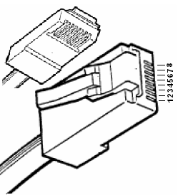
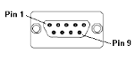
Connection Details
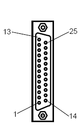
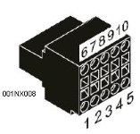
Illustrations below show the various end-of-cable connectors required:
| 25-Pin D-Type Male | 10-Pin Weidmuller
Cage Clamp |
8-Pin RJ 45 Plug | 9-Pin DB Male |
|
|
|
|
| CN1 | CN1 | MJ1/MJ2 | Port 1 |
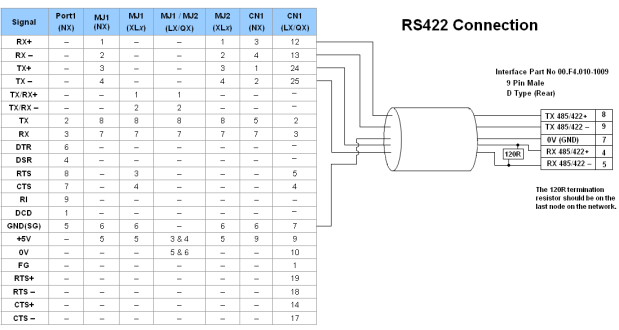
Port 1 — DB9 (Female at OCS end)
MJ1/MJ2 — RJ45 (Female at OCS end)
CN1 — 10-Pin Weidmuller Cage Clamp (Female at OCS end)
CN1 — DB25 (Female at OCS end)
NOTES:
-
Do not connect to unlisted pins.
-
Recommended Cable: Beldon 9503, twisted multipair, screened.
-
Connect the screens together at the shield / earth pin of the PLC.
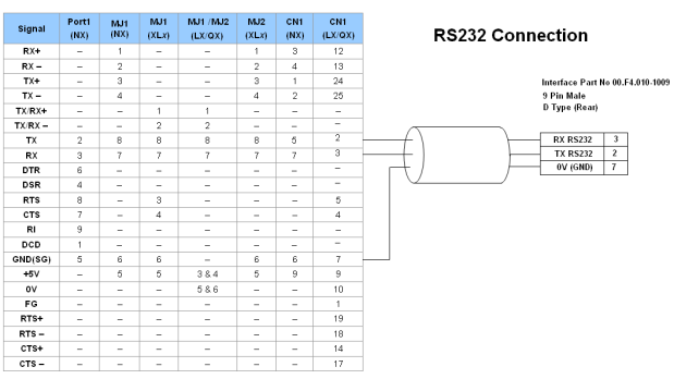