Indramat SIS Protocol
See also: Help for Serial Protocols
Overview
The Indramat SIS serial downloadable protocol is for communication between the Indramat SIS drives and an OCS. This is a Master/Slave protocol.
CSCAPE Configuration
To configure OCS for the IndramatSIS.dll protocol, select the Protocol Configuration from the Program menu in CSCAPE software. Select the appropriate protocol type on the desired port. To make sure that the Software is able to configure the equipment for the correct protocol, ensure IndramatSIS.dll file is in the Protocols directory of the current working/open Cscape.
Serial Port Format
The default link settings are : 9600 baud, No parity, Eight data bits and RS232 communication mode.
Baud Rate can be changed via the P-0-4021 parameter.
Station Node Address
The station node address for the drive is specified as selected by the switches on the drive, and can changed by accessing the P-0-4022 parameter.
Commands
Each drive parameter is accessed as described in the Parameter Access manual available from Bosch-Rexroth. When these commands are being accessed in CSCAPE the name of each parameter can be directly accessed and the lists and strings accessed via its appropriate method in Cscape Protocol Configuration.
A Protocol Configuration step-by-step guide for CSCAPE is given later in this help.
Description of Register Types
Parameters - These register types access all parameters as numeric entries. Twelve options are available to the user. S-0 Parameter, S-7 Parameter, P-0 Parameter and P-7 Parameter as well as their maximum and minimum values that are stored in the drive.
DWORD Lists ( 4-Byte Variable Lists)
This type of register contains all the parameters that have its format as 4-Byte variable lists. There are 18 of them in all and they are accessed as follows:
|
List Number |
Parameter ID |
Description |
|
0 |
P-0-72 |
CAM Shaft Profile 1 |
|
1 |
P-0-92 |
CAM Shaft Profile 2 |
|
2 |
P-0-132 |
Switch ON Threshold Position Switch |
|
3 |
P-0-133 |
Swtich OFF Threshold Position Switch |
|
4 |
P-0-177 |
Absolute Encoder buffer 1 |
|
5 |
P-0-178 |
Absolute Encoder buffer 2 |
|
6 |
P-0-193 |
Error Recoder, Operation Hours Control Selection |
|
7 |
P-0-355 |
DISC - Register Logic Task |
|
8 |
P-0-356 |
DISC - Register Drive Task |
|
9 |
P-0-357 |
DISC - Register Event Task |
|
10 |
P-0-386 |
DISC - Data Storage |
|
11 |
P-0-4006 |
Process Block target position |
|
12 |
P-0-4007 |
Process Block Velocity |
|
13 |
P-0-4008 |
Process Block acceleration |
|
14 |
P-0-4009 |
Process block Jerk |
|
15 |
P-0-4058 |
Amplifier type data |
|
16 |
P-0-4059 |
Brake Resistor data |
|
17 |
P-0-4063 |
Process Block Deceleration |
In order to access positions in these lists one selects the List number and enters it in the HIBYTE of the location (i.e. before the .). Then the position in the list is selected in the LOBYTE value (after the .) e.g. to access the first DWORD of P-0-177, enter 4.0 in the location field.
WORD Lists ( 2-Byte Variable Lists)
This type of register contains all the parameters that have its format as 2-Byte variable lists. There are 38 of them in all and they are accessed as follows:
|
List Number |
Parameter ID |
Description |
|
0 |
S-0-16 |
Custom Amplifier telegram Configuration List |
|
1 |
S-0-17 |
IDN-List of all Operation Data |
|
2 |
S-0-18 |
IDN-List of operation data for CP2 |
|
3 |
S-0-19 |
IDN-List of operation data fr CP3 |
|
4 |
S-0-21 |
IDN-List of invalid op. data for Comm Phase 2 |
|
5 |
S-0-22 |
IDN-List of invalid op. data for Comm Phase 3 |
|
6 |
S-0-24 |
Config. List of the master data telegram |
|
7 |
S-0-25 |
IDN-List of procedure commands |
|
8 |
S-0-26 |
Configuration List, Signal Status Word |
|
9 |
S-0-27 |
Configuration List, Signal Control Word |
|
10 |
S-0-187 |
List of configurable data in the AT |
|
11 |
S-0-188 |
List of configurable data in the MDT |
|
12 |
S-0-192 |
IDN-List of backup operation data |
|
13 |
S-0-279 |
IDN-List of password-protected operation data |
|
14 |
S-0-292 |
List of all operating Modes |
|
15 |
S-0-328 |
Assign list, Signal Status Word |
|
16 |
S-0-329 |
Assign list, Signal Control Word |
|
17 |
S-0-370 |
Configuration List for MDT data container |
|
18 |
S-0-371 |
Configuration List for the AT data container |
|
19 |
S-0-375 |
List of diagnostic numbers |
|
20 |
S-0-398 |
IDN-List of configurable data in the Signal Status Word |
|
21 |
S-0-399 |
IDN-List of configurable data in the Signal Control Word |
|
22 |
P-0-134 |
Position Switch lead times |
|
23 |
P-0-149 |
List of selectable signals for oscilloscope functions |
|
24 |
P-0-192 |
Error Recorder, Diagnostic Message |
|
25 |
P-0-225 |
Probe, IDN-List Signal selection |
|
26 |
P-0-352 |
DISC - Program Logic Task |
|
27 |
P-0-353 |
DISC - Program Drive Task |
|
28 |
P-0-354 |
DISC - Program Event Task |
|
29 |
P-0-358 |
DISC - Event Condition |
|
30 |
P-0-362 |
DISC - Compiler Message |
|
31 |
P-0-426 |
Analog Outputs, IDN List of assignable parameters |
|
32 |
P-0-435 |
List of configurable data digital inputs |
|
33 |
P-0-436 |
List of configurable data digital outputs |
|
34 |
P-0-437 |
List of EcoX slave drives |
|
35 |
P-0-603 |
Position Switch, Control Drives |
|
36 |
P-0-762 |
Master Axis Generator, Signal Selection List |
|
37 |
P-0-4019 |
Process Block Mode |
BYTE Lists ( 1-Byte Variable Lists or ASCII Stings)
This type of register contains all the parameters that have its format as 1-Byte variable lists or ASCII Strings. There are 10 of them in all and they are accessed as follows:
|
List Number |
Parameter ID |
Description |
|
0 |
S-0-30 |
Manufacturer Version |
|
1 |
S-0-95 |
Diagnostic Message |
|
2 |
S-0-140 |
Controller Type |
|
3 |
S-0-141 |
Motor Type |
|
4 |
S-0-142 |
Application Type |
|
5 |
S-0-143 |
SERCOS Interface Version |
|
6 |
S-0-267 |
Password |
|
7 |
S-7-141 |
Motor Type(Default) |
|
8 |
P-0-4088 |
Serial Number |
|
9 |
P-0-4089 |
Production Index |
Description of the DLL for use with the OCS range in CSCAPE
This section explains the DLL that is used to access data available with the Indramat SIS protocol.
In the Scan List when a parameter is added a window pops up the various options available for accessing.
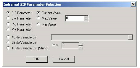
The S-0, S-7, P-0 and P-7 Parameters can be selected using the radio buttons. The min and max value are of course accessible.
The Lists are by default, grayed out. But when selected, a drop down list of each of the lists is available. The item is the offset in to the list with which the user wants to access.
Network Communication Errors
In order to access the Network statistics, user must assign the “Network status register” in network configuration. The table below gives the details of statistics.
| Number | Statistics | Location | Description |
|---|---|---|---|
|
|
|
|
|
|
1 |
Update interval exceeded count |
%Rx |
This register explains number of times that the actual transaction scan time to complete all transactions exceeded specified update interval. Generally used as an indicator that an excessive number of triggered transfers or failed communication retries are occurring that is lengthening the expected transaction scan time.
If the Update interval is set to zero (update as fast as possible), this 32-bit register alternately specifies the actual transaction scan time in mSec resolution. |
|
2 |
No response count |
%R(x+2) |
This register explains number of times that a device(s) did not respond to a transaction. This includes ALL failed transaction, not just those after the retry count is exceeded. |
|
3 |
Corrupt Response Count |
%R(x+4) |
This register explains number of times that a device(s) returned an invalid or failed response to a transaction. This includes ALL failed.
Transaction, not just those after the retry count is exceeded. |
|
4 |
Valid Response Count |
%R(x+6) |
This register explains total number of valid responses. |
NOTE: %Rx: 32-bit network status register configured in Network configuration. For example: %R500(501).
Device Communication Errors
| Error | Error Number | Description |
|---|---|---|
|
INVALID_BLOCK |
-203 |
Invalid size for data type. |
|
NO_RESPONSE_FROM_PLC |
-204 |
Timeout while waiting for remote node response. |
|
INVALID_RESPONSE_FROM_PLC |
-205 |
Corrupted response from remote node. |
|
INVALID_INITIALISATION |
-207 |
Internal Error - Unable to open port. |
Connection Details
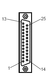
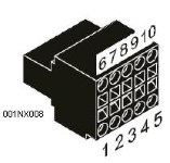
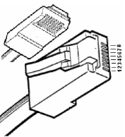
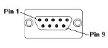
Illustrations below show the various end-of-cable connectors required:
| 25-Pin D-Type Male | 10-Pin Weidmuller
Cage Clamp |
8-Pin RJ 45 Plug | 9-Pin DB Male |
|
|
|
|
| CN1 | CN1 | MJ1/MJ2 | Port 1 |
Connection details (OCS to Bosch-RexRoth EcoDrive using the Indramat SIS Protocol)
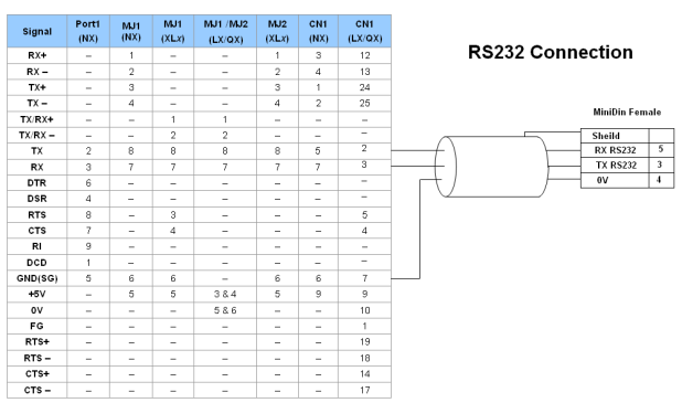
Port 1 — DB9 (Female at OCS end)
MJ1/MJ2 — RJ45 (Female at OCS end)
CN1 — 10-Pin Weidmuller Cage Clamp (Female at OCS end)
CN1 — DB25 (Female at OCS end)
NOTES:
-
Do not connect to unlisted pins.
-
Recommended Cable: Beldon 9503, twisted multipair, screened.
-
Connect the screens together at the shield / earth pin of the PLC.