GPS Downloadable Protocol
See also: Help for Serial Protocols
Overview
The worldwide Global Positioning System ( GPS) consists of a set of earth-orbiting satellites and ground stations. GPS allows a portable receiver (plane, ship, car, hand-held) to calculate to a high degree of accuracy it's current position and other similar information. More than two dozen GPS satellites are in medium Earth orbit, transmitting signals allowing GPS receivers to determine the receiver's location, speed and direction. The position of the receiver can be determined any time, anywhere, in any weather by knowing its distance from three or more satellites. The calculation of the position of the receiver is achieved by knowing the precise location of the satellites at any given time and the time taken for a radio signal to reach the receiver from each of the satellites. The position of the receiver is given in latitude, longitude and altitude. The precise location of each satellite is determined in a similar manner using the stationary ground stations.
GPS module transmits this data in NMEA 0183 format. GPS downloadable protocol supports following NEMA 0183 messages:
-
Global Positioning System Fix Data ( GGA).
-
Recommended Minimum Specific GPS/TRANSIT Data ( RMC)
GPS NMEA 0183 protocol tested successfully with GARMIN GPS 18 LVC, 5m.
CSCAPE Configuration
To configure OCS for the GPS protocol, select the Protocol Configuration from the Program menu in CSCAPE software. Select the appropriate protocol type in desired port. To make sure that the Software is able to configure the equipment for the correct protocol, make sure GPS.dll file is in the Protocols directory of the current working/open Cscape.
Serial Port Configuration
The communication settings (fixed) are: 4800 baud, 8 data bits, no parity, 1 stop bit, No handshaking and RS232 Communications mode.
Entering GPS Data
The following data will be populated starting from the PLC register specified by the user:
|
Reg Offset |
Data Name |
Size in Words |
Data Type |
Range |
|
0 |
Latitude Degree |
1 |
Unsigned Integer |
0-360 |
|
1 |
Latitude Minute |
1 |
Unsigned Integer |
0-60 |
|
2 |
Latitude Seconds |
1 |
Unsigned Integer |
0-60 |
|
3 |
Latitude Hemi Sphere |
1 |
ASCII Character |
‘ N’ or ‘ E’ or ‘ W’ or ‘S’ |
|
4 |
Longitude Degree |
1 |
Unsigned Integer |
0-360 |
|
5 |
Longitude Minute |
1 |
Unsigned Integer |
0-60 |
|
6 |
Longitude Seconds |
1 |
Unsigned Integer |
0-60 |
|
7 |
Longitude Hemi Sphere |
1 |
ASCII Character |
‘ N’ or ‘ E’ or ‘ W’ or ‘S’ |
|
8 |
Current Day |
1 |
Unsigned Integer |
1-31 |
|
9 |
Current Month |
1 |
Unsigned Integer |
1-12 |
|
10 |
Current Year |
1 |
Unsigned Integer |
2000 - 2099 |
|
11 |
Current Second |
1 |
Unsigned Integer |
00 - 59 |
|
12 |
Current Minute |
1 |
Unsigned Integer |
00 – 59 |
|
13 |
Current Hour |
1 |
Unsigned Integer |
00 – 23 |
|
14 |
GPS Quality |
1 |
Unsigned Integer |
0 – 6 0 = fix not available 1 = Non-differential GPS fix available 2 = Differential GPS ( WAAS) fix available 6 = Estimated |
|
15 |
Number Of satellites in view |
1 |
Unsigned Integer |
0 - 12 |
|
16 |
Horizontal Dilution of Precision |
2 |
Signed Integer 32bit |
Represented as: 5 – 999 Actual Data :0.5-99.9 |
|
18 |
Antenna height above/below mean sea level |
2 |
Signed Integer 32bit |
Represented as : -99999 to 999999 Actual Data :- 9999.9 to 99999.9 meters |
|
20 |
Geoidal height |
2 |
Signed Integer 32bit |
Represented as : -9999 to 99999 Actual Data : -999.9 to 9999.9 meters |
|
22 |
Speed over ground |
2 |
Signed Integer 32bit |
Represented as : 0 to 9999 Actual Data : 000.0 to 999.9 knots |
|
24 |
Course over ground |
2 |
Signed Integer 32bit |
Represented as : 0 to 3599 Actual Data : 000.0 to 359.9 degrees |
|
26 |
Latitude Seconds (Non Truncated) |
1 |
Unsigned Integer |
Represented as : 0 to 59999 Actual Data : 00.0 to 59.999 seconds |
|
27 |
Longitude Seconds (Non Truncated) |
1 |
Unsigned Integer |
Represented as : 0 to 59999 Actual Data : 00.0 to 59.999 seconds |
Network Communication Errors
In order to access the Network statistics, user must assign the “Network status register” in network configuration. The table below gives the details of statistics.
| Number | Statistics | Location | Description |
|---|---|---|---|
|
|
|
|
|
|
1 |
Update interval exceeded count |
%Rx |
This register explains number of times that the actual transaction scan time to complete all transactions exceeded specified update interval. Generally used as an indicator that an excessive number of triggered transfers or failed communication retries are occurring that is lengthening the expected transaction scan time.
If the Update interval is set to zero (update as fast as possible), this 32-bit register alternately specifies the actual transaction scan time in mSec resolution. |
|
2 |
No response count |
%R(x+2) |
This register explains number of times that a device(s) did not respond to a transaction. This includes ALL failed transaction, not just those after the retry count is exceeded. |
|
3 |
Corrupt Response Count |
%R(x+4) |
This register explains number of times that a device(s) returned an invalid or failed response to a transaction. This includes ALL failed.
Transaction, not just those after the retry count is exceeded. |
|
4 |
Valid Response Count |
%R(x+6) |
This register explains total number of valid responses. |
NOTE: %Rx: 32-bit network status register configured in Network configuration. For example: %R500(501).
Device Communication Errors
| Error | Error Number | Description |
|---|---|---|
|
INVALID_BLOCK |
-203 |
Invalid size for data type. |
|
NO_RESPONSE_FROM_PLC |
-204 |
Timeout while waiting for remote node response. |
|
INVALID_RESPONSE_FROM_PLC |
-205 |
Corrupted response from remote node. |
|
INVALID_INITIALISATION |
-207 |
Internal Error - Unable to open port. |
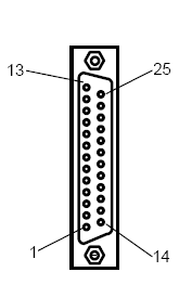
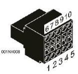
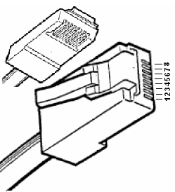
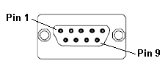
Connection Details
Illustrations below show the various end-of-cable connectors required:
| 25-Pin D-Type Male | 10-Pin Weidmuller
Cage Clamp |
8-Pin RJ 45 Plug | 9-Pin DB Male |
|
|
|
|
| CN1 | CN1 | MJ1/MJ2 | Port 1 |
GPS Device Connection
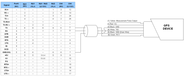
Port 1 — DB9 (Female at OCS end)
MJ1/MJ2 — RJ45 (Female at OCS end)
CN1 — 10-Pin Weidmuller Cage Clamp (Female at OCS end)
CN1 — DB25 (Female at OCS end)
NOTES:
-
Do not connect to unlisted pins.
-
Recommended Cable: Beldon 9503, twisted multipair, screened.
-
Connect the screens together at the shield / earth pin of the PLC.
GPS183 connection to OCS serial ports
|
Pin |
Color |
GPS183 Signal |
|
2 |
Red |
Supply Voltage In (5V) |
|
3 |
Black |
Signal Common (0V) |
|
4 |
White |
Transmit Data Out ( TXD) |
|
5 |
Black |
Supply Voltage Common (0V) |
|
6 |
Green |
Receive Data In ( RXD) |