Eurotherm 631/635/637 Series Servo Drives
See also: Help for Serial Protocols
Overview
The Eurotherm635 serial downloadable protocol is for communication between the Eurotherm drive and an OCS. This is a Master/Slave protocol.
CSCAPE Configuration
To configure OCS for the Eurotherm635 protocol, select the Protocol Configuration from the Program menu in CSCAPE software. Select the appropriate protocol type on the desired port. To make sure that the Software is able to configure the equipment for the correct protocol, make sure the Eurotherm635.dll file is in Protocols directory of the current working/open Cscape.
Serial Port Configuration
The default settings are: 4800 baud, 7 data bits, Even parity, 1 stop bit, RS232 communication and No handshaking. For communications, the connector may be wired as RS232 or RS485.
Node Number
Inverter Axis Number (network Address) are required only when connected to COM2.
Selecting Device Register
Enter the desired name for slave.
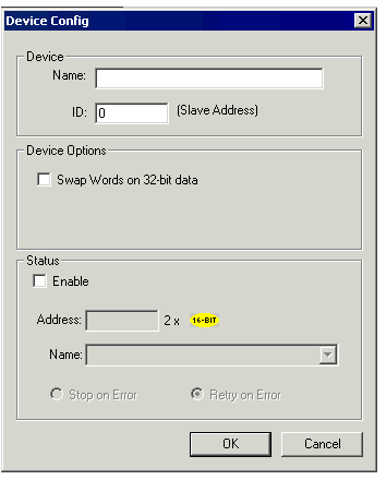
Enter the desired parameter address in the Device Register field or use " > "button to select the desired parameter from the drop-down list.
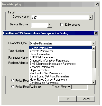
Parameter Specification
Data is accessed in several different ways with the Servo Drive :
-
Write Only Registers/Commands/Parameters. As these are write only, when embedded on the display it will always display as “0”. However, if edited the value entered will be transferred to the Servo.
-
Some Write Only Commands do not involve data at all. Here the action of editing and accepting (with the enter key) will cause the command to be sent.
-
As some data is only readable in a table form, an offset into the table has to be specified. If one parameter is edited the whole table is read, the appropriate parameter is modified and then the whole table is written.
-
Some commands allow multiple tables to be accessed. In this case the table and the offsets must be specified in the form “TTT.OO”. Where the table is “TTT” and the offset is “OO”.
-
Some register types are only accessible if the Drive is disabled see the tables below. If attempts are made to write to these registers when the drive is enabled the data field on the display will show *****. This will remain until a different menu page is selected.
NOTE: The tables below show how the data can be accessed.
Data Access
Disable – Disables the Servo Drive
This is a Write only command. “0” will always be displayed and any form of editing of this register type and accepting will issue the command.
Activate – Enables the Servo Drive.
This is a Write only command. “0” will always be displayed and any form of editing of this register type and accepting will issue the command.
Reset – Reset the Servo Drive.
This is a Write only command. “0” will always be displayed and any form of editing of this register type and accepting will issue the command. This command will only work and be successful if the Drive is enabled.
EEPROM – Stores the Servo Drives Parameters in EEPROM.
This is a Write only command. “0” will always be displayed and any form of editing of this register type and accepting will issue the command. This command will only work and be successful if the Drive is Disabled.
Diagnostic Information
This is a read only command any attempt to write will cause a comms failure.
|
Location |
Size |
Description |
|
0 |
16 Bit |
Error Word (see manual for details) |
|
1 |
16 Bit |
Status Word (see manual for details) |
|
2 |
16 Bit |
Operating Mode Low Byte / Input Definition High Byte |
|
3 |
16 Bit |
Actual Speed at Scaling 1 |
|
4 |
16 Bit |
Input State Low Byte / Output State High Byte |
|
5 |
32 Bit |
Actual position |
|
6 |
32 Bit |
Reserved |
BIAS Diagnostic Information
This is a read only command except for Offset 0 any attempt to write to any others will cause a comms failure.
|
Location |
Size |
Description |
|
0 |
16 Bit |
BIAS Execution pointer |
|
1 |
16 Bit |
PLC execution pointer |
|
2 |
16 Bit |
Block Number at Strobe |
|
3 |
16 Bit |
BIAS Stack |
|
4 |
16 Bit |
Wait Time |
|
5 |
16 Bit |
BIAS status (see manual for details) |
|
6 |
16 Bit |
PLC status (see manual for details) |
|
7 |
16 Bit |
PLC stack |
|
8 |
32 Bit |
Actual position 1 |
|
9 |
32 Bit |
Actual position 2 |
|
10 |
32 Bit |
Actual Position 3 (CAN bus absolute encoder) |
|
11 |
32 Bit |
Reserved |
Variables
The drive requires firmware version 4.18 or greater to be able to write to the variables.
|
Location |
Size |
Description |
|
0.00 |
32 Bit |
Variable Group 0 No. 0 |
|
0.01 |
32 Bit |
Variable Group 0 No. 1 |
|
0.02 |
32 Bit |
Variable Group 0 No. 2 |
|
.. |
.. |
.. |
|
0.15 |
32 Bit |
Variable Group 0 No. 15 |
|
1.00 |
32 Bit |
Variable Group 1 No. 0 |
|
1.01 |
32 Bit |
Variable Group 1 No. 1 |
|
.. |
.. |
.. |
|
1.15 |
32 Bit |
Variable Group 1 No. 15 |
|
.. |
.. |
.. |
|
15.15 |
32 Bit |
Variable Group 15 No. 15 |
Flags
Flags are single bit types. If one bit is read it will be stored in the least significant bit of the TIUs word. If several are read they are packed into 16 words in the TIU. The drive requires firmware version 4.18 or greater to be able to write to the flags.
|
Location |
Size |
Description |
|
0.00 |
1 Bit |
Flag Group 0 No. 0 |
|
0.01 |
1 Bit |
Flag Group 0 No. 1 |
|
0.02 |
1 Bit |
Flag Group 0 No. 2 |
|
.. |
.. |
.. |
|
0.63 |
1 Bit |
Flag Group 0 No. 63 |
|
1.00 |
1 Bit |
Flag Group 1 No. 0 |
|
1.01 |
1 Bit |
Flag Group 1 No. 1 |
|
.. |
.. |
.. |
|
1.63 |
1 Bit |
Flag Group 1 No. 63 |
|
.. |
.. |
.. |
|
3.63 |
1 Bit |
Flag Group 3 No. 63 |
Start Position Set
This Write only command activates the position block. For this to work the drive must be in positioning regulation mode and be active. The position blocks must be set before this can be used. The drive requires firmware version 4.12 or greater.
|
Location |
Size |
Description |
|
0 |
16 Bit |
Positioning block (0-9) |
Serial Speed Setpoint
This Write only command activates the given value as a speed setpoint. For this to work the drive must be in speed control without analogous set point value mode.
|
Location |
Size |
Description |
|
0 |
16 Bit |
Speed setpoint in rpm (+/- 4000) |
Motor Rated Current
In order to write this command, the drive must be in disabled mode.
|
Location |
Size |
Description |
|
0 |
16 Bit |
Rated motor current ( value = rated current * √2 * 100) |
Configuration Parameters
This command will only work and be successful if the Drive is Disabled.
|
Location |
Size |
Description |
|
0 |
8 Bit |
Network Axis number used for COM2 (1 to 255) (station number/node id) Only written if connected to COM1 (X15). |
|
1 |
16 Bit |
Configuration word (see manual for details) |
|
2 |
16 Bit |
Operating Mode Low byte (0 to 5) / Input Definition High Byte |
|
3 |
16 Bit |
Rated Motor Current * 100 * Ö2 |
|
4 |
16 Bit |
Pole Pair number (1-6) |
|
5 |
16 Bit |
EMC/100 min –1 in Volts |
|
6 |
16 Bit |
Motor inductance in 1/10 mH |
|
7 |
16 Bit |
Motor resistance in 1/10 Ohm |
|
8 |
16 Bit |
I2t-monitoring time of the motor in seconds |
|
9 |
16 Bit |
NTC-resistance T1 in Ohm |
|
10 |
16 Bit |
NTC-resistance T2 in Ohm |
|
11 |
16 Bit |
PTC-resistance in Ohm |
|
12 |
16 Bit |
Regulator disabled deceleration value (0-3) |
|
13 |
16 Bit |
Ucc-low threshhold in Volts |
|
14 |
16 Bit |
Ucc-ballast threshold in Volts |
|
15 |
16 Bit |
Ballast resistance in 1/10 Ohm |
|
16 |
16 Bit |
Ballast Power in Watts |
Speed Controller Parameters
|
Location |
Size |
Description |
|
0 |
16 Bit |
List place P-component |
|
1 |
16 Bit |
List place I-component |
|
2 |
16 Bit |
Maximum current in 3.125% steps |
|
3 |
16 Bit |
Setpoint zero window in 1.22 mV steps |
|
4 |
16 Bit |
Setpoint integrator in 10 rpm/s |
|
5 |
16 Bit |
Speed setpoint norming in 0.1 rpm |
|
6 |
16 Bit |
Current setpoint norming 0.001 ampere |
|
7 |
16 Bit |
Nominal measuring point 1 in rpm |
|
8 |
16 Bit |
Nominal measuring point 1 in 0.01 ampere |
|
9 |
16 Bit |
Nominal external current limiting in 0.01 Volt |
|
10 |
16 Bit |
Setpoint offset correction value in 1.22 mV steps |
Current Controller Parameters
|
Location |
Size |
Description |
|
0 |
16 Bit |
List place P-component |
|
1 |
16 Bit |
List place I-component |
|
2 |
16 Bit |
Reserved |
|
3 |
16 Bit |
Reserved |
|
4 |
16 Bit |
Reserved |
|
5 |
16 Bit |
Reserved |
|
6 |
16 Bit |
Offset resolver position |
|
7 |
16 Bit |
Ucc overvoltage threshold in Volts |
|
8 |
16 Bit |
Reserved |
Position Controller Parameters
|
Location |
Size |
Description |
|
0 |
16 Bit |
Nominal speed at scaling 1 |
|
1 |
16 Bit |
Acceleration at scaling 2 |
|
2 |
16 Bit |
Deceleration at scaling 2 |
|
3 |
16 Bit |
“Position Reached” - window at incr. |
|
4 |
16 Bit |
P-component |
|
5 |
16 Bit |
I-component |
|
6 |
16 Bit |
Reserved |
Position Set
|
Location |
Size |
Description |
|
0.00 |
8 Bit |
Operating Mode (Set 0) |
|
0.01 |
16 Bit |
Nominal Speed at scaling 1 (Set 0) |
|
0.02 |
16 Bit |
Acceleration at scaling 2 (Set 0) |
|
0.03 |
16 Bit |
Deceleration at scaling 2 (Set 0) |
|
0.04 |
16 Bit |
“Position Reached” - window at incr. (Set 0) |
|
0.05 |
32 Bit |
Nominal position in increments (Set 0) |
|
.. |
.. |
.. |
|
9.00 |
8 Bit |
Operating Mode (Set 9) |
|
9.01 |
16 Bit |
Nominal Speed at scaling 1 (Set 9) |
|
9.02 |
16 Bit |
Acceleration at scaling 2 (Set 9) |
|
9.03 |
16 Bit |
Deceleration at scaling 2 (Set 9) |
|
9.04 |
16 Bit |
“Position Reached” - window at incr. (Set 9) |
|
9.05 |
32 Bit |
Nominal position in increments (Set 9) |
Cam Profile
Profile setup for profiles 0 to 15
|
Location |
Size |
Description |
|
0.00 |
16 Bit |
Reserved for EASYRIDER Low byte / number of correction (always 0) High byte |
|
0.01 |
16 Bit |
Number of profile points (PP) |
|
0.02 |
16 Bit |
Address of first profile point (STS) |
|
0.03 |
16 Bit |
Reserved |
|
0.04 |
16 Bit |
Correction value 1. Stage (always 0) |
|
0.05 |
16 Bit |
Correction value 2. Stage (always 0) |
|
0.06 |
16 Bit |
Correction value 3. Stage (always 0) |
|
0.07 |
16 Bit |
Correction value 4. Stage (always 0) |
|
0.08 |
16 Bit |
Correction value 5. Stage (always 0) |
|
0.09 |
16 Bit |
Correction value 6. Stage (always 0) |
|
0.10 |
16 Bit |
Correction value 7. Stage (always 0) |
|
0.11 |
16 Bit |
Correction value 8. Stage (always 0) |
|
0.12 |
16 Bit |
Correction value 9. Stage (always 0) |
|
0.13 |
16 Bit |
Correction value 10. Stage (always 0) |
|
0.14 |
32 Bit |
Master stroke (MT) |
|
0.15 |
32 Bit |
Slave stroke (ST) |
|
0.16 |
32 Bit |
Reserved |
|
0.17 |
32 Bit |
Reserved |
|
0.18 |
32 Bit |
Reserved |
|
0.19 |
32 Bit |
Reserved |
|
0.20 |
32 Bit |
Syncro mode (identification of calculated profile; 255 for user defined) (TY) Low byte |
|
0.21 |
32 Bit |
Reserved |
|
0.22 |
32 Bit |
Reserved |
|
.. |
.. |
.. |
|
15.13 |
16 Bit |
Correction value 10. Stage (always 0) |
|
15.14 |
32 Bit |
Master stroke (MT) |
|
15.15 |
32 Bit |
Slave stroke (ST) |
|
15.16 |
32 Bit |
Reserved |
|
15.17 |
32 Bit |
Reserved |
|
15.18 |
32 Bit |
Reserved |
|
15.19 |
32 Bit |
Reserved |
|
15.20 |
32 Bit |
Syncro mode (identification of calculated profile; 255 for user defined) (TY) Low byte |
|
15.21 |
32 Bit |
Reserved |
|
15.22 |
32 Bit |
Reserved |
Profile Point Block
Profile Point setup for profile Points 0 to 255
|
Location |
Size |
Description |
|
0.00 |
8 Bit |
Profile Block 0 point 0 |
|
0.01 |
8 Bit |
Profile Block 0 point 1 |
|
0.02 |
8 Bit |
Profile Block 0 point 2 |
|
0.03 |
8 Bit |
Profile Block 0 point 3 |
|
0.04 |
8 Bit |
Profile Block 0 point 4 |
|
0.05 |
8 Bit |
Profile Block 0 point 5 |
|
0.06 |
8 Bit |
Profile Block 0 point 6 |
|
0.07 |
8 Bit |
Profile Block 0 point 7 |
|
.. |
.. |
.. |
|
255.01 |
8 Bit |
Profile Block 255 point 1 |
|
255.02 |
8 Bit |
Profile Block 255 point 2 |
|
255.03 |
8 Bit |
Profile Block 255 point 3 |
|
255.04 |
8 Bit |
Profile Block 255 point 4 |
|
255.05 |
8 Bit |
Profile Block 255 point 5 |
|
255.06 |
8 Bit |
Profile Block 255 point 6 |
|
255.07 |
8 Bit |
Profile Block 255 point 7 |
I/O Definition
|
Location |
Size |
Description |
|
0 |
8 Bit |
Definition I X10.2 |
|
1 |
8 Bit |
Definition I X10.4 |
|
2 |
8 Bit |
Definition I X10.11 |
|
3 |
8 Bit |
Definition I X10.14 |
|
4 |
8 Bit |
Definition I X10.15 |
|
5 |
8 Bit |
Definition I X10.24 |
|
6 |
8 Bit |
Definition I X10.25 |
|
7 |
8 Bit |
Definition O X10.12 |
|
8 |
8 Bit |
Definition O X10.13 |
|
9 |
8 Bit |
Definition O X10.20 |
|
10 |
8 Bit |
Definition O X10.23 |
BIAS PROGRAM
Allows access to the BIAS Program ONLY when the drive is disabled. Only Set numbers 0 to 655 are available at present.
|
Location |
Size |
Description |
|
0.00 |
8 Bit |
BIAS Set Number 0 – BIAS Command Code |
|
0.01 |
8 Bit |
BIAS Set Number 0 – BIAS Command data byte 1 |
|
0.02 |
8 Bit |
BIAS Set Number 0 – BIAS Command data byte 2 |
|
0.03 |
8 Bit |
BIAS Set Number 0 – BIAS Command data byte 3 |
|
0.04 |
8 Bit |
BIAS Set Number 0 – BIAS Command data byte 4 |
|
0.05 |
8 Bit |
BIAS Set Number 0 – BIAS Command data byte 5 |
|
0.06 |
8 Bit |
BIAS Set Number 0 – BIAS Command data byte 6 |
|
0.07 |
8 Bit |
BIAS Set Number 0 – BIAS Command data byte 7 |
|
.. |
.. |
.. |
|
655.00 |
8 Bit |
BIAS Set Number 655 – BIAS Command Code |
|
655.01 |
8 Bit |
BIAS Set Number 655 – BIAS Command data byte 1 |
|
655.02 |
8 Bit |
BIAS Set Number 655 – BIAS Command data byte 2 |
|
655.03 |
8 Bit |
BIAS Set Number 655 – BIAS Command data byte 3 |
|
655.04 |
8 Bit |
BIAS Set Number 655 – BIAS Command data byte 4 |
|
655.05 |
8 Bit |
BIAS Set Number 655 – BIAS Command data byte 5 |
|
655.06 |
8 Bit |
BIAS Set Number 655 – BIAS Command data byte 6 |
|
655.07 |
8 Bit |
BIAS Set Number 655 – BIAS Command data byte 7 |
Network Communication Errors
In order to access the Network statistics, user must assign the “Network status register” in network configuration. The table below gives the details of statistics.
| Number | Statistics | Location | Description |
|---|---|---|---|
|
|
|
|
|
|
1 |
Update interval exceeded count |
%Rx |
This register explains number of times that the actual transaction scan time to complete all transactions exceeded specified update interval. Generally used as an indicator that an excessive number of triggered transfers or failed communication retries are occurring that is lengthening the expected transaction scan time.
If the Update interval is set to zero (update as fast as possible), this 32-bit register alternately specifies the actual transaction scan time in mSec resolution. |
|
2 |
No response count |
%R(x+2) |
This register explains number of times that a device(s) did not respond to a transaction. This includes ALL failed transaction, not just those after the retry count is exceeded. |
|
3 |
Corrupt Response Count |
%R(x+4) |
This register explains number of times that a device(s) returned an invalid or failed response to a transaction. This includes ALL failed.
Transaction, not just those after the retry count is exceeded. |
|
4 |
Valid Response Count |
%R(x+6) |
This register explains total number of valid responses. |
NOTE: %Rx: 32-bit network status register configured in Network configuration. For example: %R500(501).
Device Communication Errors
| Error | Error Number | Description |
|---|---|---|
|
INVALID_BLOCK |
-203 |
Invalid size for data type. |
|
NO_RESPONSE_FROM_PLC |
-204 |
Timeout while waiting for remote node response. |
|
INVALID_RESPONSE_FROM_PLC |
-205 |
Corrupted response from remote node. |
|
INVALID_INITIALISATION |
-207 |
Internal Error - Unable to open port. |
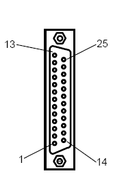
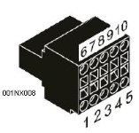
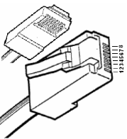
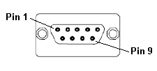
Connection Details
Illustrations below show the various end-of-cable connectors required:
| 25-Pin D-Type Male | 10-Pin Weidmuller
Cage Clamp |
8-Pin RJ 45 Plug | 9-Pin DB Male |
|
|
|
|
| CN1 | CN1 | MJ1/MJ2 | Port 1 |
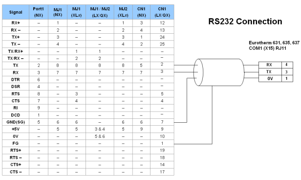
Port 1 — DB9 (Female at OCS end)
MJ1/MJ2 — RJ45 (Female at OCS end)
CN1 — 10-Pin Weidmuller Cage Clamp (Female at OCS end)
CN1 — DB25 (Female at OCS end)
NOTES:
-
Do not connect to unlisted pins.
-
Recommended Cable: Beldon 9503, twisted multipair, screened.
-
Connect the screens together at the shield / earth pin of the PLC.
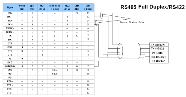