EC Motor Protocol
See also: Help for Serial Protocols
Overview
The ECMotor serial downloadable protocol is for communication between the EC Motor and an OCS. This is a Master/Slave protocol.
CSCAPE Configuration
To configure OCS for the EC Motor protocol, select the Protocol Configuration from the Program menu in CSCAPE software. Select the appropriate protocol type on the desired port. To make sure that the Software is able to configure the equipment for the correct protocol, make sure the ECMotorProtocol.dll file is in Protocols directory of the current working/open Cscape.
Serial Port Configuration
The default link settings for the terminal are : 9600 baud, No parity, Eight data bits, One stop bit, RS232 communication and No handshaking.
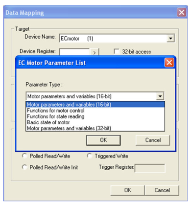
Selecting Device Register
Enter the desired parameter address in the Device Register field or click " > " button to view the parameter range details.
EC Drive Parameters
|
Parameter/command Name |
Parameter/ Command reference |
Note |
Size |
|
InputOutputword |
0.40 |
Bit accessible – Read/Write |
NA |
|
Def_OfSourcesForSWProtection |
0.44 |
Bit accessible – Read/Write |
|
|
CommunicationStatusWord |
0.48 |
Bit accessible – Triggered Read |
|
|
ControlWord |
0.52 |
Bit accessible – Read/Write |
|
|
ErrorStatusWord |
0.56 |
Bit accessible – Triggered Read |
|
|
WorkingStatusWord |
0.60 |
Bit accessible – Read |
|
|
ProfileGenPosition |
4.64 |
Motor Variables Read only |
Signed 32 |
|
ProfileGenVelocity |
0.68 |
Signed 16 |
|
|
ActualPosition |
4.72 |
Signed 32 |
|
|
SensorAngle |
4.76 |
Signed 32 |
|
|
ActualVelocity |
0.80 |
Signed 16 |
|
|
ActualCurrentIq |
0.84 |
Signed 16 |
|
|
DCLineVoltage |
0.88 |
Unsigned 16 |
|
|
TemperatureOfElectronics |
0.92 |
Unsigned 16 |
|
|
MotorUtilisation |
0.96 |
Unsigned 16 |
|
|
PositionError |
0.100 |
Signed 16 |
|
|
SystemTime |
4.128 |
Motor Variables Read/Write |
Unsigned 32 |
|
LowPositionLimit |
4.132 |
Signed 32 |
|
|
HighPositionLimit |
4.136 |
Signed 32 |
|
|
RequestedPosition |
4.140 |
Signed 32 |
|
|
RequestedVelocity |
0.144 |
Signed 16 |
|
|
RequestedAccleration |
0.148 |
Unsigned 16 |
|
|
RequestedDeceleration |
0.152 |
Unsigned 16 |
|
|
RequestedTorqueLimit |
0.156 |
Signed 16 |
|
|
Communication |
0.188 |
Unsigned 16 |
|
|
URAM00 |
0.192 or 4.192 |
Polled Read/Write |
16-bit or 32-bit User defined |
|
URAM01 |
0.196 or 4.196 |
||
|
URAM02 |
0.200 or 4.200 |
||
|
URAM03 |
0.204 or 4.204 |
||
|
URAM04 |
0.208 or 4.208 |
||
|
URAM05 |
0.212 or 4.212 |
||
|
URAM06 |
0.216 or 4.216 |
||
|
URAM07 |
0.220 or 4.220 |
||
|
URAM08 |
0.224 or 4.224 |
||
|
URAM09 |
0.228 or 4.228 |
||
|
URAM10 |
0.232 or 4.232 |
||
|
URAM11 |
0.236 or 4.236 |
||
|
URAM12 |
0.00 or 4.00 |
||
|
URAM13 |
0.04 or 4.04 |
||
|
URAM14 |
0.08 or 4.08 |
||
|
URAM15 |
0.12 or 4.12 |
||
|
URAM16 |
0.16 or 4.16 |
||
|
URAM17 |
0.20 or 4.20 |
||
|
URAM18 |
0.24 or 4.24 |
||
|
URAM19 |
0.28 or 4.28 |
||
|
URAM20 |
0.32 or 4.32 |
||
|
ServiceMode_debug |
1.00 |
Write only |
Unsigned 8 |
|
PowerStageOFF |
1.01 |
Unsigned 8 |
|
|
DecelarateToSTOP |
1.02 |
Unsigned 8 |
|
|
PowerStageON_Standstill |
1.03 |
Unsigned 8 |
|
|
TorqueMode |
1.04 |
Unsigned 8 |
|
|
VelocityMode |
1.05 |
Unsigned 8 |
|
|
PositionMode |
1.06 |
Unsigned 8 |
|
|
PotentiometerVelocityControl |
1.15 |
Unsigned 8 |
|
|
ARROWVelocityProfile |
1.16 |
Write only |
Unsigned 8 |
|
MavetOldLabeler |
1.17 |
Unsigned 8 |
|
|
MavetNewLabeler |
1.18 |
Unsigned 8 |
|
|
VyskovSX_VYS |
1.19 |
Unsigned 8 |
|
|
VyskovSX_VYL |
1.20 |
Unsigned 8 |
|
|
Old debug mode |
1.28 |
Write only |
Unsigned 8 |
|
Error state |
1.29 |
Unsigned 8 |
|
|
Debug mode |
1.30 |
Unsigned 8 |
|
|
HW reset of motor |
1.31 |
Unsigned 8 |
|
|
ClearErrorStates |
1.32 |
Write only – register content will be ignored |
NA |
|
ClearPositionWhenMotorStops |
1.33 |
||
|
ClearPositionWhenMotorRun |
1.34 |
||
|
ClearPositionAbsolutelyPlus |
1.35 |
||
|
ClearPositionAbsolutelyMinus |
1.36 |
||
|
RunUserPrgTask1 |
1.51 |
Write only – lower 8-bit addr must be present in reg |
NA |
|
StopUserPrgTask1 |
1.52 |
Write only – register content will be ignored |
|
|
RunUserPrgTask2 |
1.53 |
Write only – lower 8-bit addr must be present in reg |
|
|
StopUserPrgTask2 |
1.54 |
Write only – register content will be ignored |
|
|
ReadFirmwareVersion |
1.60 |
Unsigned 16 |
|
|
GetMotorStatus |
2.00 |
Reads data in 3 consecutive words starting from the specified register. * refer EC motor doc for parameter list. See the following "Functions for state reading" section for more details. |
NA |
|
GetGeneratorValues |
2.01 |
Reads data in 3 consecutive double words starting from the specified register. * refer EC motor doc for parameter list (16-bit parameter will be stored in 32-bit little endian format.) See the following "Functions for state reading" section for more details. |
NA |
|
GetRequestedValues |
2.02 |
Reads data in 5 consecutive double words starting from the specified register. * refer EC motor doc for parameter list (16-bit parameter will be stored in 32-bit little endian format). See the following "Functions for state reading" section for more details. |
NA |
|
GetStatusValues |
2.03 |
Reads data in 6 consecutive words starting from the specified register. * refer EC motor doc for parameter list. See the following "Functions for state reading" section for more details. |
NA |
|
GetMeasuredValues1 |
2.04 |
Reads data in 6 consecutive double words starting from the specified register. * refer EC motor doc for parameter list (16-bit parameter will be stored in 32-bit little endian format). See the following "Functions for state reading" section for more details. |
NA |
|
GetMeasuredValues2 |
2.05 |
Reads data in 7 consecutive words starting from the specified register. * refer EC motor doc for parameter list. See the following "Functions for state reading" section for more details. |
NA |
|
SX (basic state of motor) |
3.00 |
bit3 Error – any warning cause error (power state is off) – Read only |
NA |
|
bit2 Warning – any warning is indicated – Read only |
NA |
||
|
bit1 User flag – state of user flag, controlled by user program – Read only |
NA |
||
|
bit0 Input BIO – state of "fast" input – Read only |
NA |
||
Functions for State Reading
|
GET_STATUS_MOTOR |
%Rx |
%Rx+1 |
%Rx+2 |
%Rx+3 |
||||||
|
DL |
d1 |
d2 |
d3 |
d4 |
d5 |
d6 |
d7 |
d8 |
||
|
MA: |
GET_STATUS_MOTOR |
2 |
||||||||
|
EC: |
confirm |
6 |
m_ssm |
m_sss |
c_sss |
|||||
%R is in Word type
|
GET_GENERATOR_VALUES |
%Rx |
%Rx+1 |
%Rx+2 |
%Rx+3 |
%Rx+4 |
%Rx+5 |
|||||||||
|
DL |
d1 |
d2 |
d3 |
d4 |
d5 |
d6 |
d7 |
d8 |
d9 |
d10 |
d11 |
d12 |
|||
|
MA: |
GET_GENERATOR_VALUES |
2 |
|
|
|||||||||||
|
EC: |
confirm |
8 |
p_acx |
p_vex |
p_pox |
||||||||||
%R is Dword for alignment purpose
|
GET_REQUESTED_VALUES |
%Rx |
%Rx+1 |
%Rx+2 |
%Rx+3 |
%Rx+4 |
%Rx+5 |
%Rx+6 |
%Rx+7 |
%Rx+8 |
%Rx+9 |
||||||||||||
|
DL |
d1 |
d2 |
d3 |
d4 |
d5 |
d6 |
d7 |
d8 |
d9 |
d10 |
d11 |
d12 |
d13 |
d14 |
d15 |
d16 |
d17 |
d18 |
d19 |
d20 |
||
|
MA: |
GET_REQUESTED_VALUES |
2 |
|
|
|
|
||||||||||||||||
|
EC: |
confirm |
12 |
p_mon |
p_dec |
p_acc |
p_ven |
p_pon |
|||||||||||||||
%R is Dword for alignment purpose
|
GET_STATUS_VALUES |
%Rx |
%Rx+1 |
%Rx+2 |
%Rx+3 |
%Rx+4 |
%Rx+5 |
||||||||
|
DL |
d1 |
d2 |
d3 |
d4 |
d5 |
d6 |
d7 |
d8 |
d9 |
d10 |
d11 |
d12 |
||
|
MA: |
GET_STATUS_VALUES |
2 |
||||||||||||
|
EC: |
confirm |
12 |
udc |
tsn |
tcu |
c_sss |
u_pc1 |
u_pc2 |
||||||
%R is in Word type
|
GET_MEASURED_VALUES1 |
%Rx |
%Rx+1 |
%Rx+2 |
%Rx+3 |
%Rx+4 |
%Rx+5 |
%Rx+6 |
%Rx+7 |
%Rx+8 |
%Rx+9 |
%Rx+10 |
%Rx+11 |
||||||||||||||
|
DL |
d1 |
d2 |
d3 |
d4 |
d5 |
d6 |
d7 |
d8 |
d9 |
d10 |
d11 |
d12 |
d13 |
d14 |
d15 |
d16 |
d17 |
d18 |
d19 |
d20 |
d21 |
d22 |
d23 |
d24 |
||
|
MA: |
GET_MEASURED_VALUES1 |
2 |
|
|
|
|
|
|||||||||||||||||||
|
EC: |
confirm |
14 |
m_ssm |
m_sss |
udc |
iq_ref |
h_vel |
h_poz |
||||||||||||||||||
%R is Dword for alignment purpose
|
GET_MEASURED_VALUES2 |
%Rx |
%Rx+1 |
%Rx+2 |
%Rx+3 |
%Rx+4 |
%Rx+5 |
%Rx+6 |
|||||||||
|
DL |
d1 |
d2 |
d3 |
d4 |
d5 |
d6 |
d7 |
d8 |
d9 |
d10 |
d11 |
d12 |
d13 |
d14 |
||
|
MA: |
GET_MEASURE.D_VALUES2 |
2 |
||||||||||||||
|
EC: |
confirm |
14 |
h_poz (hi) |
h_vel |
p_acx |
iq_ref |
m_ssm |
m_sss |
c_sss |
|||||||
%R is in Word type
Network Communication Errors
In order to access the Network statistics, user must assign the “Network status register” in network configuration. The table below gives the details of statistics.
| Number | Statistics | Location | Description |
|---|---|---|---|
|
|
|
|
|
|
1 |
Update interval exceeded count |
%Rx |
This register explains number of times that the actual transaction scan time to complete all transactions exceeded specified update interval. Generally used as an indicator that an excessive number of triggered transfers or failed communication retries are occurring that is lengthening the expected transaction scan time.
If the Update interval is set to zero (update as fast as possible), this 32-bit register alternately specifies the actual transaction scan time in mSec resolution. |
|
2 |
No response count |
%R(x+2) |
This register explains number of times that a device(s) did not respond to a transaction. This includes ALL failed transaction, not just those after the retry count is exceeded. |
|
3 |
Corrupt Response Count |
%R(x+4) |
This register explains number of times that a device(s) returned an invalid or failed response to a transaction. This includes ALL failed.
Transaction, not just those after the retry count is exceeded. |
|
4 |
Valid Response Count |
%R(x+6) |
This register explains total number of valid responses. |
NOTE: %Rx: 32-bit network status register configured in Network configuration. For example: %R500(501).
Device Communication Errors
| Error | Error Number | Description |
|---|---|---|
|
INVALID_BLOCK |
-203 |
Invalid size for data type. |
|
NO_RESPONSE_FROM_PLC |
-204 |
Timeout while waiting for remote node response. |
|
INVALID_RESPONSE_FROM_PLC |
-205 |
Corrupted response from remote node. |
|
INVALID_INITIALISATION |
-207 |
Internal Error - Unable to open port. |
Connection Details
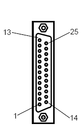
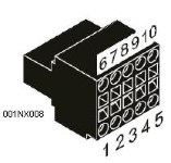
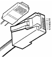
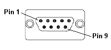
Illustrations below show the various end-of-cable connectors required:
| 25-Pin D-Type Male | 10-Pin Weidmuller
Cage Clamp |
8-Pin RJ 45 Plug | 9-Pin DB Male |
|
|
|
|
| CN1 | CN1 | MJ1/MJ2 | Port 1 |
OCS and EC Motor drive are connected with galvanical isolation using an isolation module EC113 or it’s variants.
This module is separately powered in the connected diagram between the EC113 and an OCS as shown below:
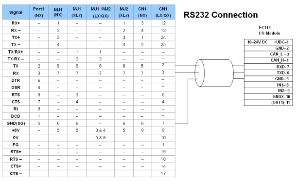
Port 1 — DB9 (Female at OCS end)
MJ1/MJ2 — RJ45 (Female at OCS end)
CN1 — 10-Pin Weidmuller Cage Clamp (Female at OCS end)
CN1 — DB25 (Female at OCS end)
NOTES:
-
Do not connect to unlisted pins.
-
Recommended Cable: Beldon 9503, twisted multipair, screened.
-
Connect the screens together at the shield / earth pin of the PLC.
This module is separately powered in the connected diagram between the EC100 and an OCS as shown below:
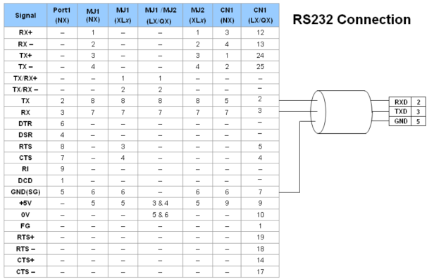
Port 1 — DB9 (Female at OCS end)
MJ1/MJ2 — RJ45 (Female at OCS end)
CN1 — 10-Pin Weidmuller Cage Clamp (Female at OCS end)
CN1 — DB25 (Female at OCS end)
NOTES:
-
Do not connect to unlisted pins.
-
Recommended Cable: Beldon 9503, twisted multipair, screened.
-
Connect the screens together at the shield / earth pin of the PLC.