Allen Bradley DF1 v.4.00
See also: Help for Serial Protocols
Overview
DF1 protocol is typically available through CH0 or a communications I/O module on an Allen-Bradley PLCs. This driver provides support for a sub-set of the DF1 commands, which accesses data tables on the PLC.
The DF1 serial downloadable protocol is for communication between the DF1 and an OCS. This is a Master/Slave protocol.
The Operator Station DF1 protocol supports all models of Allen-Bradley PLC’s. It gives access to Allen-Bradley Data Highway, Allen-Bradley Data Highway Plus and Allen-Bradley DH485 Networks via appropriate Allen Bradley network modules.
Features
-
Indication of failed transaction (if device status register configured).
-
Support for either SLC500 or PLC5 communications.
-
Support for Full Duplex mode only.
-
Support for RS232 peer-to-peer only
-
Support for CRC error check mode only.
-
Support for optional parity.
Device Status
If the device status register is enabled and a transaction fails, a value is written to the status register.
-201 - Internal error
-202 - Internal error
-204 - Timeout, slave device did not respond.
-205 - Invalid response, PLC returned an error message or message failed CRC check.
Virtual 32-bit transfers
When 32-bit access is selected from the Data Mapping menu for a specific transaction, any local change to either of the two local OCS registers associated with a virtual 32-bit point causes both register values to be written to the remote device in the same transaction (assumes either Read/Write or Read/Write/Init type configuration).
CSCAPE Configuration
To configure OCS for the DF1 protocol, select the Protocol Configuration from the Program menu in CSCAPE software. Select the appropriate protocol type in desired port. To make sure that the Software is able to configure the equipment for the correct protocol, ensure AB_DF1.dll file is in the Protocols directory of the current working/open Cscape.
Serial Port Configuration
The default link settings for the terminal are : 19200 baud, No parity, Eight data bits, One stop bit, RS232 communication and No handshaking.
Selecting Device Register
Enter the desired parameter address in the Device Register field or click > button to view the parameter range details.
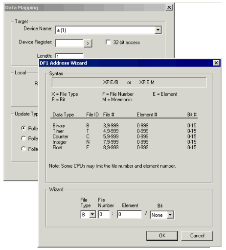
Register Ranges
Version 1.04 Supports master only operation to the slave PLC.
The current implementation supports only 3 Level addressing and not full 4 Level. This means that the data files containing timers and counters only return the Control Word and not the preset and current values. To access the preset and current values map them to the integer Data file in the PLC, which is then accessible to the Operator Station.
Link Configuration
The Operator Station must always be a master device on the link, and does not accept requests made on it. Version 1.03 and upwards of the protocol assumes the following characteristics of the DF1 node to which it is connected:
-
CRC error checking (not selectable) for added data security
-
Full Duplex Operation (not selectable)
Other parameters may be required at the Allen Bradley Controller, which are less critical but have been configured on the Operator Station these are:
| Duplicate Packet Detection |
Location |
| ACK | 50ms |
| No Handshake | No |
| NAK | 3 |
| ENQ | 3 |
| Embedded Response |
Autodetect |
Serial Link Format
Care should be taken to match both ends of the link for baud rate and parity. The default setting for the Operator Station being 9600 baud with eight data bits, one stop bit and no parity. In addition ensure that the DF1 node connected to has handshaking lines disabled. Refer to your Allen Bradley documentation for details on configuring the DF1 port on the device to which the Operator Station is to be connected.
The protocol supports the read unprotected registers and write unprotected registers commands of the DF1 basic command set (PLC2 Command Set). These commands give access to data tables within the various PLCs in the range. In addition SLC500 Registers (applicable to the SLC500 and MicroLogix) and SLC500 Float (Floating point table) are supported.
Connection to an Allen-Bradley Series 5 PLC
When DF1 is used in implementing a connection to a PLC5, only one datafile may be accessed in the PLC. Where multiple PLCs are being accessed on a network the data file identifier must be the same for all PLCs accessed.
After selecting the target data file, it is specified in the Cscape Software project by modifying the Target Data File value, under the communication settings. The Target Data File field will only appear when the remote equipment model is set to PLC5.
When accessing PLC5s the data block size is in words and the start address is in bytes, hence to access the seventh word in a data block it is necessary to select a start address of fourteen when operating the terminal with a PLC5.
The target data file should be created as being of integer type and should contain sufficient elements to support all the reads and writes which will be directed at the specified PLC. If the data file does not exist in the target PLC, or is of insufficient size to support an individual transaction, a 'BAD' transaction will occur.
Two possibilities exist for connection to a PLC5. Some PLC5 models are fitted with a DF1 port as standard, others of the PLC5 range require a networking module for either data highway or data highway plus.
Direct connection to the PLC5
The following PLC5 models are fitted as standard with a port capable of supporting DF1 commands:
-
PLC5/11
-
PLC5/20
-
PLC5/30
-
PLC5/40
-
PLC5/60
Connection to PLC5's via Data Highway/Data Highway Plus
The following PLC5 models do not have a DF1 port fitted as standard, they do however have a Data Highway Plus port fitted as standard. The Operator Station can be connected to these PLCs via a 1770-KF2 module:
-
PLC5/10
-
PLC5/12
-
PLC5/15
-
PLC5/25
Connecting to the MicroLogix Range
The Micro range unprotected reads and unprotected writes occur within data file 7. This data file should be created as being of integer type and should contain sufficient elements to support all the reads and writes directed at the specific PLC. The available range is N7:0 to N7:255
If data file 7 does not exist in the target PLC or is of insufficient size to support an individual transaction a 'BAD' transaction will occur.
Alternatively a specific data file can be accessed using “Specific Registers” the data file and register being specified as shown below.
| Data Type |
Location Value |
Register Addressed |
|---|---|---|
| Unprotected (Data File 7) | 1 | Register 1 of data file 7 |
| Specific Register | 5.025 | Register 25 of data file 5 |
Network Communication Errors
In order to access the Network statistics, user must assign the “Network status register” in network configuration. The table below gives the details of statistics.
| Number | Statistics | Location | Description |
|---|---|---|---|
|
|
|
|
|
|
1 |
Update interval exceeded count |
%Rx |
This register explains number of times that the actual transaction scan time to complete all transactions exceeded specified update interval. Generally used as an indicator that an excessive number of triggered transfers or failed communication retries are occurring that is lengthening the expected transaction scan time.
If the Update interval is set to zero (update as fast as possible), this 32-bit register alternately specifies the actual transaction scan time in mSec resolution. |
|
2 |
No response count |
%R(x+2) |
This register explains number of times that a device(s) did not respond to a transaction. This includes ALL failed transaction, not just those after the retry count is exceeded. |
|
3 |
Corrupt Response Count |
%R(x+4) |
This register explains number of times that a device(s) returned an invalid or failed response to a transaction. This includes ALL failed.
Transaction, not just those after the retry count is exceeded. |
|
4 |
Valid Response Count |
%R(x+6) |
This register explains total number of valid responses. |
NOTE: %Rx: 32-bit network status register configured in Network configuration. For example: %R500(501).
Device Communication Errors
| Error | Error Number | Description |
|---|---|---|
|
INVALID_BLOCK |
-203 |
Invalid size for data type. |
|
NO_RESPONSE_FROM_PLC |
-204 |
Timeout while waiting for remote node response. |
|
INVALID_RESPONSE_FROM_PLC |
-205 |
Corrupted response from remote node. |
|
INVALID_INITIALISATION |
-207 |
Internal Error - Unable to open port. |
Connection Details
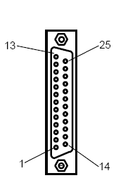
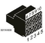
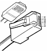
Illustrations below show the various end-of-cable connectors required:
| 25-Pin D-Type Male | 10-Pin Weidmuller
Cage Clamp |
8-Pin RJ 45 Plug | 9-Pin DB Male |
|
|
|
|
| CN1 | CN1 | MJ1/MJ2 | Port 1 |
Connection details to Toshiba T Series PLC’s/ Toshiba T2 Series PLC’s/ Toshiba T2N PLC’s (RS232)
RS232 Connection - Allen Bradley
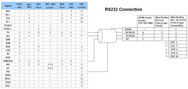
Port 1 — DB9 (Female at OCS end)
MJ1/MJ2 — RJ45 (Female at OCS end)
CN1 — 10-Pin Weidmuller Cage Clamp (Female at OCS end)
CN1 — DB25 (Female at OCS end)
NOTES:
-
Do not connect to unlisted pins.
-
Recommended Cable: Beldon 9503, twisted multipair, screened.
-
Connect the screens together at the shield / earth pin of the PLC.
RS422 Connection - Allen Bradley
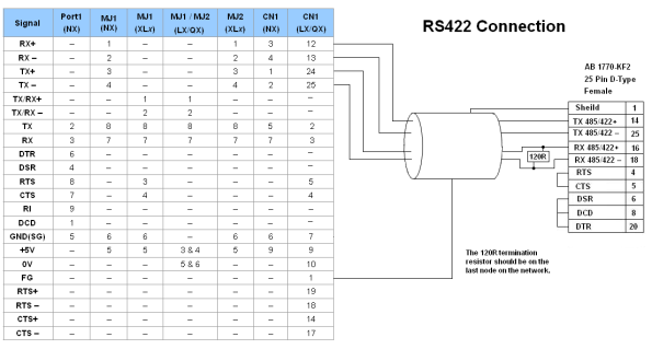
Port 1 — DB9 (Female at OCS end)
MJ1/MJ2 — RJ45 (Female at OCS end)
CN1 — 10-Pin Weidmuller Cage Clamp (Female at OCS end)
CN1 — DB25 (Female at OCS end)
NOTES:
-
Do not connect to unlisted pins.
-
Recommended Cable: Beldon 9503, twisted multipair, screened.
-
Connect the screens together at the shield / earth pin of the PLC.