BACnet MSTP Protocol
The BACnet IP Server Protocol
BACnet is a data communication protocol for building automation and control networks.
Note: This protocol is supported in XL4e/XL7e/EXL10e/EXL6e/X5, ZX, RCC, XLPlus.
BACnet stack services supported
The BACnet stack currently implements the following services listed in the table. We plan to add the rest of the services as we go. With the services that are implemented, User can build a BACnet device that meets the standardized profile for a BACnet Smart Sensor, BACnet Smart Actuator, or a BACnet Application Specific Controller.
| BACnet Service | Initiate | Execute |
|---|---|---|
| Who Is | - | Yes |
| I Am | Yes | Yes |
| Who Has | Yes | Yes |
| I Have | Yes | Yes |
| Read Property | Yes | Yes |
| Write Property | Yes | Yes |
| Read Property Multiple | Yes | Yes |
| Write Property Multiple | - | Yes |
BACnet Object Supported
- Device
- Analog Value
- Analog Output
- Analog Input
- Digital Value
- Digital Input
- Digital Output
BACnet Server Address mapping for OCS and supported functions
Mandatory Parameters for the Device object
- Object Identifier - As per the BACnet specification 2 << 22 + index – e.g 0x02000010 for node Id 16.
- Object Name - Model Series name. e.g. XL4e
- Object Type - An enumerated type ‘device’ with value 8
- System Status - An enumerated value which can show the values 0, ‘operational’; 1, ‘operational read only’; 2, ‘download required’: 3, ‘download in progress’: 4, ‘non operational’: 5, ‘backup required’.
- Vendor Name - Horner APG LLC
- Vendor Identifier - The Vendor Identifier allocated to Horner, 600.
- Model Name - A string eg. “XC1E3” The Model Number of the product. i.e. XC1E3
- Firmware Revision - Firmware Version in the format "xx.yy". e.g. 12.96
- Application Software Revision - Internal firmware rev.
- Protocol Services Supported - A bit string with 40 bits (5 bytes) with bits set for I Am, I Have, Who Has, Who Is, readProperty, readPropertyMultiple, writeProperty, writePropertyMultiple, 0x00 0xD0, 0x01, 0x06, 0x03
- Protocol Object Types Supported - A bit string with 50 bits with bits set for Analog Value, Analog Input, Analog Output, Digital Value, Digital Input, Digital Output and Device.
- Object List - A BACnet array containing Analog Value, Analog Input, Analog Output and Device
- MAX APDU length supported - Unsigned; MSTP 480; BACnet/IP 1476
- Segmentation supported - 3 – no segmentation
- APDU timeout - Unsigned – Defaults to 3000, can be changed.
- APDU retries - Unsigned – Defaults to 3, can be changed.
- Device Address Binding - empty.
- Database Revision - 0
Mandatory Parameters for the Analog Value objects
- Object Identifier - Encoded as per the BACnet specification 2 << 22 + index – e.g. 0x00800064 for %R100
- Object Name - A string e.g. “%R100”
- Object Type - An enumerated type ‘analog-value’ enumerated value 2
- Present Value - The value in the %R Register encoded as a real number Real -32768.0 to -32767.0
- Status Flags - A bit string containing 4 zeros, Not used currently.
- EventState - An enumerated value indicating ‘normal’ – enumerated value 0
- OutOfService - A boolean – Always FALSE.
- Engineering Units - An enumerated value indicating ‘No Units’ - enumerated value 95.
- Description - A string eg. "Retentive Register of BACnet Server"
Mandatory Parameters for the Analog Input objects
- Object Identifier - e.g. %AI4
- Object Name - A string e.g. “%AI4”
- Object Type - An enumerated type ‘analog-input’ enumerated value 0
- Present Value - The value in the %AI Register encoded as a real number Real -32768.0 to -32767.0
- Status Flags - A bit string containing 4 zeros, Not used currently.
- EventState - An enumerated value indicating ‘normal’ – enumerated value 0
- OutOfService - A boolean – Always FALSE.
- Engineering Units - An enumerated value indicating ‘No Units’ - enumerated value 95.
- Description - A string eg. "%AI4"
Mandatory Parameters for the Analog Output objects
- Object Identifier - e.g. %AQ4
- Object Name - A string e.g. “%AQ4”
- Object Type - An enumerated type ‘analog-output’ enumerated value 1
- Present Value - The value in the %AQ Register encoded as a real number Real -32768.0 to -32767.0
- Status Flags - A bit string containing 4 zeros, Not used currently.
- EventState - An enumerated value indicating ‘normal’ – enumerated value 0
- OutOfService - A boolean – Always FALSE.
- Engineering Units - An enumerated value indicating ‘No Units’ - enumerated value 95.
- Description - A string eg. "%AQ4"
Mandatory Parameters for the Digital Value objects
- Object Identifier - e.g. Object_Binary_Value :100
- Object Name - A string e.g. “%M100”
- Object Type - An enumerated type ‘digital-value’ enumerated value 5
- Present Value - The value in the %M Register Boolean 0 or 1.
- Status Flags - A bit string containing 4 zeros, Not used currently.
- EventState - An enumerated value indicating ‘normal’ – enumerated value 0
- OutOfService - A boolean – Always FALSE.
- Description - A string eg. "%M100"
Mandatory Parameters for the Digital Input objects
- Object Identifier - e.g. Object_Binary_Input :100
- Object Name - A string e.g. “%I100”
- Object Type - An enumerated type ‘digital-input’ enumerated value 3
- Present Value - The value in the %I Register Boolean 0 or 1.
- Status Flags - A bit string containing 4 zeros, Not used currently.
- EventState - An enumerated value indicating ‘normal’ – enumerated value 0
- OutOfService - A boolean – Always FALSE.
- Description - A string eg. "%I100"
Mandatory Parameters for the Digital Output objects
- Object Identifier - e.g. Object_Binary_Output :100
- Object Name - A string e.g. “%Q100”
- Object Type - An enumerated type ‘digital-output’ enumerated value 4
- Present Value - The value in the %Q Register Boolean 0 or 1.
- Status Flags - A bit string containing 4 zeros, Not used currently.
- EventState - An enumerated value indicating ‘normal’ – enumerated value 0
- OutOfService - A boolean – Always FALSE.
- Description - A string eg. "%Q100"
CSCAPE Configuration
To configure Controller for the BACnet MSTP Server Protocol, select the Protocol Configuration from the Program menu in CSCAPE software. Select the appropriate protocol type on the desired port. To make sure that the Software is able to configure the controller for the correct protocol, ensure dll file is in the Protocols directory of the current working/open Cscape.
Config all Network details by pressing "Network" button in "protocol Config" Dialog Box.
Serial Port settings & status Registers settings.
Network Configuration
Note: From Cscape 9.90 SP3 and firmware 15.40 onwards, disable network feature has been added in protocol network configuration. This option is used to close the port and disable the protocol configured in that particular port. Single Bit register has to be configured to use this function. Setting the bit high closes the port and disables the protocol. OCS will not send any serial packets from this port until the bit is high. Setting the bit low will reopen the port and enables the protocol again.
Configuring Device
All Timeout's & BACnet Device settings can be configured by pressing the button "Configure Device Options" Button.
Device status Registers states, It occupies 3 consecutive registers:
- %Rx: GoodDataCount (32-bit) --> Good Data Frame sent Count.
- %R(x+2): DEV_ID (16-Bit) --> Local Device ID.
- %R(x+3): MASTER_Station_ID (16-Bit) --> station ID of data previously sent to MASTER DATA request.
Configuring Device Options
Set MAC address and MAX MAC address along with timing parameters. Tturnaround is grayed out as it is NOT used right now.
Pressing the Default button sets the default BACnet recommended settings.
- Nmax_info_frames:This parameter represents the value of the Max_Info_Frames property of the node's Device object. The value of Max_Info_Frames specifies the maximum number of information frames the node may send before it must pass the token. Max_Info_Frames may have different values on different nodes. This may be used to allocate more or less of the available link bandwidth to particular nodes. Default value shall be 1.
- Nmax_master:This parameter represents the value of the Max_Master property of the node's Device object. The value of Max_Master specifies the highest allowable address for master nodes. The value of Max_Master shall be less than or equal to 127. Default value shall be 127.
- MAC Address:MAC for Master Nodes can only have address 0-127
- Apdu Timeout:The APDU_Timeout property, of type Unsigned, shall indicate the amount of time in milliseconds between retransmissions of an APDU requiring acknowledgment for which no acknowledgment has been received. A suggested default value for this property is 60,000 milliseconds for devices that permit modification of this parameter.
- Npoll:The number of tokens received or used before a Poll For Master cycle is executed.
- Nretry_token:The number of retries on sending Token.
- Nmin_octets:The minimum number of DataAvailable or ReceiveError events that must be seen by a receiving node in order to declare the line "active".
- Tframe_abort:The minimum time without a DataAvailable or ReceiveError event within a frame before a receiving node may discard the frame: 60 bit times. (Implementations may use larger values for this timeout, not to exceed 100 milliseconds.)
- Tfreame_gap:The maximum idle time a sending node may allow to elapse between octets of a frame the node is transmitting(n bit times).
- Tno_token:The time without a DataAvailable or ReceiveError event before declaration of loss of token: 500 milliseconds.
- Tpostdrive: The maximum time after the end of the stop bit of the final octet of a transmitted frame before a node must disable its driver: 15 bit times.
- Treply_delay:The maximum time a node may wait after reception of a frame that expects a reply before sending the first octet of a reply or Reply Postponed frame: 250 milliseconds.
- Treply_timeout:The minimum time without a DataAvailable or ReceiveError event that a node must wait for a station to begin replying to a confirmed request.
- Troff: Repeater turnoff delay. The duration of a continuous logical one state at the active input port of an MSTP repeater after which the repeater will enter the IDLE state: 29 bit times < Troff < 40 bit times.
- Tslot: The width of the time slot within which a node may generate a token: 10 milliseconds.
- Tturnaround: The minimum time after the end of the stop bit of the final octet of a received frame before a node may enable its driver: 40 bit times.
- Tusage_delay:The maximum time a node may wait after reception of the token or a Poll For Master frame before sending the first octet of a frame: 15 milliseconds.
- Tusage_timeout:The minimum time without a DataAvailable or ReceiveError event that a node must wait for a remote node to begin using a token or replying to a Poll For Master frame: 20 milliseconds.
Note: From Cscape 9.90 SP3 and firmware 15.40 onwards, disable device feature has been added in protocol device configuration. This option is used to disable a particular slave configured in the network. Single bit register has to be configured to use this function. Setting the bit high disables the slave and OCS will not send any serial packets only to this slave until the bit is high. Setting the bit low enables the communication with the slave again.
Configuring Scan List
The user can configure the required Data types and length in the above dialog box. The limitation for each data type is below:
Analog Values – 5000
Analog Input – 256
Analog Output – 256
Digital Values – 1000
Digital Inputs – 256
Digital Outputs – 256
Network Communication Errors
In order to access the Network statistics, user must assign the “Network status register” in network configuration. It occupies 16 consecutive registers. The table below gives the details of statistics.
| Number | Statistics | Location | Description |
|---|---|---|---|
| 1 |
Reserved |
%Rx |
Reserved |
| 2 |
NoFrameCount |
%R(x+2) |
This register explains number of times that a device(s) did not respond to a transaction. This includes ALL failed transaction, not just those after the retry count is exceeded. |
| 3 |
BadFrameCount |
%R(x+4) |
This register explains number of times that a device(s) returned an invalid or failed response to a transaction. This includes ALL failed transaction, not just those after the retry count is exceeded. |
| 4 |
GoodFrameCount |
%R(x+6) |
This register explains total number of valid responses. |
| 5 |
TotalTokenPassed |
%R(x+8) | This register counts total Token passed to another Node. |
| 6 |
ErrorCode |
%R(x+10) | This Register Displays Last Error Code Encountered by last BAD Frame. |
| 7 |
This_Station |
%R(x+12) | This Register indicates MAC ID of BACnet Server. |
| 8 |
Next_Station |
%R(x+14) | This Register Indicates MAC ID of the next Node in the Network to which the BACnet Server Passed the token. |
Note: %Rx: 32-bit network status register configured in Network configuration. For example: %R500.
ErrorCodes(%R(x+10)) are:
| ERR_NO | 0 |
| ERR_BAD_CRC | 1 |
| ERR_BAD_INDEX | 2 |
| ERR_FRAME_TIMEOUT | 3 |
| ERR_FRAME_ERROR | 4 |
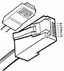
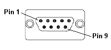
Connection details (Illustrations below show the various end-of-cable connectors required)
| 8-Pin RJ 45 Plug | 9-Pin DB Male |
|
|
| MJ2/MJ3 |
NPort 2 |
Following table indicates the Summary of the Serial port pin details for Serial communication. With this information RS-2485 communication cables can be done.
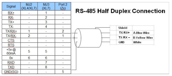
Note:
- Do not connect unlisted pins.
- Recommended cable: Beldon 9503, twisted multipair, screened.
- Connect the screens together at the shield / Earth pin of the PLC.
- One Pair Tx data, one pair Rx data, one pair 0V