Protocol Configuration 
Also see: Networking and Communications
See also: Help for Serial Protocols
Topic Menu
Protocol Overview
Through loadable protocol device drivers, certain models of the OCS family can provide the ability to exchange data with remote devices such as variable-frequency drives, PLCs and remote I/O devices. This feature greatly expands the OCS ’s control capability with negligible effect on the OCS ’s ladder scan time![]() Time required for the controller to read its inputs, solve the Ladder Logic program, and write its outputs. Scan times are usually expressed in milliseconds.
NOTE: Scan times can vary, depending on number and complexity of Ladder Logic rungs that are active during the "solve" portion of the scan..
Time required for the controller to read its inputs, solve the Ladder Logic program, and write its outputs. Scan times are usually expressed in milliseconds.
NOTE: Scan times can vary, depending on number and complexity of Ladder Logic rungs that are active during the "solve" portion of the scan..
Remote devices that communicate serially must do so under certain rules of data transfer known as a protocol. Many device manufactures have created their own protocol for communications with their device. For a OCS to communicate with a specific device, it must be loaded with the corresponding serial communications protocol device driver that supports that protocol. A limited number of protocol device drivers are packaged with the Cscape distribution; however, as more are developed, they will be made available as add-on packages. A device driver is typically distributed as a Windows module, which contains the configuration menus, help files and the target executable driver code. When updating device drivers, an install routine loads the device driver to the Cscape directory structure and makes that driver available to Cscape applications.
-
Once installed, the protocol device driver can be included as part of a Cscape application by selecting it from a list of installed protocol device drivers and attaching it to the desired serial port (Home > Protocols). Only one protocol device driver can be associated with a serial port, though some OCS models support multiple protocols on a single Ethernet port.
-
Once the protocol is selected for a specific port, that port must be configured to match the bit transfer size and rate of the target device(s). This is configured under the Network Config menu, which contains port specific information such as the basic serial port parameters (i.e. baud rate, stop bits parity, retries, etc.). In addition to the serial port parameters, this menu also contains the transaction scan update control configuration and any network level protocol specific configuration.
-
Once the network is configured, each device on the serial communications network must be configured. For some communications (i.e. RS232), the network can be limited to one device. The devices are configured under the Device Config menu, which contains an arbitrary device name, the device ID and optionally a OCS status register that contains any device fault information.
-
Once each device(s) is configured, a Scan List
 A list of communications to carry out to one or more devices. Normally, the Master or Client device will execute this scan list, which is directed at Slave or Server devices. Scan List items may be Polled or Triggered. of entries must be created which defines the transfer of data between a local (OCS ) register(s) and a remote device register(s). These entries are created under the Data Mapping menu, which contains a OCS register, a target device ID, a target device register address, the number of registers to transfer, and update type.
 -
Each entry can be configured for one of two types of initiating a transaction: Polled
Polled - When a device is consistently asked for data, either as fast as possible or on a time basis. Normally associated with Modbus communications. and Triggered. Polled type entries initiate a transaction with the remote device on every transaction scan. Triggered type entries only initiate a transaction when a corresponding local (OCS ) binary trigger register is set. Once a triggered type transaction completes, the protocol device driver resets the local (OCS ) binary register to indicate completion.
These basic types are also subdivided into read or write operations. For polled operations, a Read operation only reads from a remote device. Likewise a Read/Write operation continuously reads from the remote device unless the target OCS register value changes from one ladder scan to another. In this case, the new OCS value is written to the target device. For triggered operations, only a read or write action is available.
When downloaded to the OCS , the Scan List is scanned sequentially to generate data transactions with the remote device. This transaction scanning can be on a continual basis (automatic) or controlled from ladder logic (manual) once a complex connection is created via a program. The specific transaction-scanning mode is selected from the Network Config menu.
Automatic Update (Transaction) Scanning
When placed in RUN mode, the OCS, on a periodic update basis, sequentially scans the Scan List to initiate transactions with remote devices. The user through the Update Interval parameter can optionally control the period of this transaction scan. Allowing the user to specify the Update Interval provides the ability to reduce the communication loading on some PLCs or devices. The optional network status contains a counter, which indicates the number of scans in which the actual update time exceeds the specified update interval. This counter is useful in determining if the communications is currently performing to expectations (see Network status).
If a data transfer error occurs, all other transactions with the associated device are suspended for the remainder of the transaction scan. This provides for minimal interference to other devices on a multi-device network. On the following transaction scan, the failed message is retried once. If the message completes successful, communications with that device continues as normal. However, if the message again fails, all other transactions with the associated device are suspended for the remainder of the transaction scan. Additionally, if the number of retries reaches the specified retry count, that device is placed in offline status (see Device Offline Recovery).
Manual Update (Transaction) Scanning
This method provides a mechanism that allows ladder to establish a serial connection with a remote device before starting a transactions scan (such as dial-up modem). When placed in RUN mode, the OCS scans the Scan List ONCE when the corresponding Manual Trigger register is set. Once the single scan of transactions is complete, the OCS resets the Manual Trigger register stopping further transfers and providing any necessary indication to the ladder program that the transactions are complete. Thereafter, ladder can establish the next connection and set the manual trigger to start the next transaction scan.
An optional ID Select register can be used in conjunction with the Manual Trigger to limit transactions to those Scan List entries associated to a single specific device. Ladder writes the ID of the device to scan before the trigger register is set to initiate the transaction scan. All Scan List entries associated with other devices are ignored during this transaction scan. If the ID Select register is not configured (left blank) to a OCS register in the Port Config, this option is disabled. If the ID Select register is configured, it must always be set to a specific device ID (single transaction scan that includes all device IDs is not available). If a data transfer error occurs, the error response is different from automatic update scanning in that retries are attempted immediately. Once the transaction completes successfully, scanning with device returns to normal. However, if the retry count is exhausted without success, that device is placed in offline status (see Device Offline Recovery).
Data Consistency
Since the update interval (transaction scan time![]() Time required for the controller to read its inputs, solve the Ladder Logic program, and write its outputs. Scan times are usually expressed in milliseconds.
NOTE: Scan times can vary, depending on number and complexity of Ladder Logic rungs that are active during the "solve" portion of the scan.) can and probably will exceed the ladder scan time of the OCS, the transfer of data between the OCS data registers and the remote device must be managed asynchronously. To preserve register data consistency of the OCS registers during the ladder scan, in and out going data is held in temporary buffers until the ladder scan is completed before being transferred to/from the OCS registers. While available transaction data is loaded to OCS registers at the end of each logic scan, it can take several logic scans before all the data from a single transaction scan is updated.
Time required for the controller to read its inputs, solve the Ladder Logic program, and write its outputs. Scan times are usually expressed in milliseconds.
NOTE: Scan times can vary, depending on number and complexity of Ladder Logic rungs that are active during the "solve" portion of the scan.) can and probably will exceed the ladder scan time of the OCS, the transfer of data between the OCS data registers and the remote device must be managed asynchronously. To preserve register data consistency of the OCS registers during the ladder scan, in and out going data is held in temporary buffers until the ladder scan is completed before being transferred to/from the OCS registers. While available transaction data is loaded to OCS registers at the end of each logic scan, it can take several logic scans before all the data from a single transaction scan is updated.
Device Offline Recovery
If a particular device fails to respond after the specified number of retries, it is taken offline. When a device is taken offline, an error code is written to the device status register (if enabled) and no further transactions are attempted with that device.
Two methods are available to place the device back to on-line status to re-attempt communications (Automatic timed retry (reacquire) or Manual).
-
Automatic Reacquire - If no device status register is configured <or> a device status register is configured and Retry on Error is selected (Device Config), an offline device is returned to online after a Reacquire Time interval (Port Config). If a status register is configured for the device, clearing the status register can also be used to return the device back to online status.
-
Manual - If the device status register is configured and Stop on Error is selected (Device Config), an offline device is not returned to online status after the Reacquire Time interval. In this mode, only clearing the status register returns the device back to online status. This allows ladder or the user interaction to determine when communications is re-attempted with the failed device.
When a device is returned to online status, the first entry in the Scan List associated with the failed device is scanned. If the transaction is completed successfully, the device status register is cleared (if enabled) and communications continues with that device as expected. If the transaction fails, it is retried for retry count times before being placed back into offline status.
Note: If a device status register is enabled, a device can be placed in offline status by simply writing a non-zero value to the status register.
Device Status
Device status registers can be optionally enabled and used to determine the current state of communications with a particular device on the protocol device driver’s network. To enable this option, a checkbox must be enabled and a OCS register must be specified in the device’s configuration. This OCS register specifies the starting address of 2 consecutive registers. The first register provides a protocol specific error code and the second register provides the offending Scan List index. If the device is communicating properly, the first register contains a zero value. For device specific error codes, see the protocol device drivers help file.
Network Status
Network status registers (counters) can be optionally enabled and used to determine the general health of the protocol device driver’s network. To enable this option, the starting (OCS ) register of these status counters must be specified in the Network Config menu. This register address specifies the starting address of 8 consecutive registers, which provide 4 (32bits status counters).
-
Update interval Exceeded Count [Offset+0] (32 bit) – Number of times that the actual transaction scan time to complete all transactions exceeded specified update interval. Generally used as an indicator that an excessive number of triggered transfers or failed communication retries are occurring that is lengthening the expected transaction scan time. NOTE: If the Update interval is set to zero (update as fast as possible), this 32-bit register alternately specifies the actual transaction scan time in mSec resolution.
-
No Response Count [Offset+2] (32 bit) – Number of times that a device(s) did not respond to a transaction. This includes ALL failed transaction, not just those after the retry count is exceeded.
-
Corrupt Response Count [Offset+4] (32 bit) – Number of times that a device(s) returned an invalid or failed response to a transaction. This includes ALL failed transaction, not just those after the retry count is exceeded.
-
Valid Response Count [Offset+6] (32 bit) – Total number of valid responses
All Network status registers are reset when the OCS is placed in RUN mode or the first register is written with the most significant bit is set.
Return to the Top: Protocol Configuration
Protocol Device Driver Selection
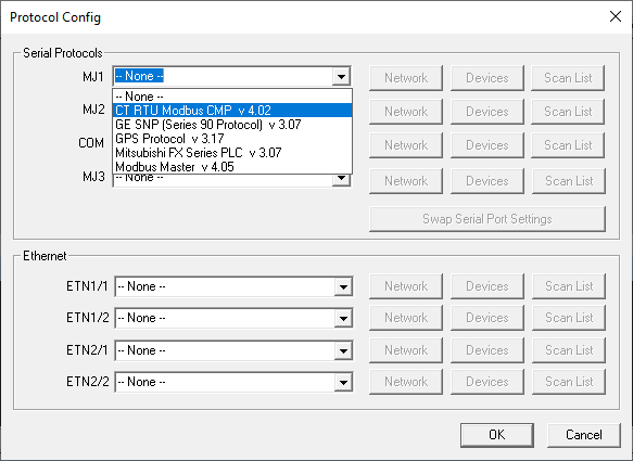
From the Cscape Home > Protocols menu, select the port drop-down box to select a protocol device driver. All protocol device drivers currently loaded in Cscape are displayed in the drop down selection along with their version numbers. A selected protocol can be removed by selecting None from the drop-down selection. Some OCS models can be limited in the number of ports or number of protocol device drivers that can be selected. Once a protocol is selected, the Network, Devices and Data (Scan List) must be configured through corresponding dialogs accessible through the respective buttons (Network, Devices and Scan List).
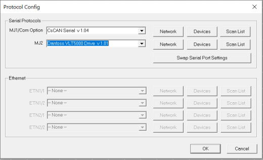
Swapping Serial Port Settings
Use Swap Serial Port Settings button to swap the protocol settings of 2 ports on the system. After execution of swapping, all the setting of respective protocol in Network, Device & Scan List get swapped. NOTE: Swapping with an unallocated port is equivalent to moving the settings from one port to another. The settings are retained automatically.
Swap between MJ1 & MJ2
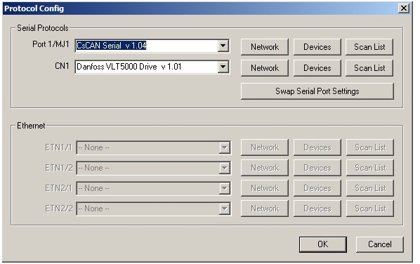
Swap between MJ1 & CN1
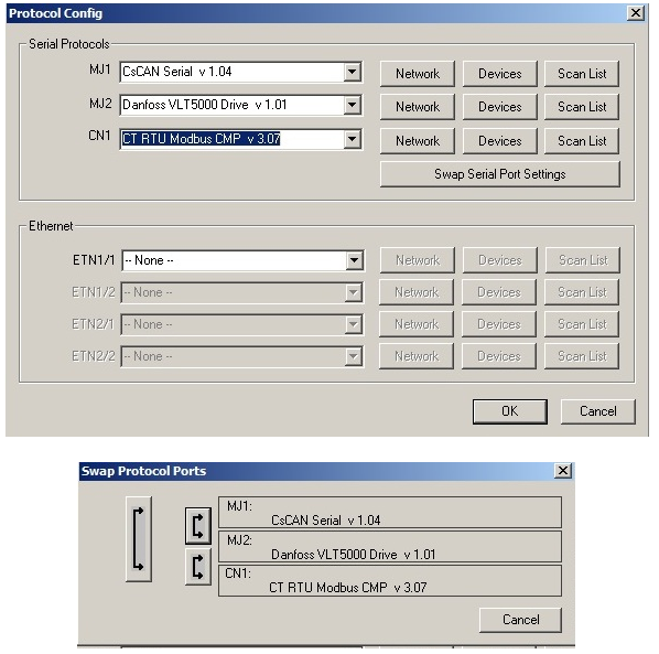
If more than 2 ports are available then the two may be selected in the Swap Protocol Ports dialog as shown below.
Swap between MJ1, MJ2 & CN1
Return to the Top: Protocol Configuration
Network Configuration
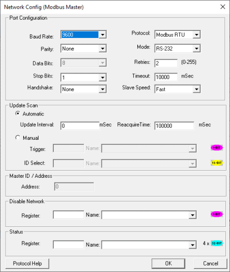
Port Configuration - This configuration dialog is reached from the Network button on the Protocol Config screen and provides the required parameters to configure the network. Each protocol is different and may not require all the Network Config fields. Baud Rate, Data bits, Stop bits, Parity - These fields define the bit level transfer over the serial port
-
None – No handshake lines are used
-
Multidrop Full – Rx remains active while Tx is occurring
-
Multidrop Half – Rx is shut off while Tx is occurring
-
Radio Modem – Wait for CTS acknowledgment before transmitting (legacy radio modem support)
Protocol - If a driver supports multiple protocols, it is selected here (i.e.: Modbus supports either RTU![]() RTU - Remote Terminal Unit - A microprocessor-based device that monitors and controls field devices, that then connects to plant control or SCADA (supervisory control and data acquisition) systems. or ANSI).
RTU - Remote Terminal Unit - A microprocessor-based device that monitors and controls field devices, that then connects to plant control or SCADA (supervisory control and data acquisition) systems. or ANSI).
Mode - Specifies if port operates in RS232 or RS485 mode.
Retries - Specifies number of times a transaction is retried on a failed response.
Timeout - Specifies the amount of time for a device to wait for a valid response.
Update Scan
-
Automatic
-
Update Interval - Specifies the update interval at which all the mapped entries are executed. To reduce network loading, decrease the update interval. One of the network status error count registers indicates when the actual transaction scan time takes longer than the update interval.
-
Reacquire Time - Specifies the amount of time to wait before attempting communications with an offline device. This feature can be disabled for individual device(s) through the device configuration menu.
-
-
Manual
-
Trigger (register) - Specifies the binary register that enables a single transaction scan of the Scan List. The OCS automatically resets this register when the transaction scan is complete.
-
ID Select (register) [optional] - If an analog register is specified in the field, the ID Select filter is enabled. When a manual transaction scan is initiated from the trigger register, only the Scan List entries with the specified device ID are enabled. NOTE: Certain IDs in this field can alter operation for specific protocols (i.e. Modbus call-on-exception).
-
Master I/D Address
From Cscape 9.90 SP3 and firmware 15.40 onwards, disable network feature has been added in protocol network configuration. This option is used to close the port and disable the protocol configured in that particular port. Single Bit register has to be configured to use this function. Setting the bit high closes the port and disables the protocol. OCS will not send any serial (TCP for Ethernet protocols) packets from this port until the bit is high. Setting the bit low will reopen the port and enables the protocol again. Status Register (see Network Status) - Specifies the starting OCS register of 8 consecutive registers (4-32bit counters), which provide an indication of the network health.
Specifies the OCS ’s device (network) ID if a master ID is required by the protocol.
Return to the Top: Protocol Configuration
Device List
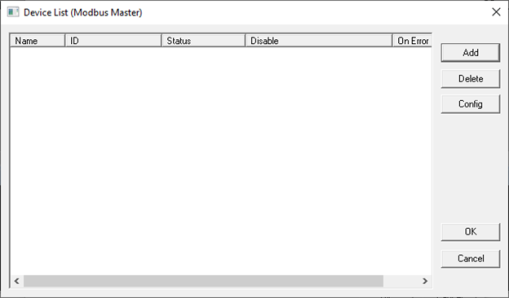
This configuration list is reached from the Device button on the Protocol Config screen and provides a list of the configured devices on the Network. Devices must be created and exist in this list before corresponding Scan List entries can be created for this device. Typically, the number of entries is limited to 128 devices.
-
Add - Opens the Device Config dialog to add a new device to the list.
-
Delete - Remove selected device from list (all corresponding Scan List entries are also removed).
-
Config - Invoke the Device Config dialog for the currently selected device. This can also be accomplished by double-clicking a device entry.
-
Mapping - Invoke the Scan List limiting the entries displayed for the selected device.
Device Configuration
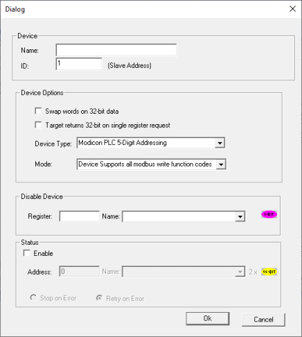
This configuration is reached from the device list when adding or modifying an existing device. While each protocol is somewhat different and can contain protocol specific field, all protocols typically support at least:
-
Device Name : Specifies a tag name for this device. This tag name is used in the Data Mapping configuration to identify this device. This allows device addresses to be modified without the need to update all associated Data Mapping entries.
-
Device ID : Specifies the target device communications ID or station address.
-
Swap Words on 32-bit Data: If a Scan List
A list of communications to carry out to one or more devices. Normally, the Master or Client device will execute this scan list, which is directed at Slave or Server devices. Scan List items may be Polled or Triggered. entry is configured to transfer 32-bits and this option is checked, the high and low 16-bit values are swapped when transferred between the target and OCS. -
Disable Device : From Cscape 9.90 SP3 and firmware 15.40 onwards, disable device feature has been added in protocol device configuration. This option is used to disable a particular slave configured in the network. Single bit register has to be configured to use this function. Setting the bit high disables the slave and OCS will not send any serial (TCP for ethernet protocols) packets only to this slave until the bit is high. Setting the bit low enables the communication with the slave again.
-
Status Enable: This checkbox enables device status to be displayed and controlled from two consecutive 16-bit registers.
-
Status Address
-
Enter the starting 16-bit OCS register of two consecutive registers used for device status. The first register contains the protocol device driver specific error code while the second register contains the index of the offending Scan List entry.
-
Status Modes
-
Stop on Error - Specifies that communications be only reattempted after offline status when the corresponding device status register is cleared.
-
Retry on Error - Specifies that communications be reattempted either during the reacquire interval or when the corresponding device status register is cleared.
-
Return to the Top: Protocol Configuration
Scan List
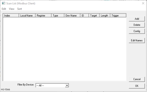
This configuration list is reached from the Scan List![]() A list of communications to carry out to one or more devices. Normally, the Master or Client device will execute this scan list, which is directed at Slave or Server devices. Scan List items may be Polled or Triggered. button on the Protocol Config screen or the Mapping button on the Device List screen and provides a Scan List of the Data Mapping entries. To transfer data between the OCS and remote target, a Scan List must be created that defines each transaction. Each mapping entry (transaction) contains the source and destination registers, the number of consecutive registers transferred, the direction of the transfer and what triggers the transfer. Typically, the number of entries is limited to 512.
A list of communications to carry out to one or more devices. Normally, the Master or Client device will execute this scan list, which is directed at Slave or Server devices. Scan List items may be Polled or Triggered. button on the Protocol Config screen or the Mapping button on the Device List screen and provides a Scan List of the Data Mapping entries. To transfer data between the OCS and remote target, a Scan List must be created that defines each transaction. Each mapping entry (transaction) contains the source and destination registers, the number of consecutive registers transferred, the direction of the transfer and what triggers the transfer. Typically, the number of entries is limited to 512.
Note: The order of the Scan List is the order in which the transactions occur. Sort functions are provided to change the order of the list. Each entry also has an identifying index. If the device status register is enabled and a transaction failure occurs, the status register indicates the index number of the transaction that failed.
Menu
Edit > Copy All - Copies Scan List to clipboard in a tab delimited format suitable for pasting into an application like Microsoft Excel.
Edit > Paste - Loads Scan List from clipboard. Pasted items are added to the scan list even if they are duplicates.
View > Toggle All Name View - Expands Scan List such that each point and corresponding local name is displayed.
Sort Scan List![]() A list of communications to carry out to one or more devices. Normally, the Master or Client device will execute this scan list, which is directed at Slave or Server devices. Scan List items may be Polled or Triggered. by different criteria. The firmware will scan the devices based on the order they are displayed or sorted. There are four ways to sort the scan list:
A list of communications to carry out to one or more devices. Normally, the Master or Client device will execute this scan list, which is directed at Slave or Server devices. Scan List items may be Polled or Triggered. by different criteria. The firmware will scan the devices based on the order they are displayed or sorted. There are four ways to sort the scan list:
-
By Local Address – Sorts the list by local register address in increasing order.
-
By Target Address – Sorts the list by target register address in increasing order.
-
By Device Name – Sorts by device name, then target address.
-
Interleave Devices – This sort evenly distributes request among the different devices. Instead of requesting 100 blocks from device A, then 100 blocks from device B, one requests is sent to device A, then one request is sent to device B until all the data has been requested. This is useful for devices that may have a timeout timer because the time between each scan for a particular device is minimized. This sorting options usually doesn’t affect performance.
Buttons
Add - Opens the Data Mapping dialog to add a new entry to the Scan List.
Delete - Removes selected entry from Scan List
Config - Opens the Data Mapping dialog for the currently selected entry. This can also be accomplished by double-clicking an entry.
Edit Names - Invokes the Edit Names dialog for the currently selected entry. The Edit Names dialog provides the ability to create OCS program names for each point in the transaction.
Display Control
Filter by Device - Limits displayed entries to only those assigned to the indicated device. To show all entries select –All--.
Data Mapping Configuration (Scan List Entry)
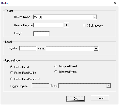
Device Name - Selects the target device (by tag name) to use for this transaction. Only those device entries previously created from the Device Config menu are available.
Device Register - Specifies the target device’s register to use for this transaction. This designation is target-specific. The configuration menu displays an error if a specified address is unacceptable. Generally, the data type of the local (OCS ) register must match the data type of the device register.
The Right Arrow button - Displays protocol device driver specific help for the target addressing. Note that some devices can require register addresses that exist on 8-bit, 16-bit or 32-bit boundaries.
Local Register - Specifies the local (OCS ) register that is the source or destination for the transaction.
Local Name [Optional] - Optionally allows selection of a OCS register by name <or> creation of a name for a register already selected by direct reference. Created names can be used thereafter to specify the local (OCS ) register in ladder or graphics address fields.
32-Bit Access - Allows two local (OCS ) 16-bit registers to be treated as a single 32-bit value. For example, if the value in either 16-bit register is modified, both registers are written to the device. Device-specific, 32-bit word swapping options also apply to this designation. Since the transaction is treated as a 32-bit access, the length is generally limited to 16. Note that some protocols can disable this feature.
Length
-
Specifies the number of consecutive device registers that are transferred in this transaction. Note that some protocols can limit the length that can be transferred. However, typically the length is limited to 32. The configuration menu displays an error if a specified length is unacceptable.
-
If allowed, specifying a length greater than one (multiple consecutive register transfers per transaction) is more efficient than creating a single transaction for each register. This grouping of registers per transaction can significantly reduce the transaction scan time; however, update types that include writing on a polled basis require additional consideration.
-
On Read/Write and Read/Write/Init update types, the write transaction only occurs when the local (OCS ) register value changes. If the length is greater than 1 for Read/Write and Read/Write/Init types, only the local register(s) that change in value are written. More specifically, only one write transaction occurs per scan per mapping entry for the register or consecutive sub-group of local registers that changed in value. Depending on the protocol, the number of points written with that write transaction are limited either to one or the number of consecutive points that changed value.
-
Therefore, if several local registers (specified in a single mapping entry) change in value prior to a transaction scan, it takes SEVERAL transaction scans to complete all the write operations. Furthermore, all write operations are completed before a read operation is scheduled.
-
For Manual Update (transaction) scans (i.e. dialup modem), it is recommended that all Read/Write Scan List entry lengths be limited to 1.
-
Update Type: This field specifies the direction and what triggers the transfer of data between the OCS and target device for a mapping entry.
-
Polled
Polled - When a device is consistently asked for data, either as fast as possible or on a time basis. Normally associated with Modbus communications. Read - On every transaction scan, a read-only target device register(s) transaction occurs.
-
-
On every transaction scan, a read target device register transaction occurs unless a local register value has changed. The write transaction only updates those local registers that have changed in value. If several non-consecutive local registers (contained in a single mapping entry) change value between transaction scans, it takes several consecutive transaction scans to write each changed register.
-
When the OCS is placed in RUN mode, the initial action for this mapping type is a read target register transaction. This transaction initializes the local (OCS ) register(s) to match that of the remote device register(s). Thereafter, any change to the corresponding OCS register(s) triggers a write operation to the remote device.
-
-
Polled Read/Write/Init
-
On every transaction scan, a read target device register transaction occurs unless a local register value has changed. The write transaction only updates those local registers that have changed in value. If several non-consecutive local registers (contained in a single mapping entry) change value between transaction scans, it takes several consecutive scans to write each changed register.
-
When the OCS is placed in RUN mode, the initial action for this mapping type is a write target register transaction. This transaction initializes the target device register(s) to match that of the local (OCS ) register(s). Thereafter, any change to the corresponding OCS register(s) triggers a write operation to the remote device.
-
The initial write transaction does not occur until after the first logic scan of the OCS . This allows registers to be initialized locally before Writing to the target device register(s).
-
-
Triggered Read - A read transaction is triggered by a high level on a separately designated OCS (binary) trigger register. Once the read transaction is complete (or the device is offline), the OCS trigger register is cleared by the OCS . This update type can be used for occasion data accesses such as retrieving trend data. Note that this operation increases the associated transaction scan time and can cause the Update Interval Exceeded Counter to increment on a tightly adjusted update interval.
-
Triggered Write - A write transaction is triggered by a high level on a separately designated OCS (binary) trigger register. Once the write transaction is complete (or the device is offline) the OCS trigger register is cleared by OCS . This function can be used for occasion data accesses such as sending recipe data. Note that this operation increases the associated transaction scan time and can cause the Update Interval Time Exceeded Counter to increment on a tightly adjusted update interval.
For the Downlodable Protocol DLLs and Help files, please see the following links:
North America: https://hornerautomation.com/support-files/#
Europe : https://www.hornerautomation.eu/support/protocols/
Return to the Top: Protocol Configuration
External Registers
To view data on the screen from an external device connected using configurable protocols, it is required to map the data into OCS registers and then display the data on the screen.
With Cscape 9, the external registers (registers of the device connected to OCS through serial / Ethernet protocols) can be directly accessed from the graphics objects. This provides three major benefits.
-
Easy of programming
-
Reduced register usage
-
Data transferred only when required
Accessing External Registers
Step 1: Configure the protocol for communication with the external device. See Protocol Configuration for details. Before accessing registers of external device in graphics objects, Network Configuration and Device Configuration needs to be complete. NOTE: The scan list![]() A list of communications to carry out to one or more devices. Normally, the Master or Client device will execute this scan list, which is directed at Slave or Server devices. Scan List items may be Polled or Triggered. configuration is not required if the user wants to only access the data of external device from the OCS screens.
A list of communications to carry out to one or more devices. Normally, the Master or Client device will execute this scan list, which is directed at Slave or Server devices. Scan List items may be Polled or Triggered. configuration is not required if the user wants to only access the data of external device from the OCS screens.
Step 2: Place the graphics object for displaying the data and double click to configure its properties. The following dialog will be displayed.
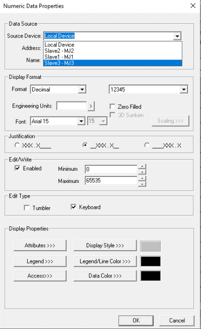
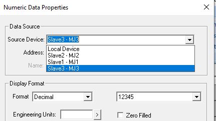
Step 3: Select the required protocol from the Data Source dropdown. Cscape will show all the configured protocols here.
Step 4: Enter the parameter address of the external device. The right arrow button can be clicked to get help on the accessible parameters.
Step 5: Select the register width for the configured external parameter. When the OCS switches to the screen having objects with external registers in RUN mode, the data is polled![]() Polled - When a device is consistently asked for data, either as fast as possible or on a time basis. Normally associated with Modbus communications. from the external device and displayed on the screen.
Polled - When a device is consistently asked for data, either as fast as possible or on a time basis. Normally associated with Modbus communications. from the external device and displayed on the screen.
Note:
-
On disconnection of Slave & master, the data field in Master should show *** & reconnection should recover back the data from firmware 12.80 and Cscape 9.2 onwards.
-
From Cscape 9.30 SP4 onwards, the display of asterisk on no communication / disconnection of Slave and Master has been made configurable from Graphics Editor.
In the Graphics Editor, select Tools > Edit Options, and the following window is displayed:
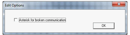
If the option Asterisk for broken communication is selected, the data field in Master displays asterisk *** on disconnection of Slave and Master.
If the option Asterisk for broken communication is not selected, then the data field in Master retains the previous value that has been displayed.
Return to the Top: Protocol Configuration