2.5G Modem / 3G Modem Configuration
See also: Networking and Communications
Topic Menu
Modem Overview

|
Using a 5G Cellular Modem with Horner OCS |
GSM modem module supports the following features:
-
GPRS Data –Supports CScape, Envision connection, communication between devices and Data exchanges
-
SMS – Supports SMS using Modem
-
Email – Supports Email through GPRS.
Add Modem to Hardware Configuration
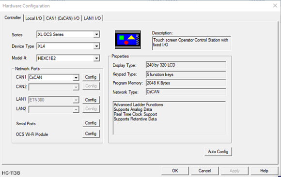
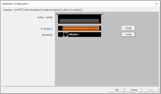
To Add modem Hardware in Cscape configuration, select Hardware Configuration > Local I/O
On selecting Hardware Configuration, the following window pops up:
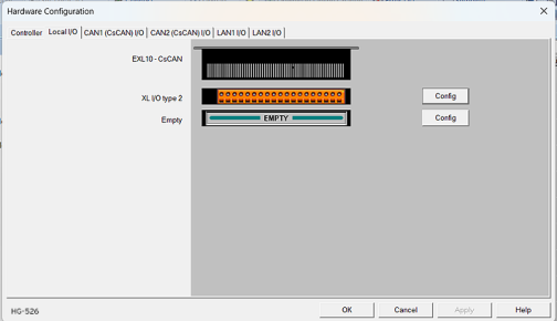
Select Local I/O tab and select Config next to the "Empty" image.
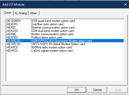
User can select HE-XRC2Q or HE-XRC3D modem depending on their requirement.
Select OK and the following will appear:
Return to the Top: 2.5G Modem / 3G Modem Configuration
Mobile Data Configuration
Step 1a: To configure modem, select Messaging > Mobile Data Network. NOTE: Ensure that a modem has been selected per the previous step.
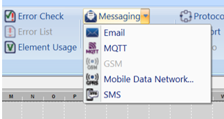
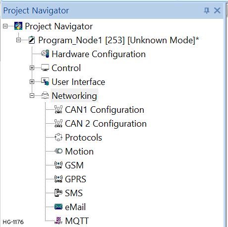
Step 1b: Mobile Data Network can also be accessed from the Project Navigator.
Step 2: On selecting Mobile Data Network, the following window will pop up:
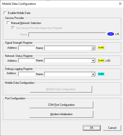
Step 3a: Enable Mobile Data
When this option is checked the Modem gets connected to the service provider automatically. Mobile data is used to send GPRS data and Email through GPRS.
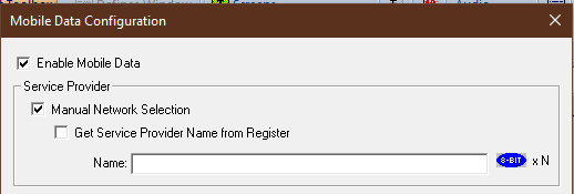
Step 3b: Manual Network Selection
In case selection of service provider needs to be done manually, Manual Network selection can be checked. The network provider name can be directly given in Name field or the same can be provided through a register / Variable reference as well. To provide register/variable reference for service Provider, check Get Service Provider Name from Register and enter the register/variable reference in Address. In this case, the preferred service provider name string with null termination![]() Null Termination - To place a NULL character (character code 0) at the end of ASCII data. Some functions require NULL Termination to be able to determine the end point of the ASCII data since that data may vary in length from one time to the next. needs to be provided at the specified register / Variable.
Null Termination - To place a NULL character (character code 0) at the end of ASCII data. Some functions require NULL Termination to be able to determine the end point of the ASCII data since that data may vary in length from one time to the next. needs to be provided at the specified register / Variable.
Step 4: Signal Strength Register
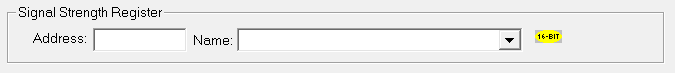
Configure a register address to store Signal strength. The signal strength values and description are as follows:
|
Register Value (Decimal) |
Signal Strength |
Description |
|
99 |
|
Not Known or Not detectable |
|
0 |
-113 or less |
Marginal |
|
1 |
-111 |
Marginal |
|
2 |
-109 |
Marginal |
|
3 |
-107 |
Marginal |
|
4 |
-105 |
Marginal |
|
5 |
-103 |
Marginal |
|
6 |
-101 |
Marginal |
|
7 |
-99 |
Marginal |
|
8 |
-97 |
Marginal |
|
9 |
-95 |
Marginal |
|
10 |
-93 |
OK |
|
11 |
-91 |
OK |
|
12 |
-89 |
OK |
|
13 |
-87 |
OK |
|
14 |
-85 |
OK |
|
15 |
-83 |
Good |
|
16 |
-81 |
Good |
|
17 |
-79 |
Good |
|
18 |
-77 |
Good |
|
19 |
-75 |
Good |
|
20 |
-73 |
Excellent |
|
21 |
-71 |
Excellent |
|
22 |
-69 |
Excellent |
|
23 |
-67 |
Excellent |
|
24 |
-65 |
Excellent |
|
25 |
-63 |
Excellent |
|
26 |
-61 |
Excellent |
|
27 |
-59 |
Excellent |
|
28 |
-57 |
Excellent |
|
29 |
-55 |
Excellent |
|
30 |
-53 |
Excellent |
|
31 |
-51 dBm or greater |
Excellent |
Step 5: Network Status Register
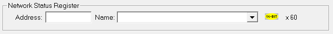
Network Status Register uses block of 60 consecutive register to indicate the status of the Network. The details of status registers for 2.5G/ 3G modems are as follows: Network status register+0: 16bits
|
Bit 1 |
TRUE if basic modem initialization is done |
|
Bit 2 |
TRUE if context activation for data connection is done |
|
Bit 3 |
Reserved |
|
Bit 4 |
TRUE if Manual registration is done |
|
Bit 5 |
TRUE if Modem initialization is going on |
|
Bit 6-8 |
Unused |
|
Bit 9 |
TRUE if Modem communication is not working |
|
Bit 10 |
TRUE SIM PIN command fails |
|
Bit 11 |
TRUE if registration failed |
|
Bit 12 |
Reserved |
|
Bit 13 |
Unused |
|
Bit 14 |
Unused |
|
Bit 15 |
Reserved |
|
Bit 16 |
Unused |
| Network status register + 1 |
32bit |
Network allocated IPV4 in binary |
| Network status register + 3 |
16 Bytes |
IMEI Number of Modem |
| Network status register + 11 |
16 Bytes |
Reserved |
| Network status register + 19 |
16 Bytes |
Reserved |
| Network status register + 27 |
2 Bytes |
Modem initialization count |
| Network status register + 28 |
2 Bytes |
Modem initialization success count |
| Network status register + 29 |
2 Bytes |
Modem context activation success count |
| Network status register + 30 |
(80 x 6) Bits |
Individual Socket status (6 registers currently 3 in use) Socket 1 - Modem Block Socket 2 - Cscape Socket 3 - Email Socket 4 to 6 - Reserved |
Network status register + 30: (80 x 6) Bits
|
Bit 1 |
Connection_type | TCP-0 or UDP-1 |
|
Bit 2 |
Connection_dial | TRUE if socket is dial, else Listen |
|
Bit 3 |
Connection_open | TRUE if open, 0 for close |
|
Bit 4 |
Conn_lsn_err | TRUE if Listen mode or connecting to client fails |
|
Bit 5 |
Conn_acpt_err | TRUE if accepting connection fails |
|
Bit 6 |
Conn_send_err | TRUE if data send fails |
|
Bit 7 |
Conn_recv_err | TRUE if data receive fails |
|
Bit 8 |
Sock_buf_over | Buffer overflow error |
|
Bit 9 to 16 |
Connection_status |
Contains different modem status 0 - Socket is Free 1 - Socket is requested 2 - Socket connection is establishing. 3 - Socket is closed. 4 - Socket is listening. 5 - Socket with an incoming connection request. 6 - Socket with an active data transfer connection. 7 - Socket is suspended 8 - Socket is suspended with pending data |
|
Bits 17 to 48 |
Total data sent (In bytes) | |
|
Bits 49 to 80 |
Total data received (In bytes) |
Debug Logging Register – This Register/Variable is used to enable debug log and log file will be created in microSD card .THIS REGISTER MUST BE TURNED ON ONLY IF THERE ARE ANY ISSUES WITH MODEM FUNCTIONALITIES. For normal operations the register/variable value must be turned OFF. NOTE: Turning ON Debug Logging register/variable will have an impact on scan rate.
Return to the Top: 2.5G Modem / 3G Modem Configuration
SMS COM Port Configuration
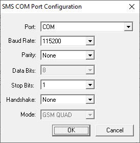
In the Mobile Data configuration dialog, selecting SMS COM Port Configuration pops up the following window:
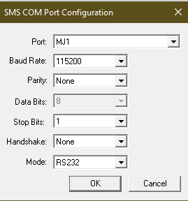
The following selections must match the default settings of the modem that is being used:
Port - Select the desired port. The number of ports vary depending on the controller used
Mode - Select connection mode. The drop-down list changes according to the port selection
Comm Settings - Select Baud Rate,
Parity, Data Bits, Stop Bits and Handshake![]() Handshaking is an automated process that sets parameters for communication between two different devices before normal communication begins. Much like the way a human handshake sets the stage for the communication to follow, the computing handshake provides both devices with the basic rules for the way data is to be shared between them. These rules can include transfer rate, coding alphabet, parity, and interrupt procedure. settings as per the default
settings of the modem that is being used.
Handshaking is an automated process that sets parameters for communication between two different devices before normal communication begins. Much like the way a human handshake sets the stage for the communication to follow, the computing handshake provides both devices with the basic rules for the way data is to be shared between them. These rules can include transfer rate, coding alphabet, parity, and interrupt procedure. settings as per the default
settings of the modem that is being used.
Port configuration for HE-XRC2Q (2.5G) and HE-XRC3D (3G) Modems should be as below:
NOTE: Select Port as COM or MJ1/COM based on controller type. In XLE/XLT/XLEe/XLTe controllers HE-XRC3D/HE-XRC2Q modem utilizes the same internal communications channel (UART) as the MJ1 serial port; thus, enabling the modem deactivates the MJ1 serial port. However, support is provided to select which device (or port) is currently active. XL4, EXL6, EXLW, XL7 & EXL10 provide a COM port to support the modem thereby leaving MJ1 free for other use.
Return to the Top: 2.5G Modem / 3G Modem Configuration
Modem Initialization
Selecting Modem Initialization pops up the following window:
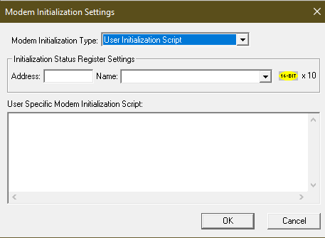
Configuration of Initialization Status Register Settings and User Specific Modem Initialization Script in the above screen is required when User Initialization Script is selected
|
Modem Initialization Type |
The following options are available:
The type of Modem Initialization used affects various settings that are available on the COM Port screen. |
|
Address |
Enter the starting register address location used to store the additional modem initialization script’s latest command executed. This is a block of 10 registers that are consecutive in memory. For example, if the users are using R301 - R310, then the users need to enter the starting register address as %R301. |
|
Name |
Enter (or select) the I/O Name. |
|
User Specific Modem Initialization Script |
Enter script in this box. |
Return to the Top: 2.5G Modem / 3G Modem Configuration