SmartStix and SmartBlock Modules
See also: General I/O Configuration
Topic Menu

|
Remote I/O Configuration |

|
Energy Monitoring Application: Cscape Example |
SmartStix and SmartBlock Configuration
All OCS Controllers with CsCAN![]() Horner APG's proprietary network protocol that runs on the Bosch CAN network specifications. Prior to the advent of the OCS. ports support SmartStix configuration. The following dialog will appear on pressing Add button in CsCAN I/O.
Horner APG's proprietary network protocol that runs on the Bosch CAN network specifications. Prior to the advent of the OCS. ports support SmartStix configuration. The following dialog will appear on pressing Add button in CsCAN I/O.
Note: Configuration of SmartBlock is the same as SmartStix.
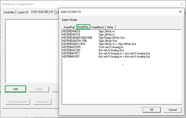
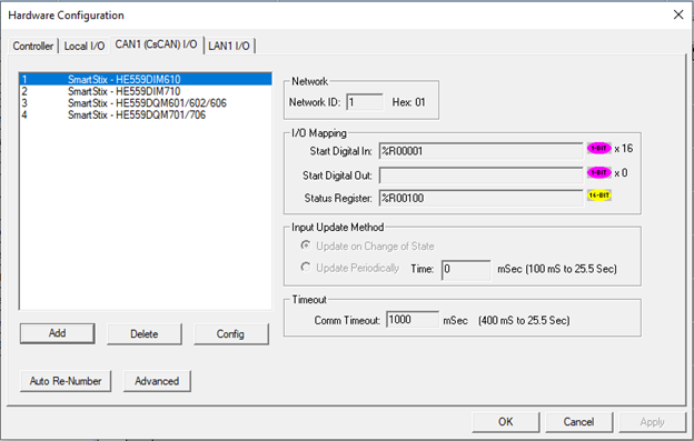
The CsCAN I/O configuration allows up to 99 SmartStix™ remote CsCAN I/O devices to be easily configured and assigned to controller registers. The dialog above is used to manage the list of networked CsCAN I/Os. The list shows the network ID & a brief description of the module. This list is always sorted by network ID. There are several buttons used to manage this list of devices:
-
Add: This allows adding a CsCAN I/O to the list. The user will be prompted to choose a CsCAN I/O. The <INS> key can also be used to add a device.
-
Delete: This deletes the currently selected CsCAN I/O. Pressing the <DEL> key on the keyboard is equivalent.
-
Config: This will configure (edit) the currently selected IO module. This can also be accomplished by pressing the <ENTER> key or double-clicking a device in the list.
-
Auto Re-Number: This allows the registers to be assigned a new starting point and force a consecutive block of registers.
-
Advanced: This allows setting advanced options such as support for extended time-outs on digital modules.
Digital SmartStix Modules
Selecting any Digital SmartStix module from the Smart Stix tab brings up the following window:
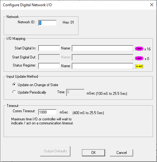
Network ID![]() Usually refers to the ID of the device on a supported CAN, such as CsCAN, CANopen, etc. Each device must have a unique network ID. Also called Node ID.: This sets the network ID assigned to the SmartStix module. This must be a constant. Valid address range is from 1 to 253
Usually refers to the ID of the device on a supported CAN, such as CsCAN, CANopen, etc. Each device must have a unique network ID. Also called Node ID.: This sets the network ID assigned to the SmartStix module. This must be a constant. Valid address range is from 1 to 253
I/O Mapping: This sets the starting registers for inputs, outputs and the status registers. Not all modules have both inputs and outputs. The indicator next to the register entry always shows the number of registers used. One 16-bit status registers is always required. There are few restrictions on what registers can be assigned. System bits (%S![]() Single-bit bit coils predefined for system use.) and system registers (%SR
Single-bit bit coils predefined for system use.) and system registers (%SR![]() 16-bit registers predefined for system use.) cannot be used for inputs, outputs, or status registers.
16-bit registers predefined for system use.) cannot be used for inputs, outputs, or status registers.
Input Update Method: An I/O Module with digital inputs can be configured to update its digital input data either on change of state or periodically. The update period is programmable from 10 mS to 255 Seconds.
Timeout - This setting determines how long the controller or SmartStix wait to determine if there is a communication error. If communications between the I/O and controller have stopped for the timeout entered, the SmartStix will set all its outputs to default and indicate a lifetime error. The controller will set the off-line status bit and attempt to re-configure the module. The SmartStix and controller will be programmed to exchange heartbeat CsCAN network message at twice the rate indicated by this timeout. When a controller is placed in IDLE mode, it stops communicating with the CsCAN I/O and this timeout will control how long it takes for the I/O to go to its default state.
Return to the Top: SmartStix and SmartBlock Modules
Digital Output Module
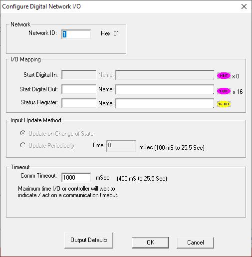
Output Defaults: Pressing this button brings up below dialog to set the default state for the outputs when communication between host controller and Smart Stix is lost or host controller went to Idle mode.
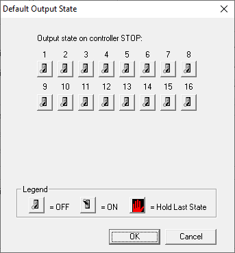
OFF: Outputs are Turned OFF
ON: Outputs are Turned ON
Hold Last State: Outputs are Hold at last state
Note: Number of outputs depend on Module selected.
After configuring the modules, select OK to add the SmartStix modules to the CsCAN I/O list as shown below:
The right side of the window displays the configuration of the selected module in the list.
Return to the Top: SmartStix and SmartBlock Modules
Analog SmartStix Modules
Selecting any Analog SmartStix module from the SmartStix tab bring up the following window:
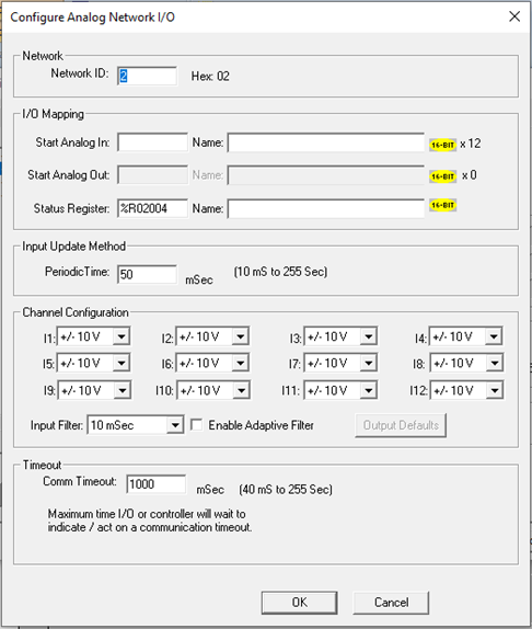
Network ID![]() Usually refers to the ID of the device on a supported CAN, such as CsCAN, CANopen, etc. Each device must have a unique network ID. Also called Node ID.: This sets the network ID assigned to the SmartStix module. This must be a constant. Valid address range is from 1 to 253
Usually refers to the ID of the device on a supported CAN, such as CsCAN, CANopen, etc. Each device must have a unique network ID. Also called Node ID.: This sets the network ID assigned to the SmartStix module. This must be a constant. Valid address range is from 1 to 253
I/O Mapping: This sets the starting registers for inputs, outputs, and the status registers. Not all modules have both inputs and outputs. The indicator next to the register entry always shows the number of registers used. One 16-bit status registers is always required. There are few restrictions on what registers can be assigned. System bits (%S![]() Single-bit bit coils predefined for system use.) and system registers (%SR
Single-bit bit coils predefined for system use.) and system registers (%SR![]() 16-bit registers predefined for system use.) cannot be used for inputs, outputs, or status registers.
16-bit registers predefined for system use.) cannot be used for inputs, outputs, or status registers.
Input Update Method: An I/O Module with analog inputs always updates its analog input data periodically. The update period is programmable from 10mS to 255 seconds.
Channel Configuration: This section of the dialog is used to setup the inputs and outputs for the module.
Timeout: This setting determines how long the controller or SmartStix wait to determine if there is a communication error. If communications between the I/O and controller have stopped for the timeout entered, the SmartStix will set all its outputs to default and indicate a lifetime error. The controller will set the off-line status bit and attempt to re-configure the module. The SmartStix and controller will be programmed to exchange heartbeat network message at twice the rate indicated by this timeout. When a controller is placed in IDLE mode, it stops communicating with the CsCAN I/O and this timeout will control how long it takes for the I/O to go to its default state.
Return to the Top: SmartStix and SmartBlock Modules
Analog Output Module
Output Defaults – Pressing this button brings up the below dialog to set the default values for the outputs when communication between the host controller and SmartStix is lost or if the host controller went into Idle mode.
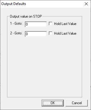
Hold Last Value
-
Checked: Analog output values are Hold at last value
-
Unchecked: Ana analog output will be forced to value entered in Goto field.
After configuring the modules, select OK in the Configure Analog Network I/O dialog. Cscape will add the SmartStix modules to the CsCAN I/O list as shown below:
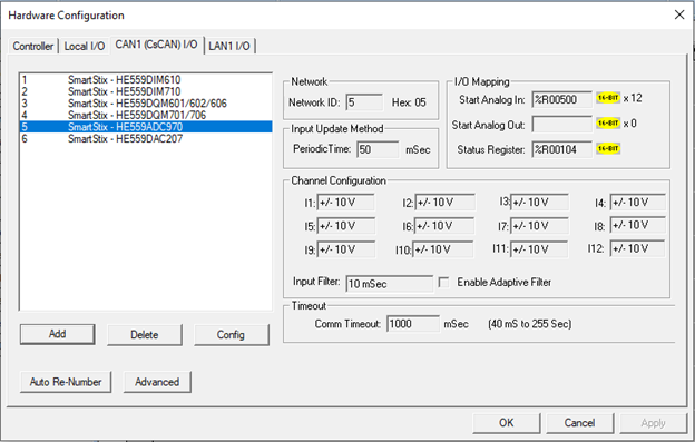
The right side of the window displays the configuration of the selected module in the list.
Return to the Top: SmartStix and SmartBlock Modules
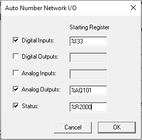
Auto Re-Numbering Feature
The auto re-number feature allows one or more types of register assignments to be re-numbered at a specified starting point.
-
Select one or more types of register assignments to change by clicking the check box to the left.
-
Enter the starting register for each type selected.
-
Press OK. This will renumber the selected configuration data, starting at the smallest network ID.
Return to the Top: SmartStix and SmartBlock Modules
Operation of the CsCAN SmartStix I/O
Once the list of CsCAN SmartStix I/O has been configured it must be downloaded to the controller. The normal download process will accomplish this. Once the controller has the configuration and all the CsCAN SmartStix I/O devices are connected, the I/O is ready to use.
Note: If a SmartStix device is configured as CsCAN I/O the user program should not use networking function blocks (Net Put, Net Get, Put Heartbeat…) to communicate with the same module. These function blocks may be used to communicate with other devices that are not configured as CsCAN I/O.
When the controller is in IDLE mode, it will not exchange data with CsCAN SmartStix I/O. It will determine if the CsCAN I/O’s are on-line and start the configuration process. The status registers and CsCAN I/O OK (%S13) bit are updated even when controller is in idle mode. If a CsCAN SmartStix I/O device is brought on-line while controller is in idle mode, the status will reflect that the CsCAN I/O is on-line, but not configured. This is normal, the configuration process cannot be completed until the controller is in DO I/O mode or RUN mode.
Once the controller is in DO I/O mode or RUN mode, the configuration of the module is completed and data is transferred to and from the CsCAN SmartStix I/O. Once per scan, input data the module has transmitted on to the CsCAN network is copied into the controller registers assigned as inputs. When data assigned as outputs has changed, the controller will send updated data to the CsCAN SmartStix I/O. Outputs are also transmitted to the CsCAN SmartStix I/O immediately after the device is configured, after the controller detects a life time error, or if the SEND bit in the status is set.
If all the configured CsCAN I/O are on-line and no errors were found, the CsCAN SmartStix I/O OK (%S13) system bit is set. This bit turns off if any errors were found, a CsCAN I/O goes off-line, or if a CsCAN I/O is being re-configured. On a transition from IDLE to RUN mode it may take several scans before the CsCAN I/O OK bit is set while the devices complete configuration.
While running there are several checks going on to determine that all the CsCAN SmartStix I/O is functioning properly. The CsCAN SmartStix I/O and controller are constantly communicating. If communications are interrupted for a period determined by the timeout, the module is marked off-line in the status. The controller will continue to attempt communications and will re-configure the CsCAN I/O once it is back online. Data exchange with the CsCAN I/O will resume automatically.
If the CsCAN SmartStix I/O suffers from a brief power outage, it will lose its configuration. The controller can detect this event and will re-configure the CsCAN I/O and resume exchanging data. Communications from the controller to the CsCAN SmartStix I/O can be interrupted such that the I/O times out and sets the outputs to default. This is usually caused by faulty wiring or a saturated network. If this occurs, the controller notes the event by setting a bit in the status register and re-transmits the outputs to the CsCAN SmartStix I/O device.
Return to the Top: SmartStix and SmartBlock Modules
SmartStix Status Register Definition
| Bit 8 | Bit 7 | Bit 6 | Bit 5 | Bit 4 | Bit 3 | Bit 2 | Bit 1 |
|---|---|---|---|---|---|---|---|
| Version Error | Incorrect Module | Not Configured | Offline | ||||
| Bit 16 | Bit 15 | Bit 14 | Bit 13 | Bit 12 | Bit 11 | Bit 10 | Bit 9 |
| Send | Reconfig | Lifetime | |||||
All unassigned bits are reserved. The status is designed such that if the lower BYTE![]() Byte - [Data Type BYTE] - A string of 8 consecutive bits. A single BYTE is also the size of a single ASCII character. (bits 1 to 8) are all zero, the device is configured and running normally.
Byte - [Data Type BYTE] - A string of 8 consecutive bits. A single BYTE is also the size of a single ASCII character. (bits 1 to 8) are all zero, the device is configured and running normally.
Bits 9 and 10 are sticky bits. These bits are set by the firmware to indicate that the event occurred. The user program can optionally clear these bits by directly writing to them if it is logging or acting on these errors.
Offline:This bit turns on if the module is not detected on the CsCAN network.
Not Configured: This bit turns on if the module is in the process of being configured.
Incorrect Module: The detected module and the configured module do not match.
Version Error: The I/O Module firmware does not support the selected Advanced options (Extended timeouts for digital modules).
Lifetime Error: (Sticky bit) This bit is set if the SmartStix module detected a lifetime error. This error occurs if the controller stops communicating to the module.
Reconfig Error: (Sticky bit) This bit is set if the module had to be re-configured. This can happen if the module is power-cycled, or the controller stopped receiving communication from the module and detected a timeout error.
Send: Normally, all digital and analog outputs are updated only when their assigned Host Controller source registers change value. An application can set the Send bit TRUE to force all output data to be send. when all outputs have been updated, the Send bit is automatically set FALSE.
Return to the Top: SmartStix and SmartBlock Modules