The BACnet IP Server Protocol
BACnet is a data communication protocol for building automation and control networks.
Note: This protocol is supported in XL4e/XL7e/EXL10e/EXL6e/X5, ZX, RCC, XLPlus.
BACnet stack services supported
The BACnet stack currently implements the following services listed in the table. We plan to add the rest of the services as we go. With the services that are implemented, User can build a BACnet device that meets the standardized profile for a BACnet Smart Sensor, BACnet Smart Actuator, or a BACnet Application Specific Controller.
| BACnet Service | Initiate | Execute |
|---|---|---|
| Who Is | - | Yes |
| I Am | Yes | Yes |
| Who Has | Yes | Yes |
| I Have | Yes | Yes |
| Read Property | Yes | Yes |
| Write Property | Yes | Yes |
| Read Property Multiple | Yes | Yes |
| Write Property Multiple | - | Yes |
BACnet Object Supported
- Device
- Analog Value
- Analog Output
- Analog Input
- Digital Value
- Digital Input
- Digital Output
BACnet Server Address mapping for OCS and supported functions
Mandatory Parameters for the Device object
- Object Identifier - As per the BACnet specification 2 << 22 + index – e.g 0x02000010 for node Id 16.
- Object Name - Model Series name. e.g. XL4e
- Object Type - An enumerated type ‘device’ with value 8
- System Status - An enumerated value which can show the values 0, ‘operational’; 1, ‘operational read only’; 2, ‘download required’: 3, ‘download in progress’: 4, ‘non operational’: 5, ‘backup required’.
- Vendor Name - Horner APG LLC
- Vendor Identifier - The Vendor Identifier allocated to Horner, 600.
- Model Name - A string eg. “XC1E3” The Model Number of the product. i.e. XC1E3
- Firmware Revision - Firmware Version in the format "xx.yy". e.g. 12.96
- Application Software Revision - Internal firmware rev.
- Protocol Services Supported - A bit string with 40 bits (5 bytes) with bits set for I Am, I Have, Who Has, Who Is, readProperty, readPropertyMultiple, writeProperty, writePropertyMultiple, 0x00 0xD0, 0x01, 0x06, 0x03
- Protocol Object Types Supported - A bit string with 50 bits with bits set for Analog Value, Analog Input, Analog Output, Digital Value, Digital Input, Digital Output and Device.
- Object List - A BACnet array containing Analog Value, Analog Input, Analog Output and Device
- MAX APDU length supported - Unsigned; BACnet/IP 1476
- Segmentation supported - 3 – no segmentation
- APDU timeout - Unsigned – Defaults to 3000, can be changed.
- APDU retries - Unsigned – Hardcoded to 3.
- Device Address Binding - empty.
- Database Revision - 0
Mandatory Parameters for the Analog Value objects
- Object Identifier - Encoded as per the BACnet specification 2 << 22 + index – e.g. 0x00800064 for %R100
- Object Name - A string e.g. “%R100”
- Object Type - An enumerated type ‘analog-value’ enumerated value 2
- Present Value - The value in the %R Register encoded as a real number Real -32768.0 to -32767.0
- Status Flags - A bit string containing 4 zeros, Not used currently.
- EventState - An enumerated value indicating ‘normal’ – enumerated value 0
- OutOfService - A boolean – Always FALSE.
- Engineering Units - An enumerated value indicating ‘No Units’ - enumerated value 95.
- Description - A string eg. "Retentive Register of BACnet Server"
Mandatory Parameters for the Analog Input objects
- Object Identifier - e.g. %AI4
- Object Name - A string e.g. “%AI4”
- Object Type - An enumerated type ‘analog-input’ enumerated value 0
- Present Value - The value in the %AI Register encoded as a real number Real -32768.0 to -32767.0
- Status Flags - A bit string containing 4 zeros, Not used currently.
- EventState - An enumerated value indicating ‘normal’ – enumerated value 0
- OutOfService - A boolean – Always FALSE.
- Engineering Units - An enumerated value indicating ‘No Units’ - enumerated value 95.
- Description - A string eg. "%AI4"
Mandatory Parameters for the Analog Output objects
- Object Identifier - e.g. %AQ4
- Object Name - A string e.g. “%AQ4”
- Object Type - An enumerated type ‘analog-output’ enumerated value 1
- Present Value - The value in the %AQ Register encoded as a real number Real -32768.0 to -32767.0
- Status Flags - A bit string containing 4 zeros, Not used currently.
- EventState - An enumerated value indicating ‘normal’ – enumerated value 0
- OutOfService - A boolean – Always FALSE.
- Engineering Units - An enumerated value indicating ‘No Units’ - enumerated value 95.
- Description - A string eg. "%AQ4"
Mandatory Parameters for the Digital Value objects
- Object Identifier - e.g. Object_Binary_Value :100
- Object Name - A string e.g. “%M100”
- Object Type - An enumerated type ‘digital-value’ enumerated value 5
- Present Value - The value in the %M Register Boolean 0 or 1.
- Status Flags - A bit string containing 4 zeros, Not used currently.
- EventState - An enumerated value indicating ‘normal’ – enumerated value 0
- OutOfService - A boolean – Always FALSE.
- Description - A string eg. "%M100"
Mandatory Parameters for the Digital Input objects
- Object Identifier - e.g. Object_Binary_Input :100
- Object Name - A string e.g. “%I100”
- Object Type - An enumerated type ‘digital-input’ enumerated value 3
- Present Value - The value in the %I Register Boolean 0 or 1.
- Status Flags - A bit string containing 4 zeros, Not used currently.
- EventState - An enumerated value indicating ‘normal’ – enumerated value 0
- OutOfService - A boolean – Always FALSE.
- Description - A string eg. "%I100"
Mandatory Parameters for the Digital Output objects
- Object Identifier - e.g. Object_Binary_Output :100
- Object Name - A string e.g. “%Q100”
- Object Type - An enumerated type ‘digital-output’ enumerated value 4
- Present Value - The value in the %Q Register Boolean 0 or 1.
- Status Flags - A bit string containing 4 zeros, Not used currently.
- EventState - An enumerated value indicating ‘normal’ – enumerated value 0
- OutOfService - A boolean – Always FALSE.
- Description - A string eg. "%Q100"
Cscape Configuration
Following are the steps for configuring BACnet IP with Cscape application.
- Open Hardware configuration dialog and select XL4e/XL7e.
- Select Config button next to Ethernet slot and click Module Setup tab to configure IP address of the Master device.
- Open Program -> Protocol Config and perform the following configurations:
- Select BACnet IP protocol from the Ethernet drop-down list.
- Selecting Network tab opens the following window & in network configuration dialog user can configure following network parameters/ status registers.
- Configure minimum and maximum value for Port ID’s as 1024 and 2048 respectively.
- Configure the (optional) network status register.
- Click Devices button to configure ID and Port number.
- Click Scan List Button to configure the following.
- Select BACnet IP protocol from the Ethernet drop-down list.
The user can configure the required Data types and length in the above dialog box. The limitation for each data type is below:
- Analog Values – 5000
- Analog Input – 256
- Analog Output – 256
- Digital Values – 1000
- Digital Inputs – 256
- Digital Outputs – 256
Network Communication Errors
In order to access the Network statistics, user must assign the “Network status register” in network configuration. It occupies 8 consecutive registers. The table below gives the details of statistics.
| Number | Statistics | Location | Description |
|---|---|---|---|
| 1 |
Reserved |
%Rx | Reserved |
| 2 |
NoFrameCount |
%R(x+2) | This register explains number of times that a device(s) did not respond to a transaction. This includes ALL failed transaction, not just those after the retry count is exceeded. |
| 3 |
BadFrameCount |
%R(x+4) | This register explains number of times that a device(s) returned an invalid or failed response to a transaction. This includes ALL failed transaction, not just those after the retry count is exceeded |
| 4 |
GoodFrameCount |
%R(x+6) | This register explains total number of valid responses. |
Note: %Rx: 32-bit network status register configured in Network configuration. For example: %R500.
Connections
Media and Cabling
| Cable Specification | Shielded and non-shielded twisted-pair 10/100Base-T cables with RJ45 connectors |
| Maximum Length between two stations | 100 meters (323 feet) |
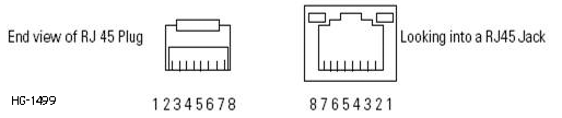
Ethernet Connections
The Ethernet connector, Channel 1, is an RJ45, 10/100Base-T connector. The pin-out for the connector is shown below:
| Pin | Pin Name |
|---|---|
|
1 |
Tx+ |
|
2 |
Tx- |
|
3 |
Rx+ |
|
4 |
not used by 10/100Base-T |
|
5 |
not used by 10/100Base-T |
|
6 |
Rx- |
|
7 |
not used by 10/100Base-T |
|
8 |
not used by 10/100Base-T |