Digital I/O
See also: General I/O Configuration
Topic Menu
Digital Input Configuration
Home > Hardware Configuration [select Device Type/Model#] > Local I/O Tab > I/O/Config Button > Module Setup > Digital In/HSC
Select Hardware Configuration from the Home menu and ensure that the correct Device Type and Model# are selected. Then select the Local I/O tab.
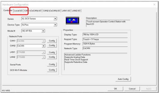
After selecting Local I/O, select the Config button next to the I/O connector.
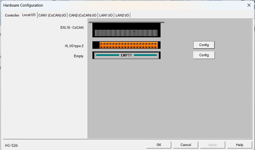
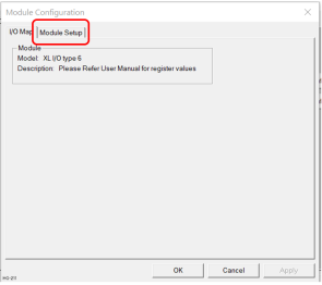
The Module Configuration screen will appear, select the Module Setup tab. See below.

The Module Setup allows a user to configure four types of I/O.
Note: Not all controllers offer all four types. Refer to the controller's datasheet on the Horner website's Documentation Page for more information regarding specific models.
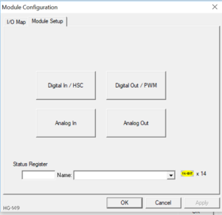
Select Digital In/HSC to open the Digital/HSC Input configuration dialog for a specific controller.
Return to the Top: Digital I/O
Digital Outputs
Solid State Digital Outputs
Solid-state![]() Generally used to activate lamps, low voltage solenoids, relays, and other low voltage and low current devices. digital outputs are generally used to activate lamps, low voltage solenoids
Generally used to activate lamps, low voltage solenoids, relays, and other low voltage and low current devices. digital outputs are generally used to activate lamps, low voltage solenoids![]() Cylindrical coil of wire acting as a magnet when carrying electric current., relays, and other low voltage and low current devices.
Cylindrical coil of wire acting as a magnet when carrying electric current., relays, and other low voltage and low current devices.
Note: The digital outputs used on some controllers are “sourcing![]() In positive logic mode, a positive voltage applied to the input will turn the input. The internal design of this mode is basically a resistor from the input to I/O ground.” outputs. This means the output applies a positive voltage to the output pin when turned ON. When turned off, the output applies approximately zero volts with respect to the I/O ground. Use the Documentation Page to view the datasheet for a specific controller for specifics on a module's I/O.
In positive logic mode, a positive voltage applied to the input will turn the input. The internal design of this mode is basically a resistor from the input to I/O ground.” outputs. This means the output applies a positive voltage to the output pin when turned ON. When turned off, the output applies approximately zero volts with respect to the I/O ground. Use the Documentation Page to view the datasheet for a specific controller for specifics on a module's I/O.
The digital outputs used in the OCS have electronic short circuit protection and current limiting. While these electronic protections work in most applications, some application may require external fusing on these outputs. The digital outputs in the OCS are typically controlled via %Q bits in the register mapping. Some of the outputs are designed for high-speed applications and can be used for PWM or frequency output applications. When the controller is stopped, the operation of each output is configurable. The outputs can hold the state they were in before the controller stopped or they can go to a predetermined state. By default, digital outputs turn off.
Note: The digital outputs feature an output fault bit. %I32 will turn on if any of the outputs experience a short circuit, over-current or the output driver overheats.
Relay Outputs
Relay outputs are designed to switch loads that typically have high voltage or current requirements or require the isolation that relays provide. Relay outputs are not available on all controllers, see the datasheet.
Note: The design of the OCS does not require external coil power for the relays to function.
The relays will activate anytime the OCS is powered. There are several factors that should be considered when using relays:
-
Relay Life – Relays are mechanical devices that have a long but limited life. Typically, switching more current limits the life of relays. Please check the data sheets at the end of this manual for expected relay life.
-
Current / Temperature De-Rating – Products containing relays often have total current limits based on the ambient temperature of the application. Please see the product data sheet for current / temperature de-rating information for relays.
-
Fusing – External fusing is generally required to protect the relays, devices and wiring from shorts or overloads.
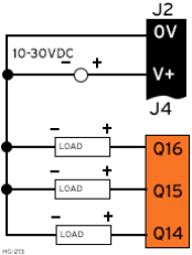
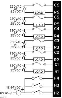
Warning: To protect the module and associated wiring from load faults, use external (5A) fuse(s) as shown. Fuses of lower current or fusing for the entire system need to be in place to assure the maximum current rating of the unit is not exceeded.
Warning: Connecting high voltage to any I/O pin can cause high voltage to appear at other I/O pins.
Below is an example of Relay Fusing:
Protection for Inductive Loads
Inductive loads can cause reverse currents when they shut off that can shorten the life of relay contacts. Some protective measures need to be determined by an engineer. Below you will find recommendations that will work for many applications. If you have additional questions on protection from inductive load, consult an application engineer or Horner Technical Support. Details on devices that may protect outputs can be found in the Spark Quencher Datasheet, MAN0962, which is located on the website.
Output State on Controller Stop
When the controller is stopped, the operation of each output is configurable. The outputs can hold the state they were in before the controller stopped or they can go to a predetermined state. By default, relay outputs turn off.
Return to the Top: Digital I/O
Digital Output Configuration
Home > Hardware Configuration [select Device Type/Model#] > Local I/O Tab > I/O/Config Button > Module Setup > Digital Out/PWM
Select Hardware Configuration from the Home menu and ensure that the correct Device Type and Model# are selected. Then select the Local I/O tab.
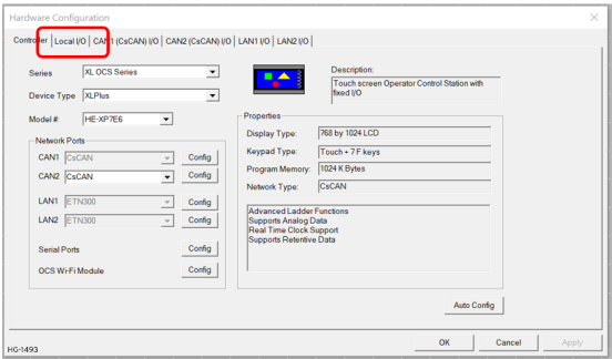
After selecting Local I/O, select the Config button next to the I/O connector.

The Module Configuration screen will appear, select the Module Setup tab. See below.
The Module Setup allows a user to configure four types of I/O.
Note: Not all controllers offer all four types. Refer to the controller's datasheet on the Horner website's Documentation Page for more information regarding specific models.

Select Digital Out/PWM to open the Digital/PWM Output Configuration dialog:
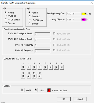
The Q1 and Q2 group boxes allow the user to specify the operation of the multifunction outputs.
PWM State On Controller Stop - Contains items that allow the user to specify how the PWM outputs behave when the controller is stopped. These items can either hold their value or default to some value when the controller is stopped.
Note: The PWM outputs are set to the OFF state at power-up and during program download and remain in that state until the unit is placed in RUN.
Output State On Controller Stop - Contains items to allow the user to specify how the remaining digital outputs behave when the controller is stopped. These items can either hold their value or default to some value when the controller is stopped.
Note: The number of Output States on Controller Stop vary by product.
Stop State
When a controller stops running ladder logic, the state of most output I/O modules can be configured. By default digital outputs turn OFF and analog outputs go to a zero output level. Outputs can be configures to hold the last state the outputs was in when the controller stopped, or it can be configured to go to a predefined state.
Note: When a controller is in DO I/O mode the outputs are still controlled by the values in the controller's registers.
Note: The number of Output State on Controller Stop varies by controller. See the datasheet on the Documentation Page for more details.
Return to the Top: Digital I/O