Analog Inputs
See also: General I/O Configuration
Topic Menu

|
Analog I/O in the OCS |
Analog Input Configuration
The analog inputs on the OCS allow voltage or current measurement from a variety of devices. The voltage or current mode is set though jumpers on the unit and settings in Cscape. Each channel can be separately configured for voltage or current mode. The analog inputs have a digital filter that can be used to filter electrical noise that may be unavoidable in some installations. The downside to digital filtering is the inputs will respond more slowly to sudden changes in the actual input.
Home > Hardware Configuration [select Device Type/Model#] > Local I/O Tab > I/O/Config Button > Module Setup > Analog In
Select Hardware Configuration from the Home menu and ensure that the correct Device Type and Model# are selected. Then select the Local I/O tab.
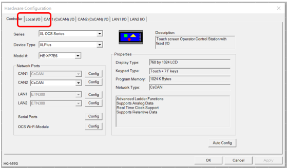
After selecting Local I/O, select the Config button next to the I/O connector.
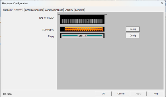
The Module Configuration screen will appear, select the Module Setup tab. See below.
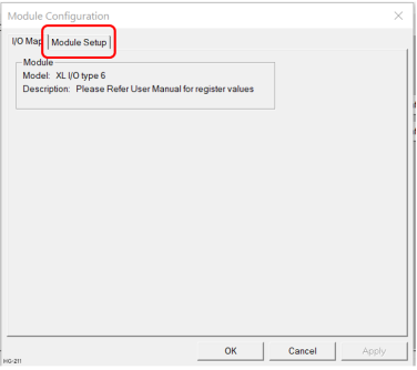
The Module Setup allows a user to configure four types of I/O.
Note: Not all controllers offer all four types. Refer to the controller's datasheet on the Horner website's Documentation Page for more information regarding specific models.
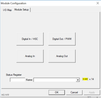
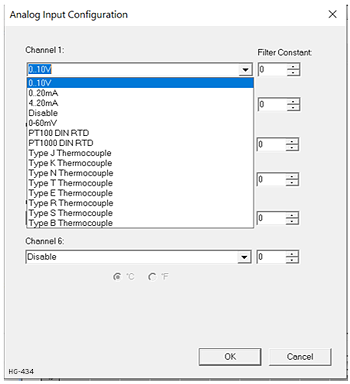
Select Analog In to open the Analog Input Configuration dialog:
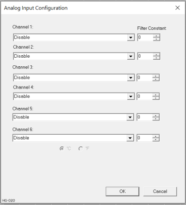
The Channel x drop down windows allow the user to specify the mode for each analog input to operate. The Channel x drop down windows are enabled/disabled according to which model is being configured. All of the models have the following modes available:
-
0..10V
-
0..20mA
-
4..20mA
On the XL series, the Model 5 and Model 6 modules have more channel options.
Return to the Top: Analog Inputs
Universal Analog Inputs Model 5
The universal analog inputs provide a high resolution, very flexible interface for a variety of analog inputs. These inputs include voltage, current, thermocouple![]() A sensor used to measure temperature. Thermocouples consist of two wire legs made from different metals. The wires legs are welded together at one end, creating a junction. This junction is where the temperature is measured. When the junction experiences a change in temperature, a voltage is created. The voltage can then be interpreted using thermocouple reference tables to calculate the temperature., RTD
A sensor used to measure temperature. Thermocouples consist of two wire legs made from different metals. The wires legs are welded together at one end, creating a junction. This junction is where the temperature is measured. When the junction experiences a change in temperature, a voltage is created. The voltage can then be interpreted using thermocouple reference tables to calculate the temperature., RTD![]() RTD - Resistance Temperature Detector - A resistor for which the electrical resistivity is a known function of the temperature., and millivolt. Each channel can be configured separately using jumpers and configuration settings in Cscape. Like the standard analog inputs, these inputs have a digital filter that can be used to filter electrical noise that may be unavoidable in some installations. The downside to digital filtering is the inputs will respond more slowly to sudden changes in the actual input.
RTD - Resistance Temperature Detector - A resistor for which the electrical resistivity is a known function of the temperature., and millivolt. Each channel can be configured separately using jumpers and configuration settings in Cscape. Like the standard analog inputs, these inputs have a digital filter that can be used to filter electrical noise that may be unavoidable in some installations. The downside to digital filtering is the inputs will respond more slowly to sudden changes in the actual input.
|
Analog In for Model 5 |
|---|
|
Channels 1 & 2 |
|
0..10V |
|
0..20mA |
|
4..20mA |
|
100mV |
|
PT100 DIN RTD, 1/20°C |
|
Type J Thermocouple, 1/20°C |
|
Type K Thermocouple, 1/20°C |
|
Type N Thermocouple, 1/20°C |
|
Type T Thermocouple, 1/20°C |
|
Type E Thermocouple, 1/20°C |
|
Type R Thermocouple, 1/20°C |
|
Type S Thermocouple, 1/20°C |
|
Type B Thermocouple, 1/20°C |
|
* The Filter Constant provides filtering to all channels. |
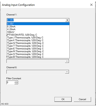
Model 5 Universal Analog Input Configuration
-
Select Analog In to access the Analog Input Configuration menu.
-
Select any of the Analog input types from the drop-downs by clicking the down arrow beneath each corresponding Channel, as seen below:
-
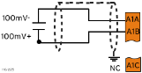
Ensure the proper wiring is used for each of the pins on the Universal Analog Inputs as seen in the image and table below:
|
0-10V Analog In
|
mV In
|
Thermocouple In
|
4-20 mA Analog Out
|
|
20mA Analog In - NOT
|
20mA Analog In -Self-Powered
|
RTD In
|
0-10 V Analog Out
|

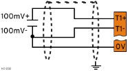
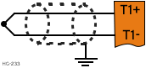
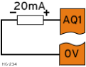
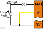
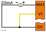
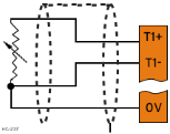
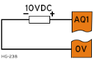
Table for Model 5 Universal Wiring
| J3 Connector for Universal Wiring | |
|---|---|
| T1+ | TC (1+) or RTD (1+) or 100mV (1+) |
| T1- | TC (1-) or RTD (1-) or 100mV (1-) |
| T2+ | TC (2+) or RTD (2+) or 100mV (2+) |
| T2- | TC (2-) or RTD (2-) or 100mV (2-) |
| AQ1 | 10V or 20mA OUT (1) |
| AQ2 | 10V or 20mA OUT (2) |
| 0V | Common |
| MA1 | 0-20mA IN (1) |
| V1 | 0-10V IN (1) |
| 0V | Common |
| MA2 | 0-20mA IN (2) |
| V2 | 0-10V IN (2) |
| 0V | Common |
Return to the Top: Analog Inputs
Universal Analog Inputs Model 6
The Universal Analog Inputs on the Model 6 IO board are unique from other Horner XL-series input/output cards in that they are configurable through the module configuration instead of having to change jumper settings in order to setup the input type.
|
Analog In for Model 6 |
|---|
|
Channels 1-6 |
|
0..10V |
|
0..20mA |
|
4..20mA |
|
Disable |
|
0-60mV |
|
PT100 DIN RTD, 1/10°C |
|
PT1000 DIN RTD, 1/10°C |
|
Type J Thermocouple, 1/10°C |
|
Type K Thermocouple, 1/10°C |
|
Type N Thermocouple, 1/10°C |
|
Type T Thermocouple, 1/10°C |
|
Type E Thermocouple, 1/10°C |
|
Type R Thermocouple, 1/10°C |
|
Type S Thermocouple, 1/10°C |
|
Type B Thermocouple, 1/10°C |
Model 6 Universal Analog Input Type Configuration
-
Select Analog In to access the Analog Input Configuration menu.
-
Select any of the Analog input types from the drop-downs by clicking the down arrow beneath each corresponding Channel, as seen below:
-
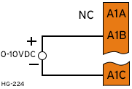
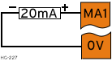
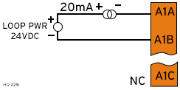
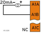
Ensure the proper wiring is used for each of the 3 pins A , B, and C on the Universal Analog Inputs as seen in the reference image below:
0-10V Analog In
mV In
Thermocouple In
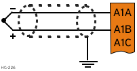
4-20 mA Analog Out
20mA Analog In - Self-Powered
20mA Analog In - Self-Powered
RTD In
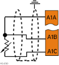
0-10V Analog Out

Note: Depending on the transmitter, isolated loop power may be required.
Return to the Top: Analog Inputs
Scaling Analog Inputs & Examples

|
Analog I/O Scaling in Cscape |

|
Combustion Boiler Control Cscape Example |
To access the Advanced Math Scaling function, select Home > View > Project Toolbox. This will open a side bar, and then select Advanced Math > Scale.
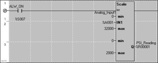
Example 1
The Cscape Scale function, found in the Advanced Math functions, allows for very easy conversion of the raw input value into a meaningful reading. For example, a pressure transducer may be specified as a 4-20mA signal to signify a 0-2000 psi pressure reading. With the analog channel set to the 4..20mA range, the raw analog input value, which is in INT![]() Integer - [Data Type INT] - A 16-bit signed value. Integers are used where the value of the data is expected to be in the range of -32,768 to +32,767. format ranges from 0 to 4mA to 32000 for 20mA. Use the Scale function to obtain an Integer pressure reading using the 0-32000 raw input range and the sensor’s 0-2000psi output range.
Integer - [Data Type INT] - A 16-bit signed value. Integers are used where the value of the data is expected to be in the range of -32,768 to +32,767. format ranges from 0 to 4mA to 32000 for 20mA. Use the Scale function to obtain an Integer pressure reading using the 0-32000 raw input range and the sensor’s 0-2000psi output range.
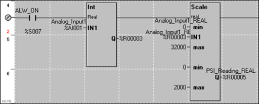
Example 2:
If readings with fractions are required, the raw Integer input value must first be translated in REAL, or Floating Point Format, see note below. . The Cscape INT-to-REAL Conversion function may be used to convert the raw input value from INT to REAL format in an intermediate memory location. The SCALE function, specified as REAL type, may be used to scale the converted raw value into a reading that supports digits beyond the decimal place, i.e. 475.25psi.
Note: Entering Floating Point Values
All floating numbers must adhere to the following format:
These numbers use IEEE 754-1985 format to store numbers in following ranges.
32-bit single-precision floating point (REAL) – -3.40282E+38 to +3.40282E+38
64-bit double-precision floating point (LREAL) – -1.79769E+308 to +1.7976E+308
Floating Point refers to both REAL and LREAL data types.
If an exponent is included, the mantissa (value) portion must also contain a decimal point.
Note: If the entered format is other than x.yyy, the decimal point is moved and the exponent adjusted accordingly:
-
123.456e+3 = 123456 (The actual value can be displayed with six digits and no exponent)
-
143.643E-12 = 1.43643E-10 (Decimal point is moved and exponent adjusted)
A decimal point must be included to reduce any ambiguities. For example, 123e10 should be entered as 123.0e10, or better still 1.23e12 (Cscape will automatically convert to this format).
Neither the mantissa nor the exponent may contain spaces. "123 45e-12" and "4.3256e
-23" will not be interpreted correctly because of the embedded spaces.
Both the mantissa and the exponent may contain a sign, + or -; i.e.: "-1.3245e+12" or "4.243e-8". if the sign is missing then the associated part is assumed to be positive, "1.2345e10".
Return to the Top: Analog Inputs