CANOpen Ladder Elements
See also: Project Toolbox for Advanced Ladder
Topic Menu
Receive Emergency Message from Any Device
CANOpen Elements Overview
NOTE: CANOpen ladder blocks are available only on CANOpen supported models: XLE, XLT, XL6, XL10e, NX and QXBA, ST and AD.
SDO Write Block
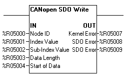
This element is used to change given object dictionary entry or to change the OCS register contents. If node is Master then using this block an object dictionary entry of any slave node in the network can be modified. In case of Slave only own object dictionary entries can be modified.
The element properties window is as shown below:
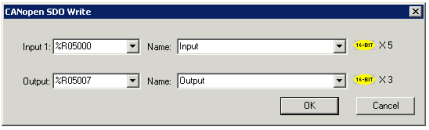
Where:
Input 1 is specified as a Register Type and Offset reference. This register is the first of five (5) registers that contain the information for the SDO write CAN message.
Word 1 Node ID – Node ID of the device (1 to 127) in case of Master only. For accessing the object dictionary / OCS register contents for self node, value 0 needs to be used.
Word 2 Index Value – Any valid 16-bit address to access the CANOpen dictionary supported by the node; for array and records the address is extended by an 8-bit sub-index.
Word 3 Sub-Index value – Any valid 8-bit sub-address to access the sub-objects of arrays and records supported by the node.
Word 4 Data Length - Amount of data to write (Max data length can be 4 bytes)
Word 5 Start of Data - Any valid Register address.
Output is specified as a Register Type and Offset reference. This register is the first of three (3) registers that contain the information of output data.
Word 1 Kernel Error – Gives value of Kernel Error.
Word 2 SDO Error – SDO Error (Higher 16 bits)
Word 3 SDO Error – SDO Error (Lower 16 bits)
The following example Writes Sync ID of 0x85 to device with ID 2.
Input:
%R5000 = 0x02 (Node ID)
%R5001 = 0x1005 (Object Index for Sync ID)
%R5002 = 0x0 (Sub-Index Value)
%R5003 = 0x4 (Data Length)
%R5004 = 0x85 (Start of data)
On enabling input power, SDO Write request will be sent.
If device is in Operational state prior to executing SDO write command, then ladder block output will be:
Output:
%R5007 = 0xFF (Kernel Error)
%R5008 = 0x22 (SDO Error)
%R5009 = 0x800 (SDO Error)
Note: FW 16.30 (XLPrime) and below versions supports working of SDO blocks only till %R2048.
Return to the Top: CANOpen Ladder Elements
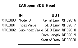
This element reads the given object dictionary entry or the OCS register contents. If node is Master then using this block an object dictionary entry of any slave node in the network can be read. In case of Slave only own object dictionary entries can be read.
The element properties window is as shown below:
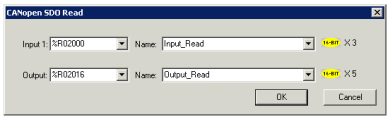
Where:
Input 1 is specified as a Register Type and Offset reference. This register is the first of three (3) registers that contain the information for the SDO read CAN message.
Word 1 Node ID – Node ID of the device (1 to 127) in case of Master only. For accessing the object dictionary / OCS register contents for self node, value 0 needs to be used.
Word 2 Index Value – Any valid 16-bit address to access the CANOpen dictionary supported by the node; for array and records the address is extended by an 8-bit sub-index.
Word 3 Sub-Index value – Any valid 8-bit sub-address to access the sub-objects of arrays and records supported by the node.
Output is specified as a Register Type and Offset reference. This register is the first of five (5) registers that contain the information of output data.
Word 1 Kernel Error – Gives value of Kernel Error.
Word 2 SDO Error – SDO Error (Higher 16 bits)
Word 3 SDO Error – SDO Error (Lower 16 bits)
Word 4 Data Length – Amount of data to read (Max data length can be 4 bytes)
Word 5 Start of Data – Any valid Register address.
For Example:
Read Sync ID from the device with ID 2.
Input:
%R2000 = 0x02 (Node ID)
%R2001 = 0x1005 (Object Index for Sync ID)
%R2002 = 0x0 (Sub Index Value)
On enabling input power, SDO Read request will be sent.
If device is in Operational state prior to executing SDO write command, then ladder block output will be:
Output:
%R2016 = 0x0 (Kernel Error)
%R2017 = 0x0 (SDO Error)
%R2018 = 0x0 (SDO Error)
%R2019 = 0x4 (Data length)
%R2020 = 0x85 (Start of data)
Note: FW 16.30 (XLPrime) and below versions supports working of SDO blocks only till %R2048.
Return to the Top: CANOpen Ladder Elements
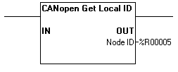
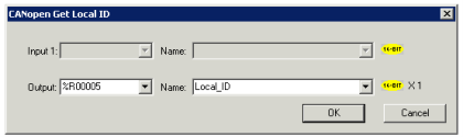
This element reads the local CANOpen node ID.
Enabling the input power to this element gets the Local Node ID in the configured register.
The element properties window is as shown:
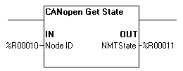
This element reads the local or slave node CANOpen NMT state.
The element properties window is as shown:
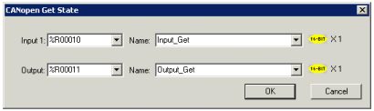
Where:
Input 1 Node ID – Node ID of the device for which NMT state needs to be obtained. For accessing the NMT state of self node, value 0 needs to be used.
Output NMT State – Gives the NMT state of the device.
Following are the possible NMT states and their values in Hex:
| NMT State | Value in Hex |
| Preoperational | 7F |
| Operational | 5 |
| Stop | 4 |
For example:
Get NMT state of Slave Node ID 2.
Input:
%R0010 = 0x02
On enabling input power, NMT state of given node will be stored in the configured register.
Output:
%R0011 = 0x05 (Operational)
Return to the Top: CANOpen Ladder Elements
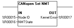
This element sets NMT state of given node in the CANOpen network. This block can only be used if node is configured as Master.
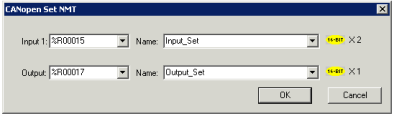
The element properties window is as shown:
Where:
Input 1 is specified as a Register Type and Offset reference. This register is the first of two (2) registers that contain the information of input data.
Word 1 Node ID- Node ID of the device. For setting the NMT state of self node, value 0 needs to be used.
Word 2 NMT State - NMT command of corresponding NMT State.
Following are the NMT commands for corresponding NMT States:
| States | NMT Commands |
| Preoperational | 0x80 |
| Operational | 0x01 |
| Stop | 0x02 |
| Reset Comm | 0x82 |
| Rest Node | 0x81 |
Output Kernel Error - Indicates any kernel error
For example:
Set NMT state of Slave Node ID 2 to Pre-Operational
Input:
%R0015 = 0x02
%R0016 = 0x80 (Command value set Node state to Pre-operational)
On enabling input power, NMT message will be sent from the Master.
Output:
%R0017 = 0x00 (Kernel Error)
Return to the Top: CANOpen Ladder Elements
Receive Emergency Message from a Given Device
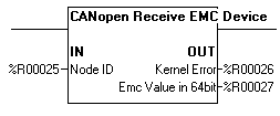
This element is used to receive emergency message from specific device.
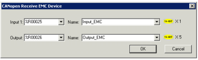
The element properties window is as shown:
Where:
Input 1 1 Node ID- Node ID of the device for which emergency message needs to be received.
Output - is specified as a Register Type and Offset reference. This register is the first of five (5) registers of the output data.
Word 1 Kernel Error - Gives value of Kernel Error
Word 2 EMC Value in 64 Bit - Gives the emergency message/codes.
Word 3 - Lower 8 bit represents Error register and upper 8 Bit Manufacturer specific error field.
Word 4 - Higher 16 bits of Manufacturer specific error.
Word 5 - Lower 16 bits of Manufacturer specific error.
For Example:
Receive Emergency message from the device with Slave ID 2.
Input:
%R0025 = 0x02
Enable input power to the block; the output power will be enabled when Emergency message received from configured node.
Output:
%R0026 = 0x00 - Kernel Status (Kernel Error)
%R0027 = 0x1000 - Emergency Code
%R0028 = 0x0001 - Lower 8 bit Represents Error register and upper 8 Bit Manufacturer specific error field.
%R0029 = 0x0140 - Manufacturer Specific Error (Higher 16 bits)
%R0030 = 0x0000 - Manufacturer Specific Error (Lower 16 bits)
Return to the Top: CANOpen Ladder Elements
Receive Emergency Message from Any Device
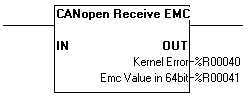
This element is used to receive emergency message from any device in the network.
The element properties window is as shown:
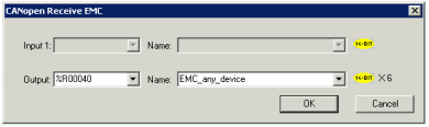
Where:
Output -is specified as a Register Type and Offset reference. This register is the first of Six (6) registers.
Word1 Kernel Error– Gives value of Kernel Error.
Word 2 Node ID – Device Node ID
Word 3 EMC Value in 64 bit – Indicates the emergency message/codes.
Word 4 – Lower 8 bit represents Error register and upper 8 Bit Manufacturer specific error field.
Word 5 – Higher 16 bits of Manufacturer specific error.
Word 6 – Lower 16 bits of Manufacturer specific error.
For Example:
Receive Emergency message for any node.
Enable input power to the block, when Emergency message received from, output power will be enabled.
Output:
%R0040 = 0x00 - Kernel Status (Kernel Error)
%R0041 = 0x02 - Device Node ID
%R0042 = 0x1000 - Emergency Code
%R0043 = 0x0001 - Lower 8 bit Represents Error register and upper 8 Bit Manufacturer specific error field.
%R0044 = 0x0140 - Manufacturer Specific Error (Higher 16 bits)
%R0045 = 0x0000 - Manufacturer Specific Error (Lower 16 bits)
Note: Manufacturer specific error field represents Horner CANOpen Status register contents.
Kernel Error:
0x0 No Kernel Error.
0x1 Other Kernel Errors.
0x21 SDO Engine is Busy.
0x22 Memory Access Error.
0x23 SDO Timeout Error.
0x24 Not Supported.
0x25 Emergency Busy Error.
0x26 Input Data Error.
0xFE Waiting for Response.
0xFF Kernel Not Active
SDO Error:
0x5040002 Invalid Block Size.
0x5040003 Invalid Sequence Count.
0x6010000 Index Not Supported.
0x6010002 Index Read Only.
0x6070012 Data Length is high.
0x6070013 Data Length is Low.
0x8000022 Invalid NMT State.
0x6040041 PDO Mapping Failed.
0x6040042 PDO Length Exceeded.
0x6090011 Sub Index Not Supported.
0x6090030 Value Range Exceeded.
0x6040043 Parameter Incompatible
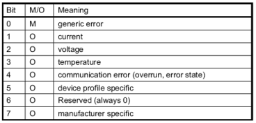
Error Register Bit Details
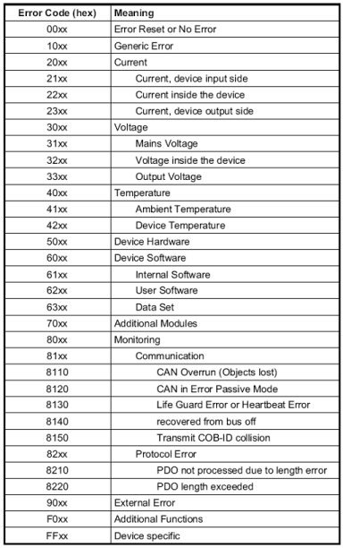
Emergency Codes
Return to the Top: CANOpen Ladder Elements