Bitwise in Advanced Ladder
See also: Bit Set, Bit Clear, Bit Test in Advanced Ladder
See also: Project Toolbox for Advanced Ladder
Topic Menu
Home > View > Project Toolbox > Bitwise Operations
The Bitwise Operations are a group of functions that allow manipulation of data at the bit level. They are operations that are performed on bit patterns rather than values. They are specified to operate on either a WORD![]() Word - [Data Type WORD] - A string of 16 consecutive bits. WORD values are used where the value of the data is not as important as the bit patterns (shifts and rotates). (16 bits) of data or DWORD
Word - [Data Type WORD] - A string of 16 consecutive bits. WORD values are used where the value of the data is not as important as the bit patterns (shifts and rotates). (16 bits) of data or DWORD![]() DWORD - [Data Type DWORD] - A string of 32 consecutive bits. DWORD values are used where the value of the data is not as important as the bit patterns (shifts and rotates). (32 bits) of data.
DWORD - [Data Type DWORD] - A string of 32 consecutive bits. DWORD values are used where the value of the data is not as important as the bit patterns (shifts and rotates). (32 bits) of data.
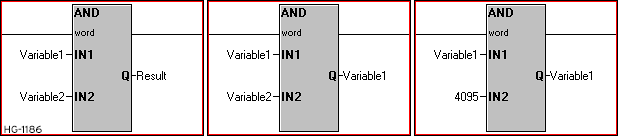
AND 
Also called: AND MASK. This function performs a bitwise AND of two inputs, on each corresponding bit of those WORD or DWORD inputs.
AND Truth Table for two single bits:
|
Bit 1 |
Bit 2 |
Bit1 AND Bit 2 |
|---|---|---|
|
0 |
0 |
0 |
|
0 |
1 |
0 |
|
1 |
0 |
0 |
|
1 |
1 |
1 |
Bit 1 AND Bit 2 must be TRUE for the result to be TRUE.
AND Parameters
-
IN1/IN2: The Input 1/Input 2 parameters can be either variables or static values. These are the two values to execute the function upon.
-
Q: The Output can be specified as its own variable or can overwrite one of the input variables by using the same variable for the output.
-
Type: The AND function may be specified to operate on either WORD or DWORD variables/values. All parameters must be of the same type.
Power Flow
-
The AND function executes immediately and entirely as soon as it receives power from the incoming rung. The Output (Q) is available for any other use immediately.
-
The AND function will execute on every scan that it has received power from the incoming rung.
-
The AND function will always pass power flow to the next function on the rung. There is no way for the function to fail the operation.
-
There is no need for any further functions to exist to the right of the AND function on the rung. The function’s result is considered an output.
|
AND Function Examples |
||
|---|---|---|
|
|
Example 1 |
Example 2 |
|
IN1 |
0000 0000 0000 0111 (UINT 7) |
1010 1010 1010 1010 (UINT 43690) |
|
IN2 |
0000 0000 0000 1010 (UINT 10) |
0000 0000 1111 1111 (UINT 255) |
|
Q (IN1 AND IN2)0 |
0000 0000 0000 0010 (UINT 2) |
0000 0000 1010 1010 (UINT 170) |
In Example 2, note how the upper byte of IN1 has been “masked off”. IN2 acts as the mask. The result is the same as IN1 but only those bits where the mask bits are 1.
Return to the Top: Bitwise in Advanced Ladder
OR 
Also called OR MASK. This function performs a bitwise OR of two inputs, on each corresponding bit of those WORD or DWORD inputs.
OR Truth Table for two single bits:
|
Bit 1 |
Bit 2 |
Bit1 AND Bit 2 |
|---|---|---|
|
0 |
0 |
0 |
|
0 |
1 |
1 |
|
1 |
0 |
1 |
|
1 |
1 |
1 |
If either Bit 1 OR Bit 2 is TRUE, the result is TRUE.
OR Parameters
-
IN1/IN2: The Input 1/Input 2 parameters can be either variables or static values. These are the two values to execute the function upon.
-
Q: The Output can be specified as its own variable or can overwrite one of the input variables by using the same variable for the output.
-
Type: The OR function may be specified to operate on either WORD or DWORD variables/values. All parameters must be of the same type.

Power Flow
-
The OR function executes immediately and entirely as soon as it receives power from the incoming rung. The Output (Q) is available for any other use immediately.
-
The OR function will execute on every scan that it has received power from the incoming rung.
-
The OR function will always pass power flow to the next function on the rung. There is no way for the function to fail the operation.
-
There is no need for any further functions to exist to the right of the OR function on the rung. The function’s result is considered an output.
|
OR Function Examples |
||
|---|---|---|
|
|
Example 1 |
Example 2 |
|
IN1 |
0000 0000 0000 0111 (UINT 7) |
1010 1010 1010 1010 (UINT 43690) |
|
IN2 |
0000 0000 0000 1010 (UINT 10) |
0000 0000 1111 1111 (UINT 255) |
|
Q (IN1 OR IN2)0 |
0000 0000 0000 1111 (UINT 15) |
1010 1010 1111 1111 (UINT 43775) |
In Example 2, note how the upper byte of IN1 has been retained by using a 0 for the mask bits. The lower byte has had every bit turned on by using a 1 for the mask bits.
Return to the Top: Bitwise in Advanced Ladder
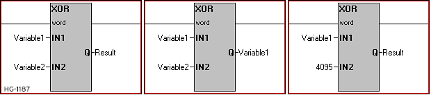
Boolean XOR 
Also called Exclusive OR. This function performs a bitwise XOR (Exclusive OR) of two inputs, on each corresponding bit of those WORD or DWORD inputs.
XOR Truth Table for two single bits:
|
Bit 1 |
Bit 2 |
Bit1 AND Bit 2 |
|---|---|---|
|
0 |
0 |
0 |
|
0 |
1 |
0 |
|
1 |
0 |
0 |
|
1 |
1 |
1 |
If either Bit 1 is TRUE OR Bit 2 is TRUE, but not both, the result is TRUE.
XOR Parameters
-
IN1/IN2: The Input 1/Input 2 parameters can be either variables or static values. These are the two values to execute the function upon.
-
Q: The Output can be specified as its own variable or can overwrite one of the input variables by using the same variable for the output.
-
Type: The XOR function may be specified to operate on either WORD or DWORD variables/values. All parameters must be of the same type.
Power Flow
-
The XOR function executes immediately and entirely as soon as it receives power from the incoming rung. The Output (Q) is available for any other use immediately.
-
The XOR function will execute on every scan that it has received power from the incoming rung.
-
The XOR function will always pass power flow to the next function on the rung. There is no way for the function to fail the operation.
-
There is no need for any further functions to exist to the right of the XOR function on the rung. The function’s result is considered an output.
|
XOR Function Examples |
||
|---|---|---|
|
|
Example 1 |
Example 2 |
|
IN1 |
0000 0000 0000 0111 (UINT 7) |
1010 1010 1010 1010 (UINT 43690) |
|
IN2 |
0000 0000 0000 1010 (UINT 10) |
0000 0000 1111 1111 (UINT 255) |
|
Q (IN1 XOR IN2)& |
0000 0000 0000 1101 (UINT 13)& |
1010 1010 0101 0101 (UINT 43605) |
In Example 2, note how the upper byte of IN1 has been retained in the result by using 0 for the mask bits but the lower byte has been reversed by using 1 for the mask bits.
Return to the Top: Bitwise in Advanced Ladder
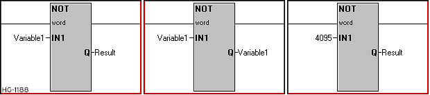
Boolean NOT 
Also called NOT. This function performs a bitwise NOT on each bit of a single WORD or DWORD input, effectively reversing the state of every bit.
NOT Truth Table for a single bit:
|
Bit 1 |
0 |
1 |
|
NOT Bit 1& |
1 |
0 |
If the bit is FALSE, it becomes TRUE. If the bit is TRUE, it becomes FALSE.
NOT Parameters
-
IN1: The Input 1 parameter can be either a variable or static value. This is the value to execute the function upon.
-
Q: The Output can be specified as its own variable or can overwrite the input variable by using the same variable for the output.
-
Type: The NOT function may be specified to operate on either WORD or DWORD variables/values. All parameters must be of the same type.
Power Flow
-
The NOT function executes immediately and entirely as soon as it receives power from the incoming rung. The Output (Q) is available for any other use immediately.
-
The NOT function will execute on every scan that it has received power from the incoming rung.
-
The NOT function will always pass power flow to the next function on the rung. There is no way for the function to fail the operation.
-
There is no need for any further functions to exist to the right of the NOT function on the rung. The function’s result is considered an output.
|
NOT Function Examples |
||
|---|---|---|
|
|
Example 1 |
Example 2 |
|
IN1 |
0000 0000 0000 0111 (UINT 7) |
1010 1010 1010 1010 (UINT 43690) |
|
Q (NOT IN1)& |
1111 1111 1111 1000 (UINT 65528)& |
0101 0101 0101 0101 (UINT 21845) |
In the examples, note how every bit has been reversed.
Return to the Top: Bitwise in Advanced Ladder
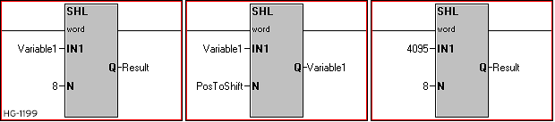
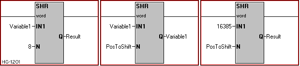
Shift Bits Left & Shift Bits Right 

Also called SHL-Shift Bits Left or SHR - Shift Bits Right. These functions perform a bitwise shift to the left or to the right by the specified number of bits on a single WORD or DWORD input. The last bit shifted out is indicated by power flow. Bits shifted into vacated places are always 0.
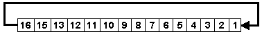
Left and Right Orientation
Shift Left, direction is from Least Significant to Most Significant

Shift Right, direction is from Most Significant to Least Significant

Shift Left/Right Parameters
-
IN1: The Input 1 parameter can be either a variable or static value. This is the value to execute the function upon.
-
N: The number of bit positions to shift by. Can be either a variable or static value.
-
Q: The Output can be specified as its own variable or can overwrite the input variable by using the same variable for the output.
-
Type: The Shift functions may be specified to operate on either WORD or DWORD variables/values. All parameters must be of the same type.
Power Flow
-
The Shift functions execute immediately and entirely as soon as they receive power from the incoming rung. The Output (Q) is available for any other use immediately.
-
The Shift functions will execute on every scan that they have received power from the incoming rung.
-
The Shift functions will pass power flow to the next function on the rung depending on the state of the last bit to be shifted out. If the last bit out was a 0, power is not passed. If the last bit out was a 1, power is passed to the next function.
-
There is no need for any further functions to exist to the right of the Shift functions on the rung. The function’s result is considered an output. Be aware of the power flow description above if functions are placed afterward.
|
Shift Left Function Examples |
|||
|---|---|---|---|
|
|
Example 1 |
Example 2 |
Example 3 |
|
IN1 |
0000 0000 0000 0111 |
1010 1010 1010 1010 |
1111 1111 0000 0000 |
|
N |
8 |
8 |
4 |
|
Q |
0000 0111 0000 0000& |
1010 1010 0000 0000 |
1111 0000 0000 0000 |
|
Power Flow |
FALSE |
FALSE |
TRUE |
|
Shift Right Function Examples |
|||
|---|---|---|---|
|
|
Example 1 |
Example 2 |
Example 3 |
|
IN1 |
0000 0000 0000 0111 |
1010 1010 1010 1010 |
1111 1111 0000 0000 |
|
N |
8 |
8 |
4 |
|
Q |
0000 0000 0000 0000& |
0000 0000 1010 1010& |
0000 1111 1111 0000 |
|
Power Flow |
FALSE |
TRUE |
FALSE |
If the N parameter is 16 or larger for WORD Shifts or 32 or larger with DWORD shifts, the entire output is zeroed.
Return to the Top: Bitwise in Advanced Ladder
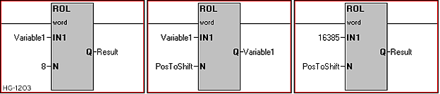
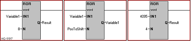
Rotate Bits Left & Rotate Bits Right in Advanced Ladder


Also called ROL - Rotate Bits Left or ROR - Rotate Bits Right. These functions perform a bitwise rotate to the left or to the right by the specified number of bits on a single WORD or DWORD input.
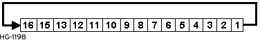
Left and Right Orientation
Rotate Left, direction is from Least Significant to Most Significant
Rotate Right, direction is from Most Significant to Least Significant
Rotate Left/Right Parameters
-
IN1: The Input 1 parameter can be either a variable or static value. This is the value to execute the function upon.
-
N: The number of bit positions to rotate by. Can be either a variable or static value.
-
Q: The Output can be specified as its own variable or can overwrite the input variable by using the same variable for the output.
-
Type: The Rotate functions may be specified to operate on either WORD or DWORD variables/values. All parameters must be of the same type.
Power Flow
-
The Rotate functions execute immediately and entirely as soon as they receive power from the incoming rung. The Output (Q) is available for any other use immediately.
-
The Rotate functions will execute on every scan that they have received power from the incoming rung.
-
The Rotate functions will always pass power flow to the next function on the rung.
-
There is no need for any further functions to exist to the right of the Rotate functions on the rung. The function’s result is considered an output.
| Rotate Left Function Examples | |||
|---|---|---|---|
| Example 1 | Example 2 | Example 3 | |
| IN1 | 0000 0000 0000 0111 | 1100 0000 0000 0000 | 1111 1111 0000 0000 |
| N | 8 | 2 | 4 |
| Q | 0000 0111 1110 0000& | 0000 0000 0000 0011& | 1111 0000 0000 1111 |
| Power Flow | TRUE | TRUE | TRUE |
| Rotate Right Function Examples | |||
|---|---|---|---|
| Example 1 | Example 2 | Example 3 | |
| IN1 | 0000 0000 0000 0111 | 1010 1010 1010 1010 | 1111 1111 0000 0000 |
| N | 8 | 8 | 4 |
| Q | 0000 0000 0000 0000& | 0000 0000 1010 1010& | 0000 1111 1111 0000 |
| Power Flow | FALSE | FALSE | FALSE |
For Example 1 of both Rotate Left and Rotate Right, note how the outcome is the same. The Upper and Lower bytes are “byte swapped”. If the N parameter is 16 or larger for WORD Rotates or 32 or larger with DWORD Rotates, the output will be the same as the input.
Return to the Top: Bitwise in Advanced Ladder