Alarm Handling in Advanced Ladder 
See also: Project Toolbox for Advanced Ladder
Topic Menu

|
Alarm Handling |
Alarm Handling Overview
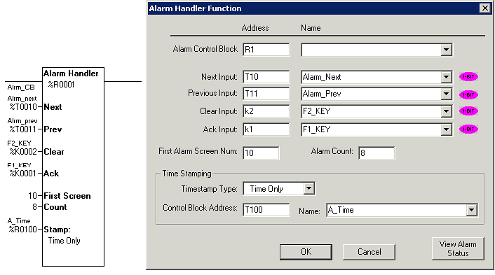
The alarm handling function block provides automatic display screen selection based on the current state of one or more alarms. The alarm handling function block also acts as an alarm database controller in that each alarm may be time stamped, counted, acknowledged, and cleared. Complete versatility is provided by allowing the user to create a custom alarm screen for each defined alarm. This typically includes a user-defined message and information from the alarm database such as alarm status, alarm count and time/date stamp information. Once a defined alarm occurs, its associated alarm screen is automatically displayed. Once the displayed alarm is acknowledged and cleared (usually the user intervention provided though the OCS keypad), the previous display screen (or other pending alarms) is displayed.
Note: Only one Alarm Handling function block can be executed per scan. Executing more than one Alarm function can cause erratic screen handling. If more than one block is desired in the same ladder program, make sure it is disabled by using JUMP or CALL instructions to force the execution of a single block.
The Alarm Handler function block operation is similar to the Graphical Alarm System included in this package. Alarm Handler ladder element is intended to be used in text based controllers and Graphical Alarm System with Graphics controllers.
Alarm Status Registers - Alarm Control Block
Each alarm require one 16-bit status register. The registers for multiple alarms are defined in a contiguous block called the Alarm Control Block. One bit is written to this register to indicate that the alarm is active. The register also contains sections that indicates the acknowledge and pending status and contains a count for the alarm. By placing the alarm status registers in a section of retentive memory (%R, %M...) the alarm states will be retained through a power cycle.
The following table shows how the bits in the alarm status word (control block) are allocated:
|
Bits |
16-12 |
11 |
10 |
9 |
8-1 |
|
Definition |
Undefined* |
Acknowledge |
Pending |
Active |
Alarm Count |
Alarm Count - This is a BYTE counter that counts how many times an alarm occurs. The count only increments when the pending bit goes from low to high. To count another alarm event the alarm must be acknowledged, cleared and reactivated. When the count reaches a maximum of 255 it no longer changes until reset. This count can be reset by writing directly to this portion of the register using one of the BYTE instructions.
Active - This bit is set by the user's ladder program to indicate an alarm condition has occurred. For example, if the alarm is to indicate an over-temperature condition, have the ladder logic perform a compare, then set this bit if the compare indicates the temperature is greater than a setpoint.
Pending - This bit is set by the function block when the Active bit is high and is reset through the functions block's Clear operation. If the Active bit is high when Pending is reset, a new alarm will be recognized and Pending will be set immediately.
Acknowledge - This bit is set by the function block after a pending alarm has been acknowledged.
Special Status Bits
-
Bit 16 of the first status word turns ON when any alarm is pending (but may be acknowledged).
-
Bit 15 of the first status word turn ON when any alarm is unacknowledged.
User Interface Settings
When alarms are being displayed (one or more alarms pending and power flow enabled to the block) there are four inputs that control the user interface to the function block. These inputs have no affect if there are no pending alarms or if there is no power flow to the alarm handler function block.
Next - When this input transitions from low to high, the next (higher alarm number) pending alarm is shown on the display. If the highest alarm is being displayed, the alarm number is not incremented further.
Prev - When this input transitions from low to high, the previous (lower alarm number) pending alarm is shown on the display. If the lowest alarm is being displayed, the alarm number is not decremented further.
Clear - When this input transitions from low to high, the currently displayed alarm is cleared if it has already been acknowledged. If it has not been acknowledged this input has no affect. Once the alarm is cleared, the function block immediately searches for the next active alarm screen to display by searching for the next (higher) alarm status register with a Pending bit set. If a pending alarm is found, that associated screen will be immediately displayed. Otherwise, the %SR2 register will be set to zero and the current user screen (%SR1) will be displayed. If an alarm is cleared that is still active, the pending bit will be set and if no other alarm is active will continue to be displayed.
Ack - When this input transitions from low to high, the currently displayed alarm is marked as acknowledged. This will set the acknowledge bit in the status register and allow the alarm to be cleared.
First Alarm Screen Num (First Screen) - defines the first in a block of screens that will be used to display alarm information. Alarm 1 will cause the screen defined by First Screen to be displayed, Alarm 2 will cause the first screen plus one to be displayed.
Alarm Count (Count) - sets the total number of alarms defined. This number also sets how many registers are used for status registers, how many text screens are reserved for alarm display, and how many registers are reserved for time stamping (if enabled).
Time Stamp Registers
Time stamping can be set to one of three modes:
- None - No time stamping is performed and no additional register space is required.
- Time Only - The time is recorded when each alarm's pending bit becomes active. Each alarm requires three (3) registers starting at the block defined by the time stamping control block. The time is recorded in the same format as the real-time-clock is stored in the system registers.
- Time and Date - The time and date is recorded when each alarm's pending bit becomes active. Each alarm requires six (6) registers starting at the block defined by the time stamping control block. The time and date is recorded in the same format as the real-time-clock is stored in the system registers.
Power Flow
This function block only displays the pending alarms when power flow to the function block is ON. Alarm screens are displayed by modifying %SR2 to force a screen based on the pending alarms and the NEXT and PREV inputs.
When power flow into the function block is OFF, the block continues to monitor the alarm active bits to record alarm conditions including incrementing the alarm count, but does not display the alarms.
Viewing the Alarm Handler Status from Cscape
From the alarm function block properties press the View Alarm Status button to view the following dialog:
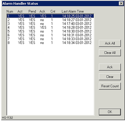
This dialog allows viewing real-time information for the alarms for the currently connect target controller. Alarms can be acknowledged, cleared, or the alarm counter can be cleared from this dialog.
Return to the Top: Alarm Handling in Advanced Ladder